EP1927723A1 - Stator stage of an axial compressor in a flow engine with transverse fins to increase the action - Google Patents
Stator stage of an axial compressor in a flow engine with transverse fins to increase the action Download PDFInfo
- Publication number
- EP1927723A1 EP1927723A1 EP07022949A EP07022949A EP1927723A1 EP 1927723 A1 EP1927723 A1 EP 1927723A1 EP 07022949 A EP07022949 A EP 07022949A EP 07022949 A EP07022949 A EP 07022949A EP 1927723 A1 EP1927723 A1 EP 1927723A1
- Authority
- EP
- European Patent Office
- Prior art keywords
- transverse
- stator
- blade
- wall
- blades
- Prior art date
- Legal status (The legal status is an assumption and is not a legal conclusion. Google has not performed a legal analysis and makes no representation as to the accuracy of the status listed.)
- Granted
Links
- 241000446313 Lamella Species 0.000 claims description 35
- 230000007423 decrease Effects 0.000 claims description 6
- 238000013461 design Methods 0.000 claims description 5
- 230000007103 stamina Effects 0.000 claims 1
- 238000000926 separation method Methods 0.000 description 28
- 239000012530 fluid Substances 0.000 description 7
- 230000009467 reduction Effects 0.000 description 4
- 238000011835 investigation Methods 0.000 description 3
- 230000008901 benefit Effects 0.000 description 2
- 238000007664 blowing Methods 0.000 description 2
- 230000008859 change Effects 0.000 description 2
- 230000008602 contraction Effects 0.000 description 2
- 230000003111 delayed effect Effects 0.000 description 2
- 238000002474 experimental method Methods 0.000 description 2
- 241001295925 Gegenes Species 0.000 description 1
- 230000006978 adaptation Effects 0.000 description 1
- 230000002411 adverse Effects 0.000 description 1
- 230000015572 biosynthetic process Effects 0.000 description 1
- 230000000740 bleeding effect Effects 0.000 description 1
- 239000013256 coordination polymer Substances 0.000 description 1
- 230000003247 decreasing effect Effects 0.000 description 1
- 230000001419 dependent effect Effects 0.000 description 1
- 230000000694 effects Effects 0.000 description 1
- 230000010354 integration Effects 0.000 description 1
- 238000005259 measurement Methods 0.000 description 1
- 230000007246 mechanism Effects 0.000 description 1
- 238000000034 method Methods 0.000 description 1
- 230000002093 peripheral effect Effects 0.000 description 1
- 230000008092 positive effect Effects 0.000 description 1
- 230000001902 propagating effect Effects 0.000 description 1
- 239000007787 solid Substances 0.000 description 1
- 230000003068 static effect Effects 0.000 description 1
- 230000001629 suppression Effects 0.000 description 1
- 238000012360 testing method Methods 0.000 description 1
- 230000032258 transport Effects 0.000 description 1
- 238000011144 upstream manufacturing Methods 0.000 description 1
- XLYOFNOQVPJJNP-UHFFFAOYSA-N water Substances O XLYOFNOQVPJJNP-UHFFFAOYSA-N 0.000 description 1
Images


Classifications
-
- F—MECHANICAL ENGINEERING; LIGHTING; HEATING; WEAPONS; BLASTING
- F04—POSITIVE - DISPLACEMENT MACHINES FOR LIQUIDS; PUMPS FOR LIQUIDS OR ELASTIC FLUIDS
- F04D—NON-POSITIVE-DISPLACEMENT PUMPS
- F04D29/00—Details, component parts, or accessories
- F04D29/40—Casings; Connections of working fluid
- F04D29/52—Casings; Connections of working fluid for axial pumps
- F04D29/54—Fluid-guiding means, e.g. diffusers
- F04D29/541—Specially adapted for elastic fluid pumps
- F04D29/542—Bladed diffusers
-
- F—MECHANICAL ENGINEERING; LIGHTING; HEATING; WEAPONS; BLASTING
- F01—MACHINES OR ENGINES IN GENERAL; ENGINE PLANTS IN GENERAL; STEAM ENGINES
- F01D—NON-POSITIVE DISPLACEMENT MACHINES OR ENGINES, e.g. STEAM TURBINES
- F01D5/00—Blades; Blade-carrying members; Heating, heat-insulating, cooling or antivibration means on the blades or the members
- F01D5/12—Blades
- F01D5/14—Form or construction
- F01D5/141—Shape, i.e. outer, aerodynamic form
- F01D5/145—Means for influencing boundary layers or secondary circulations
-
- F—MECHANICAL ENGINEERING; LIGHTING; HEATING; WEAPONS; BLASTING
- F04—POSITIVE - DISPLACEMENT MACHINES FOR LIQUIDS; PUMPS FOR LIQUIDS OR ELASTIC FLUIDS
- F04D—NON-POSITIVE-DISPLACEMENT PUMPS
- F04D29/00—Details, component parts, or accessories
- F04D29/40—Casings; Connections of working fluid
- F04D29/52—Casings; Connections of working fluid for axial pumps
- F04D29/54—Fluid-guiding means, e.g. diffusers
- F04D29/541—Specially adapted for elastic fluid pumps
- F04D29/542—Bladed diffusers
- F04D29/544—Blade shapes
-
- F—MECHANICAL ENGINEERING; LIGHTING; HEATING; WEAPONS; BLASTING
- F04—POSITIVE - DISPLACEMENT MACHINES FOR LIQUIDS; PUMPS FOR LIQUIDS OR ELASTIC FLUIDS
- F04D—NON-POSITIVE-DISPLACEMENT PUMPS
- F04D29/00—Details, component parts, or accessories
- F04D29/66—Combating cavitation, whirls, noise, vibration or the like; Balancing
- F04D29/68—Combating cavitation, whirls, noise, vibration or the like; Balancing by influencing boundary layers
- F04D29/681—Combating cavitation, whirls, noise, vibration or the like; Balancing by influencing boundary layers especially adapted for elastic fluid pumps
-
- F—MECHANICAL ENGINEERING; LIGHTING; HEATING; WEAPONS; BLASTING
- F05—INDEXING SCHEMES RELATING TO ENGINES OR PUMPS IN VARIOUS SUBCLASSES OF CLASSES F01-F04
- F05D—INDEXING SCHEME FOR ASPECTS RELATING TO NON-POSITIVE-DISPLACEMENT MACHINES OR ENGINES, GAS-TURBINES OR JET-PROPULSION PLANTS
- F05D2250/00—Geometry
- F05D2250/10—Two-dimensional
- F05D2250/13—Two-dimensional trapezoidal
Definitions
- the invention relates to a stator stage of an axial compressor of an axial flow machine, which comprises at least one stator blade, which comprises a suction side and a pressure side.
- Rotor and stator stages are used alternately in axial flow machines in an axial compressor.
- an axial compressor as used for example in a gas turbine, an attempt is made to obtain the highest possible pressure build-up in each stage.
- a profile design of stator blades is made. The profile is set so that a forming flow on the stator blades remains in a working area corresponding to a design.
- the blades are bounded laterally by walls, an outer wall forming a housing, and an inner wall forming a hub. On these walls, relatively thick boundary layers are formed, especially in the middle and high-pressure compressor area. From measurements taken by J.
- a turbomachine with intermediate blades known as flow guide There is provided for reducing secondary flow losses of fluid flow through a bladed flow channel of a turbomachine to arrange at least one intermediate blade between two full blades on at least one flow-limiting side wall.
- a depth of the intermediate blade is less than a depth of the full blades that extend from one boundary wall to an opposite boundary wall.
- a profile thickness is much thinner than that of a full bucket.
- a suction-side profile of the intermediate blade is preferably contoured in the same way as the suction-side profile of the full blade.
- the blade channel is subdivided locally into subchannels and a leading edge (blade nose) of the intermediate blades is set back (in the flow direction) relative to the leading edges (blade lugs) of the full blades.
- the trailing edge of the intermediate blade is preferably offset from the rear edges of the full blades, that is, offset from a main flow direction.
- a turbomachine with a turnaround passage formed between two adjacent blades and boundary surfaces is known.
- For reducing a secondary flow of a boundary layer fluid at least one projecting from the boundary surface of the flow channel fence is provided.
- a depth with which the fence projects into the passage resembles, for example, a thickness of the local boundary layer.
- the projecting depth of the fence increases with a distance along the chord at a rate sufficient to limit the steady increase in boundary layer fluid along the fence.
- the invention is therefore based on the technical object to provide a compressor stage for an axial compressor of a turbomachine, in which the losses, in particular due to flow separation on the walls, are reduced, that is, an increase in efficiency is achieved.
- a stator stage of an axial compressor of a turbomachine comprising at least one stator blade, which in turn comprises a suction side and a pressure side, spaced from at least one wall, to which the stator blade adjacent to the suction side the stator vane extend a plurality of cross blades in a flow volume, wherein Quedamellen chord lengths of the plurality of cross blades with a distance from the suction side of the stator blade decrease.
- the flow volume is that volume of the stator stage through which a fluid flows during operation.
- Such transverse blades which are arranged on a wall spaced from the suction side of a stator blade between two adjacent stator blades, are capable of influencing a secondary flow forming therefrom from a pressure side of a stator blade arranged adjacent to the suction side of the at least one stator blade Extent of detachment is reduced and thereby a Resistance or loss due to the secondary flow along the at least one wall is reduced. Furthermore, it is achieved by the plurality of transverse lamellae that a secondary flow promoted corner separation at the at least one wall adjacent, in the main flow direction rear corner of the stator blade suction side is reduced, which also leads to a reduction in the efficiency losses.
- the transverse lamellae comprise a first side and an opposite second side whose surface normal to a surface normal of the at least one wall is an angle between 70 ° and 110 °, more preferably between 85 ° and 95 ° and most preferably of 90 °. This means that the transverse lamellae each extend preferably in the radial direction into the flow volume from the wall. This ensures that the secondary flow which forms parallel to the wall surface is best prevented from propagating.
- a particularly small additional flow resistance due to the transverse lamellae is obtained when the first side of the transverse lamellae has a surface curvature which corresponds to the surface curvature of the suction side of the at least one stator blade.
- the second side of the transverse lamellae has the same surface curvature as the first side.
- the cross blades in this embodiment a parallel aligned first and second side, each having a surface curvature corresponding to that of the stator blade, which has the stator blade in the corresponding area adjacent to the at least one wall.
- the transverse blades are preferably oriented so that the surface of the suction side of the at least one stator blade can be brought into registry with the first side of the transverse blades by rotations about a central axis of the compressor stage.
- transverse lamella or the first side of each transverse lamella can thus be regarded as a surface section of the stator blade, which is arranged so as to be twisted along the wall about an azimuthal angle about the central axis of the axial compressor.
- the transverse lamellae have a front edge facing the main flow and an opposite rear edge, an outer edge adjoining the at least one wall and an inner edge projecting into the flow volume and lying opposite the outer edge, wherein a maximum transverse lamella chord length , measured from the leading edge to the trailing edge, is greater than a maximum cross-blade depth measured from the outer edge to the inner edge.
- the transverse lamella chord length of the suction side closest to the plurality of transverse lamellae is between 30% to 70%, more preferably between 40% and 60%, and most preferably 50%, of a stator chord.
- the cross lamella with the maximum quedamella chord length has a transverse lamella chord length of 50% of a stator chord length in order to optimally influence the secondary flow and adds no "unnecessary" flow resistance beyond the positive effect to the compressor stage ,
- a contour of the transverse lamellae is in each case preferably designed such that a front and inner contour of the transverse lamella approximates and / or corresponds to a streamline course of the main flow, spaced from the wall. This ensures that the cross-blade is flowed around by the main flow as low as possible and provides no additional flow resistance or the lowest possible additional flow resistance.
- the front contour faces the main flow direction.
- the inner contour protrudes into the flow volume, i. into a passage between the stator wings, into it.
- a good approximation is obtained with a transverse lamella in which a chamfered edge is formed between the front edge and the inner edge.
- An embodiment which has proven to be particularly advantageous is one in which one of the plurality of transverse lamellae has an equidistant spacing from the suction side of the stator blade and the several transverse lamellae are mutually spaced apart. This means that the transverse lamellae are equidistant from each other and from the stator blade in the azimuthal direction. The area along the wall is thus subdivided into several zones, thereby eliminating pressure equalization along the wall between the various zones. As advantageous, a cross-plate number between 2 and 10 has been found.
- Other embodiments may provide a non-equidistant arrangement of the transverse blades.
- a distance between 3% and 7%, more preferably between 4% and 6% and most preferably 5% of a profile length of the suction side of the stator blade has been found.
- the transverse lamella depth of the plurality of transverse lamellae has the same maximum transverse lamella depth.
- the transverse lamella depth of the plurality of transverse lamellae decreases with a distance from the suction side of the stator blade.
- the configuration of the stator stage is particularly advantageous when extending from one of the at least one wall opposite wall to which the at least one stator blade also adjacent, one or preferably also a plurality of additional transverse lamellae.
- the at least one wall can represent both an outer wall and a hub.
- transverse lamellae are arranged on both the hub-forming wall and the outer wall.
- the arrangement of the transverse lamellae preferably takes place such that in each case the rear edge of the plurality of transverse lamellae and / or the additional transverse lamellae terminate with a corresponding rear edge of the stator blade in the axial direction of the turbomachine.
- the secondary flow is formed between the stator blades. This means that in the axial direction behind the stator blades no cross blades arranged transversely to the propagation direction of the secondary flow have to be provided.
- the transverse lamellae are arranged such that their rear edge does not terminate with the edge of the profile of the stator blade but "end" in the main flow direction in front of the stator blade trailing edge, then at least a part of the secondary flow can form such that corner removal is undesirably assisted.
- the plurality of transverse fins are arranged within a volume in which a secondary flow caused by wall detachment from the pressure side of an adjacently arranged further stator blade to the suction side of the at least one stator blade forms into the main flow in an operation corresponding to a design of the turbomachine the at least one transverse lamella and / or the further transverse lamellae are aligned transversely to the secondary flow.
- the orientation of the Slats transverse to this Sekundarströmun.9. Is the cause of the designation of the slats as cross blades. This is transverse not only in the sense of 90 ° to understand.
- FIG. 3 schematically a section of a stator stage of an axial compressor according to the prior art is shown.
- the stator stage comprises at least one stator blade 1. Adjacent to the at least one stator blade 1, a further stator blade 1 'is arranged. The at least one stator blade 1 and the adjacent stator blade 1 'each adjoin a wall 2 forming an outer wall.
- a flow direction of a main flow 4 is indicated by double arrows.
- a thickness of a wall boundary layer 4c grows in the region of the stator blade 1 or adjacent stator blade 1 '. This is due to the fact that the main flow 4 is delayed by a profiling of the stator blade 1 or adjacent stator blade 1 '.
- a main axis of the turbomachine is oriented parallel to the display plane. Profiles of three stator blades 1, 1 ', 1 "can be seen: The main direction of flow is from bottom left to top right This flow direction, which deviates from an axial direction of the turbomachine, is caused by a rotor stage located upstream of the stator stage visualized flow lines 4a is in Fig. 1 to recognize that it comes in a passage 6 between the stator blades 1 to a flow separation.
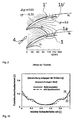
- FIG. 2 is one with Fig. 1 corresponding schematic representation of a wall pressure distribution of a stator stage according to the prior art shown.
- Fig. 1 corresponding schematic representation of a wall pressure distribution of a stator stage according to the prior art shown.
- Lines of constant static pressure cp less than 0 are entered by means of dashed lines and the line constants of positive pressure by solid thin lines.
- the line shown in bold and denoted by SL represents a detachment line.
- the inflow direction of the main flow 4 is indicated by an arrow. It can be seen that the detachment line SL runs obliquely to the main flow direction.
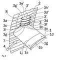
- Fig. 4 schematically a section of a stator stage of an axial compressor is shown, in which spaced from the suction side 1a of the stator blade 1, a transverse blade 3 and further transverse blades 3 'are arranged, which extend from the wall 2 in a flow volume 7.
- the stator blade 1 has a profile length 1j and a chord length 1g.
- the cross-blade 3 preferably has a clearance from the suction side 1a which is preferably between 3% and 7%, more preferably between 4% and 6% and most preferably 5% of the profile length 1j of the suction side 1a of the stator blade 1. The same distance, the cross blades 3, 3 'of each other.
- a surface of the suction side 1a of the stator blade 1 can be brought to cover the first side 1a by a virtual rotation along the azimuth direction 8 about the central axis of the turbomachine.
- the fins 3 and further fins 3 'further have a main flow 4 facing front edge 3c, 3c' and an opposite edge 3d, 3d 'on. Between the front edge 3c, 3c 'and the rear edge 3d, 3d', a maximum transverse lamella chord length 3g or 3g 'can be determined.
- the transverse lamella 3 and the further transverse lamellae 3 'furthermore have one of the outer wall facing Outer edge 3e or 3e 'and a projecting into the flow volume 7 inner edge 3f and 3f. Between the outer edge 3e and the inner edge 3f, a transverse lamella depth 3h or 3h 'can be determined in each case.
- the lamellae are designed such that a maximum transverse chord length 3g is greater than a maximum cross lobe depth 3h.
- cross blades 3, 3 ' are formed so that the front edge 3c and the inner edge 3f are interconnected by a tapered edge 3i. This means that a "front inner corner" of the transverse blades 3, 3 'is bevelled. This causes an adaptation to a flow line course of the main flow 4 adjacent to the transverse blades 3, 3 '.
- Fig. 6 is a section of a schematic cross-sectional drawing through a stator stage shown with the embodiment according to Fig. 4 corresponds.
- a stator 1 is arranged between a outer wall 2a and an opposite wall 2b, which forms the hub.
- the illustrated embodiment is intended to indicate a real stator stage only schematically.
- the transverse louver depth 3h, 3h ' is shown greatly enlarged in relation to a distance of the wall 2a from the opposite wall 2b.
- a preferred embodiment of a stator stage is shown schematically.
- the related to Fig. 4 described features and advantages apply essentially also for the embodiment according to Fig. 5 , In this embodiment, however, decreases both a Queriamellen chord length 3g, 3g 'and a transverse lamella depth 3h, 3h' with a distance from the suction side 1a of the stator blade of the individual transverse blades 3, 3 'from. This leads to an optimal Reduction of unwanted losses.
- Both in the embodiment according to Fig. 4 as well as the embodiment according to Fig. 5 closes the rear edge 3d, 3d 'of the cross blades in each case with a rear edge 1d of the stator blade in the axial direction.
- FIG. 5 illustrated embodiment of the stator stage represents a preferred embodiment, it will be apparent to those skilled in the art that embodiments are also conceivable in which the louver depths 3h, 3h 'of the plurality of transverse blades 3, 3' are identical.
- a separation along a separation line 15 is shown, which arises in a flow 14 with a strong pressure gradient. It is believed that the pressure of the outside flow dp dx 16 imposes itself on the pressure of detachment. In the separation region, a secondary flow 14b is created, which is opposite to the flow 14.
- Fig. 10 are introduced in the Abl Harbor which transverse fins 13, which divide the pressure area of the secondary flow into several areas of equal pressure. An expansion of the secondary flow area on the wall 12 is thus reduced and the edge losses are thereby minimized. Between the cross blades 13 there is a formation of an altered secondary flow 14e, which is conducive to an effect of the transverse blades.
- the integrate loss coefficient results from the integration of the local loss coefficient over the blade pitch and the blade height of the compressor grid.
- the blade pitch indicates the distance of the stator blades.
- the stator height indicates a radial span of the stator blade, i. a distance from the hub to the outer wall. It is thus integrated azimuthally and radially.
- a local total pressure loss coefficient results from a difference of the average total pressure of the inflow (indicated by a bar above the variable) and the local total pressure in the wake of the compressor grating, which is normalized with the mean dynamic pressure of the inflow.
- FIG. 10 shows a change in the integrated over the division of the total pressure coefficient In a Verdlchter stator passage (dashed data curve) compared with a reference configuration (solid line of the data curve).
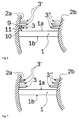
- Figures 11a and 11b are schematic sectional views each represented by a schematic passage of a compressor stator stage transversely to the main propagation direction at the level of a trailing edge of a stator blade, viewed in the direction opposite to the main flow direction, wherein a number of cross blades is different. Shown are schematic compressor stator stage configurations. Shown is a passage of a compressed stator grid, similar to those of 6 and 7 , The illustration is simplified in that the boundary wall 2a and the opposite boundary wall 2b are assumed to be straight.
- the section through the stator stage is shown at the trailing edge transverse to the axial direction, ie, the main flow direction of the stator stage, with an upper edge 24 and a lower edge 25 indicating half a passage height above the stator blade and below the stator blade, respectively, and not actually existing To represent components of the stator.
- the viewing direction is opposite to the main flow direction.
- the trailing edge 1d of the stator blade is located in a center of the considered passage. Above the suction side are located at equidistant intervals a plurality of cross blades 3, 3 '.
- Fig. 11a There are eight cross blades in a passage, three of which have a smaller distance from the pressure side 1b than from the suction side 1a of the stator blade.
- Fig. 11b a view of a stator step passage is shown, which comprises only six transverse blades 3.
- This embodiment is opposite to the Fig. 11a in that the number of transverse lamellae and the wall areas over which the transverse lamellae 3 extend along the wall 2a or the opposite wall 2b approximately coincide with the areas in which a secondary flow running transversely to the main flow direction along the walls 2a, 2b in FIG Operation of the stator can be formed.
- An extension of these areas, in which the disturbing secondary flow is formed, is indicated schematically by a contour 23.
- a transverse lamella depth 3h which indicates how far the individual transverse lamellae project from the side wall 2a or opposite side wall 2b into the flow volume 7, is also important.
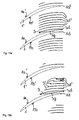
- Fig. 12a and 12b are schematic sectional views again each by a schematic passage of a compressor stator stage transverse to the main flow direction at the level of a trailing edge 1d of a Stator5schaufel similar to those after Fig. 11a and 11b shown. While in both views 12a and 12b a number of the plurality of transverse blades 3, 3 'is optimally selected, the transverse blades protrude in the Fig. 12a all equally far into the flow volume 7 inside. In Fig. 12b On the other hand, the transverse louver depths 3h, 3h ', 3h "of the individual transverse louvers 3, 3', 3" are different.
- a transverse lamella depth 3h, 3h ', 3h decreases with a distance of the transverse lamella 3, 3', 3" from the suction side 1a of the stator blade 1ab. This means that the transverse lamella 3, 3 ', 3 ", which is farthest from the suction side 1a of the stator blade 1, projects the least far into the flow volume 7.
- Such a gradation of the transverse lamella depths 3h, 3h', 3h” forms on best a depth of the secondary flow region 23 measured against the side wall 2a and the opposite side wall 2b from.
- transverse blades 3, 3 ' which are arranged on the side wall 2a and have an identical distance as a corresponding transverse blade 3 ", which is arranged on the opposite side wall 2b, from the suction side 1a of the stator blade, can have a different transverse blade depth 3h, 3h'. 3h "of the corresponding transverse lamella 3.”
- an optimal number of transverse lamellae on the side wall may deviate from that on the opposite side wall.
- Fig. 13a and 13b In each case, a schematic sectional view along a main flow direction or an axial direction of the turbomachine of sections of a schematic compressor stator stage is shown. While at the stator stage, which in Fig. 13a is shown, the individual transverse blades 3, 3 'all have an identical Querlamellensehenentre 3g, takes in Fig. 13b , which represents a preferred embodiment, a Querlamellensehenin 3g with a distance of the transverse blades 3, 3 'from the suction side 1a of the stator blade 1ab.
- the Querlamellensahnannostin 3g are thus optimally adapted to the influenced secondary flow area 23 along the side wall 2.
- a transverse lamellar depth is preferably chosen in this optimal embodiment, as in Fig. 12b is shown. This means that a transverse lamellar depth decreases with a distance from the suction side 1a of the stator blade 1.
- the transverse lamellae and further transverse lamellae have a simple geometric contour.
- the contour is preferably conformed to a streamline shape that forms in the mainstream spaced from the wall.
- This means that the contour of the cross blades is chosen so that they fill the area where the secondary flow forms along the wall as well as possible.
- an optimal suppression of the secondary flow is achieved and at the same time an additional resistance, which is inevitably linked to the cross blades, kept as low as possible.
- the leading edges and the inner edges, including the bevelled edges may form a common continuous contour.
- a (maximum) cross-blade chord length in such a case is a maximum dimension measured along the axial direction of the compressor stage.
- a (maximum) cross-plate depth is correspondingly a maximum distance, measured perpendicular to the adjacent side wall.
- transverse blades and their arrangement are given only by way of example.
- they may have a curvature other than the curvature of the suction side of the stator vanes and be oriented differently along the wall, as long as they are oriented transversely to the secondary flow forming on the wall in the passage between the stator vanes.
Abstract
Description
Die Erfindung betrifft eine Stator-Stufe eines Axialverdichters einer axialen Strömungsmaschine, die mindestens eine Statorschaufel umfasst, die eine Saugseite und eine Druckseite umfasst.The invention relates to a stator stage of an axial compressor of an axial flow machine, which comprises at least one stator blade, which comprises a suction side and a pressure side.
In axialen Strömungsmaschinen werden alternierend Rotor- und Stator-Stufen in einem Axialverdichter verwendet. In einem Axialverdichter, wie er beispielsweise in einer Gasturbine verwendet wird, wird versucht, in jeder Stufe einen möglichst hohen Druckaufbau zu erhalten. Angepasst an diesen Zweck wird eine Profilauslegung von Statorschaufeln vorgenommen. Das Profil wird so festgelegt, dass eine sich ausbildende Strömung auf den Statorschaufeln in einem einer Auslegung entsprechenden Arbeitsbereich anliegend bleibt. Die Schaufeln werden jedoch seitlich durch Wände, eine ein Gehäuse bildende Außenwand und eine eine Nabe bildende Innenwand begrenzt. Auf diesen Wänden bilden sich relativ dicke Grenzschichten aus, besonders im Mittel- und Hochdruckverdichterbereich. Aus Messungen, die von
Eine Möglichkeit, eine Ablösung weitestgehend zu vermeiden besteht darin, eine Kontraktion der Seitenwände vorzusehen, wie es von J. Hübner an dem o. a. Ort vorgeschlagen ist. Eine solche Kontraktion der Seitenwände führt jedoch dazu, dass ein Teil des erwünschten Druckaufbaus verloren geht.One way to avoid a replacement as much as possible is to provide a contraction of the side walls, as proposed by J. Hübner in the above location. However, such contraction of the sidewalls results in losing some of the desired pressure build-up.
Durch eine Entlastung des wandnahen Schaufelbereichs, z.B. durch eine Verwindung, eine Profiländerung und/oder eine Krümmung der Schaufel, kann eine Wandablösung ebenfalls vermieden oder reduziert werden. Ein solches Vorgehen hat jedoch hinsichtlich des Druckaufbaus ebenfalls nachteilige Folgen und/oder ändert ein Strömungsverhalten außerhalb eines optimalen Arbeitspunktes des Verdichters nachteilig.By relieving the wall-near blade area, e.g. By a twist, a profile change and / or a curvature of the blade, a wall detachment can also be avoided or reduced. However, such a procedure also has disadvantageous consequences with respect to the pressure build-up and / or adversely affects a flow behavior outside an optimum operating point of the compressor.
Bei
Eine weitergehende Übersicht über den Stand der Technik hinsichtlich der Auslegung von Axialverdichtern kann man bei
Aus der Offenlegungsschrift
Aus der Offenlegungsschrift
Aus der
Aus der
Insgesamt ist festzustellen, dass in Axialverdichtern ca. 60 % der Verluste durch Strömungsablösungen an den Wänden von Gehäuse und Nabe verursacht werden. Der starke Druckanstieg in einer Verdichterstufe und die dort üblichen Grenzschichtdicken an diesen Seitenwänden führen zwangsläufig an diesen Stellen zu Strömungsablösungen.Overall, it should be noted that in axial compressors about 60% of the losses caused by flow separation on the walls of the housing and hub. The strong increase in pressure in a compressor stage and the boundary layer thicknesses on these side walls customary there inevitably lead to flow separation at these points.
Der Erfindung liegt somit die technische Aufgabe zugrunde, eine Verdichterstufe für einen Axialverdichter einer Strömungsmaschine zu schaffen, bei der die Verluste, insbesondere aufgrund von Strömungsablösungen an den Wänden, reduziert sind, d.h., eine Wirkungsgradsteigerung erreicht wird.The invention is therefore based on the technical object to provide a compressor stage for an axial compressor of a turbomachine, in which the losses, in particular due to flow separation on the walls, are reduced, that is, an increase in efficiency is achieved.
Die Aufgabe wird erfindungsgemäß durch eine Stator-Stufe eines Axialverdichters einer Strömungsmaschine mit den Merkmalen des Patentanspruchs 1 gelöst. Vorteilhafte Ausführungsformen der Erfindung ergeben sich aus den Unteransprüchen.The object is achieved by a stator stage of an axial compressor of a turbomachine with the features of
Zur Erreichung einer Wirkungsgradsteigerung ist vorgesehen, dass sich bei einer Stator-Stufe eines Axialverdichters einer Strömungsmaschine, die mindestens eine Statorschaufel umfasst, welche wiederum eine Saugseite und eine Druckseite umfasst, sich von mindestens einer Wand, an die die Statorschaufel angrenzt, beabstandet zu der Saugseite der Statorschaufel mehrere Querlamellen in ein Strömungsvolumen erstrecken, wobei Quedamellen-Sehnenlängen der mehreren Querlamellen mit einem Abstand von der Saugseite der Statorschaufel abnehmen. Dies bedeutet, dass die der Saugseite der Statorschaufel am nächsten liegende Querlamelle eine größte Querlamellen-Sehnenlänge aufweist und die am weitesten von der Saugseite der Statorschaufel entfernte Querlamelle die kürzeste Querlamellen-Sehnenlänge aufweist. Das Strömungsvolumen ist jenes Volumen der Stator-Stufe, durch das ein Fluid im Betrieb strömt. Solche Querlamellen, die beabstandet zu der Saugseite einer Statorschaufel zwischen zwei benachbarten Statorschaufeln an einer Wand angeordnet sind, sind in der Lage, eine sich dort ausbildende Sekundärströmung von einer Druckseite einer benachbart angeordneten Statorschaufel zu der Saugseite der mindestens einen Statorschaufel so zu beeinflussen, dass eine Ausdehnung der Ablösung verringert wird und hierdurch ein Widerstand bzw. Verlust aufgrund der Sekundarströmung entlang der mindestens einen Wand verringert wird. Ferner wird durch die mehreren Querlamellen erreicht, dass eine durch die Sekundarströmung geförderte Eckenablösung an der an die mindestens eine Wand angrenzenden, in Hauptströmungsrichtung hinteren Ecke der Statorschaufel-Saugseite verringert wird, was ebenfalls zu einer Senkung der Wirkungsgradverluste führt.To achieve an increase in efficiency, it is provided that at a stator stage of an axial compressor of a turbomachine comprising at least one stator blade, which in turn comprises a suction side and a pressure side, spaced from at least one wall, to which the stator blade adjacent to the suction side the stator vane extend a plurality of cross blades in a flow volume, wherein Quedamellen chord lengths of the plurality of cross blades with a distance from the suction side of the stator blade decrease. This means that the transverse lamella closest to the suction side of the stator blade has a largest transverse lamella chord length and the farthest lamella farthest from the suction side of the stator blade has the shortest transverse lamella chord length. The flow volume is that volume of the stator stage through which a fluid flows during operation. Such transverse blades, which are arranged on a wall spaced from the suction side of a stator blade between two adjacent stator blades, are capable of influencing a secondary flow forming therefrom from a pressure side of a stator blade arranged adjacent to the suction side of the at least one stator blade Extent of detachment is reduced and thereby a Resistance or loss due to the secondary flow along the at least one wall is reduced. Furthermore, it is achieved by the plurality of transverse lamellae that a secondary flow promoted corner separation at the at least one wall adjacent, in the main flow direction rear corner of the stator blade suction side is reduced, which also leads to a reduction in the efficiency losses.
Durch ein Vorsehen der Querlamellen 3, 3' können wesentlich höhere Druckanstiege entlang der Wand "ertragen werden", ohne dass eine nachteilige Ablösung der Strömung auftritt. Dies bedeutet, dass bei vorgegebenem Druckaufbau eine wesentlich verkürzte Strecke hierfür ausreicht, ohne dass größere Verluste auftreten. Hierdurch wird es möglich, kompaktere Statorverdichterstufen zu erstellen. Mit den Querlamellen an der Wand wird somit die Ablösung auf den Seitenwänden und ebenso auf der Saugseite der Schaufeln des Verdichtergitters, insbesondere somit eine Eckenablösung, vermindert.By providing the
Bei einer bevorzugten Ausführungsform der Erfindung ist vorgesehen, dass die Querlamellen eine erste Seite und eine gegenüberliegende zweite Seite umfassen, deren Oberflächennormalen zu einer Oberflächennormale der mindestens einen Wand einen Winkel zwischen 70° und 110°, bevorzugter zwischen 85° und 95° und am bevorzugtesten von 90° bilden. Dies bedeutet, dass sich die Querlamellen von der Wand jeweils vorzugsweise in radialer Richtung in das Strömungsvolumen erstrecken. Hierdurch wird gewährleistet, dass die sich parallel zur Wandoberfläche ausbildende Sekundarströmung bestmöglich in ihrer Ausbreitung gehindert wird.In a preferred embodiment of the invention, it is provided that the transverse lamellae comprise a first side and an opposite second side whose surface normal to a surface normal of the at least one wall is an angle between 70 ° and 110 °, more preferably between 85 ° and 95 ° and most preferably of 90 °. This means that the transverse lamellae each extend preferably in the radial direction into the flow volume from the wall. This ensures that the secondary flow which forms parallel to the wall surface is best prevented from propagating.
Einen besonders geringen zusätzlichen Strömungswiderstand aufgrund der Querlamellen erhält man, wenn die erste Seite der Querlamellen eine Oberflächenkrümmung aufweist, die der Oberflächenkrümmung der Saugseite der mindestens einen Statorschaufel entspricht.A particularly small additional flow resistance due to the transverse lamellae is obtained when the first side of the transverse lamellae has a surface curvature which corresponds to the surface curvature of the suction side of the at least one stator blade.
Als ebenso vorteilhaft hat es sich herausgestellt vorzusehen, dass die zweite Seite der Querlamellen eine gleiche Oberflächenkrümmung wie die erste Seite aufweist. Dies bedeutet, dass die Querlamellen bei dieser Ausführungsform eine parallel zueinander ausgerichtete erste und zweite Seite aufweisen, die jeweils eine Oberflächenkrümmung aufweisen, die der der Statorschaufel entspricht, den die Statorschaufel in dem entsprechenden Bereich angrenzend an die mindestens eine Wand aufweist. Die Querlamellen sind bevorzugt so ausgerichtet, dass die Oberfläche der Saugseite der mindestens einen Statorschaufel durch Rotationen um eine zentrale Achse der Verdichterstufe mit der ersten Seite der Querlamellen zur Deckung gebracht werden kann. Die Querlamelle bzw. die erste Seite jeder Querlamelle kann somit als ein Oberflächenausschnitt der Statorschaufel angesehen werden, die entlang der Wand um einen Azimutalwinkel um die zentrale Achse des Axialverdichters verdreht angeordnet ist.It is also advantageous to provide that the second side of the transverse lamellae has the same surface curvature as the first side. This means that the cross blades in this embodiment, a parallel aligned first and second side, each having a surface curvature corresponding to that of the stator blade, which has the stator blade in the corresponding area adjacent to the at least one wall. The transverse blades are preferably oriented so that the surface of the suction side of the at least one stator blade can be brought into registry with the first side of the transverse blades by rotations about a central axis of the compressor stage. The transverse lamella or the first side of each transverse lamella can thus be regarded as a surface section of the stator blade, which is arranged so as to be twisted along the wall about an azimuthal angle about the central axis of the axial compressor.
Bei einer bevorzugten Ausführungsform der Erfindung weisen die Querlamellen eine der Anströmung einer Hauptströmung zugewandte vordere Kante und eine gegenüberliegende hintere Kante, eine an die mindestens eine Wand angrenzende Außenkante sowie eine in das Strömungsvolumen hineinragende, der Außenkante gegenüberliegende Innenkante auf, wobei eine maximale Querlamellen-Sehnenlänge, gemessen von der vorderen Kante zu der hinteren Kante, größer als eine maximale Querlamellentiefe, gemessen von der Außenkante zu der Innenkante, ist. Diese Ausgestaltung bietet den Vorteil, dass die Querlamellen ungefähr an eine Ausdehnung des Sekundärströmungsgebiets angepasst sind. Hierdurch kann eine effektive Beeinflussung der Sekundärströmung durchgeführt werden.In a preferred embodiment of the invention, the transverse lamellae have a front edge facing the main flow and an opposite rear edge, an outer edge adjoining the at least one wall and an inner edge projecting into the flow volume and lying opposite the outer edge, wherein a maximum transverse lamella chord length , measured from the leading edge to the trailing edge, is greater than a maximum cross-blade depth measured from the outer edge to the inner edge. This embodiment offers the advantage that the transverse lamellae are approximately adapted to an extent of the secondary flow area. As a result, an effective influencing of the secondary flow can be carried out.
Da sich die Sekundärströmung entlang der mindestens einen Wand nicht über die gesamte Profillänge des Statorflügelprofils ausbildet, ist bei einer bevorzugten Ausführungsform vorgesehen, dass die Querlamellen-Sehnenlänge der der Saugseite am dichtesten benachbarten der mehreren Querlamellen zwischen 30 % bis 70 %, bevorzugter zwischen 40 % und 60 % und am bevorzugtesten 50 % einer Statorprofilsehnenlänge beträgt. In der Regel reicht es aus, wenn die Querlamelle mit der maximalen Quedamellen-Sehnenlänge eine Querlamellen-Sehnenlänge von 50 % einer Statorprofilsehnenlänge aufweist, um die Sekundärströmung optimal zu beeinflussen und fügt keinen "unnötigen", über die positive Wirkung hinausgehenden Strömungswiderstand zu der Verdichterstufe hinzu.Since the secondary flow along the at least one wall does not form over the entire profile length of the stator vane profile, it is provided in a preferred embodiment that the transverse lamella chord length of the suction side closest to the plurality of transverse lamellae is between 30% to 70%, more preferably between 40% and 60%, and most preferably 50%, of a stator chord. As a rule, it suffices if the cross lamella with the maximum quedamella chord length has a transverse lamella chord length of 50% of a stator chord length in order to optimally influence the secondary flow and adds no "unnecessary" flow resistance beyond the positive effect to the compressor stage ,
Eine Kontur der Querlamellen ist jeweils vorzugsweise so ausgebildet, dass eine vordere und innere Kontur der Querlamelle einem Stromlinienverlauf der Hauptströmung, beabstandet zu der Wand, angenähert ist und/oder ihr entspricht. Hierdurch wird erreicht, dass die Querlamelle von der Hauptströmung möglichst günstig umströmt wird und keinen zusätzlichen Strömungswiderstand oder einen möglichst geringen zusätzlichen Strömungswiderstand liefert. Die vordere Kontur ist der Hauptströmungsrichtung zugewandt. Die innere Kontur ragt in das Strömungsvolumen, d.h. in eine Passage zwischen den Statorflügeln, hinein.A contour of the transverse lamellae is in each case preferably designed such that a front and inner contour of the transverse lamella approximates and / or corresponds to a streamline course of the main flow, spaced from the wall. This ensures that the cross-blade is flowed around by the main flow as low as possible and provides no additional flow resistance or the lowest possible additional flow resistance. The front contour faces the main flow direction. The inner contour protrudes into the flow volume, i. into a passage between the stator wings, into it.
Eine gute Annäherung erhält man bei einer Querlamelle, bei der zwischen der vorderen Kante und der Innenkante eine abgeschrägte Kante ausgebildet ist.A good approximation is obtained with a transverse lamella in which a chamfered edge is formed between the front edge and the inner edge.
Als besonders vorteilhaft hat sich eine Ausführungsform herausgestellt, bei der eine der mehreren Querlamellen von der Saugseite der Statorschaufel und die mehreren Querlamellen voneinander jeweils einen äquidistanten Abstand aufweisen. Dies bedeutet, dass die Querlamellen zueinander und von der Statorschaufel in azimutaler Richtung äquidistant beabstandet sind. Das Gebiet entlang der Wand wird somit in mehrere Zonen unterteilt, hierdurch wird ein Druckausgleich entlang der Wand zwischen den verschiedenen Zonen unterbunden. Als vorteilhaft hat sich eine Querlamellenzahl zwischen 2 und 10 herausgestellt.An embodiment which has proven to be particularly advantageous is one in which one of the plurality of transverse lamellae has an equidistant spacing from the suction side of the stator blade and the several transverse lamellae are mutually spaced apart. This means that the transverse lamellae are equidistant from each other and from the stator blade in the azimuthal direction. The area along the wall is thus subdivided into several zones, thereby eliminating pressure equalization along the wall between the various zones. As advantageous, a cross-plate number between 2 and 10 has been found.
Andere Ausführungsformen können eine nicht äquidistante Anordnung der Querlamellen vorsehen.Other embodiments may provide a non-equidistant arrangement of the transverse blades.
Als optimaler äquidistanter Abstand hat sich ein Abstand zwischen 3 % und 7 %, bevorzugter zwischen 4 % und 6 % und am bevorzugtesten von 5 % einer Profillänge der Saugseite der Statorschaufel herausgestellt.As optimum equidistant spacing, a distance between 3% and 7%, more preferably between 4% and 6% and most preferably 5% of a profile length of the suction side of the stator blade has been found.
Bei einer Ausführungsform der Erfindung ist vorgesehen, dass die Querlamelientiefe der mehreren Querlamellen eine gleiche maximale Querlamellentiefe aufweist.In one embodiment of the invention, it is provided that the transverse lamella depth of the plurality of transverse lamellae has the same maximum transverse lamella depth.
Bei einer anderen bevorzugten Ausführungsform der Erfindung ist vorgesehen, dass die Querlamellentiefe der mehreren Querlamellen mit einem Abstand von der Saugseite der Statorschaufel abnimmt.In another preferred embodiment of the invention it is provided that the transverse lamella depth of the plurality of transverse lamellae decreases with a distance from the suction side of the stator blade.
Die Ausgestaltung der Stator-Stufe ist besonders vorteilhaft, wenn sich zusätzlich aus einer der mindestens einen Wand gegenüberliegenden Wand, an die die mindestens eine Statorschaufel ebenfalls angrenzt, eine oder vorzugsweise ebenfalls mehrere zusätzliche Querlamellen erstrecken. Dies bedeutet, dass die mindestens eine Wand sowohl eine Außenwand als auch eine Nabe darstellen kann. Optimalerweise sind jedoch sowohl an der die Nabe bildenden Wand als auch der Außenwand Querlamellen angeordnet.The configuration of the stator stage is particularly advantageous when extending from one of the at least one wall opposite wall to which the at least one stator blade also adjacent, one or preferably also a plurality of additional transverse lamellae. This means that the at least one wall can represent both an outer wall and a hub. Optimally, however, transverse lamellae are arranged on both the hub-forming wall and the outer wall.
Die Anordnung der Querlamellen erfolgt vorzugsweise so, dass jeweils die hintere Kante der mehreren Querlamellen und/oder der zusätzlichen Querlamellen mit einer entsprechenden hinteren Kante der Statorschaufel in axialer Richtung der Strömungsmaschine abschließen. Die Sekundärströmung bildet sich zwischen den Statorschaufeln aus. Dies bedeutet, dass in axialer Richtung hinter den Statorschaufeln keine durch quer zur Ausbreitungsrichtung der Sekundärströmung angeordnete Querlamellen vorgesehen sein müssen. Werden hingegen die Querlamellen so angeordnet, dass ihre hintere Kante nicht mit der Kante des Profils der Statorschaufel abschließt, sondern in Hauptströmungsrichtung vor der Statorschaufelhinterkante "enden", so kann sich zumindest ein Teil der Sekundarströmung so ausbilden, dass eine Eckenablösung unerwünschterweise unterstützt wird.The arrangement of the transverse lamellae preferably takes place such that in each case the rear edge of the plurality of transverse lamellae and / or the additional transverse lamellae terminate with a corresponding rear edge of the stator blade in the axial direction of the turbomachine. The secondary flow is formed between the stator blades. This means that in the axial direction behind the stator blades no cross blades arranged transversely to the propagation direction of the secondary flow have to be provided. If, on the other hand, the transverse lamellae are arranged such that their rear edge does not terminate with the edge of the profile of the stator blade but "end" in the main flow direction in front of the stator blade trailing edge, then at least a part of the secondary flow can form such that corner removal is undesirably assisted.
Besonders bevorzugt werden die mehreren Querlamellen innerhalb eines Volumens angeordnet, in dem sich eine von der Druckseite einer benachbart angeordneten weiteren Statorschaufel zu der Saugseite der mindestens einen Statorschaufel gerichtete, durch Wandablösung verursachte Sekundarströmung zu der Hauptströmung in einem einer Auslegung der Strömungsmaschine entsprechenden Betrieb ausbildet, wobei die mindestens eine Querlamelle und/oder die weiteren Querlamellen quer zu der Sekundarströmung ausgerichtet sind. Die Ausrichtung der Lamellen quer zu dieser Sekundarströmun.9. Ist ursächlich für die Bezeichnung der Lamellen als Querlamellen. Hierbei ist quer nicht nur im Sinne von 90° zu verstehen.Particularly preferably, the plurality of transverse fins are arranged within a volume in which a secondary flow caused by wall detachment from the pressure side of an adjacently arranged further stator blade to the suction side of the at least one stator blade forms into the main flow in an operation corresponding to a design of the turbomachine the at least one transverse lamella and / or the further transverse lamellae are aligned transversely to the secondary flow. The orientation of the Slats transverse to this Sekundarströmun.9. Is the cause of the designation of the slats as cross blades. This is transverse not only in the sense of 90 ° to understand.
Die Erfindung wird nachfolgend anhand bevorzugter Ausführungsbeispiele unter Bezugnahme auf eine Zeichnung näher erläutert. Hierbei zeigen:
- Fig. 1
- eine Ansicht experimentell sichtbar gemachter Strömungslinien entlang einer Seitenwand einer Stator-Stufe eines Axialverdichters nach dem Stand der Technik,
- Fig. 2
- eine Darstellung einer Druckverteilung, die mit der in
Fig. 1 dargestellten Stator-Stufe korrespondiert nach dem Stand der Technik, - Fig. 3
- eine schematische Darstellung eines Ausschnitts einer Stator-Stufe nach dem Stand der Technik,
- Fig. 4
- eine schematische Darstellung einer AusfOhrungsform einer Stator-Stufe mit Querlamellen, die die gleiche Querlamellen-Sehnenlänge aufweisen,
- Fig. 5
- eine schematische Darstellung eines Ausschnitts einer Stator-Stufe eines Axialverdichters mit Querlamellen, die eine unterschiedliche Querlamellen-Sehnenlänge und eine unterschiedliche Querlamellentiefe aufweisen,
- Fig. 6
- einen schematischen Ausschnitt eines Schnitts durch eine mit der Ausführungsform nach
Fig. 4 korrespondierenden Stator-Stufe, - Fig. 7
- einen Ausschnitt einer Schnittzeichnung durch eine schematische Stator-Stufe einer Ausführungsform nach
Fig. 5 , - Fig. 8, Fig. 9
- schematische Darstellungen einer druckgetriebenen Ablösung an einer ebenen Wand ohne Querlamellen und mit Querlamellen,
- Fig. 10
- eine grafische Darstellung des Totaldruckverlustbeiwerts, aufgetragen gegen eine relative Schaufelhöhe für eine axiale Statorverdichterstufe mit und ohne Querlamellen.
- Fig. 11a, 11b
- schematische Schnittansichten jeweils durch eine schematische Passage einer Verdichter-Statorstufe quer zur Hauptströmungsrichtung einer Hinterkante einer Statorschaufel, betrachtet entgegen der Hauptströmungsrichtung, wobei eine Anzahl der Querlamellen unterschiedlich ist,
- Fig. 12a, 12b
- schematische Schnittansichten jeweils durch eine schematische Passage einer Verdichter-Statorstufe quer zur Hauptströmungsrichtung auf Höhe einer Hinterkante einer Statorschaufel mit einer optimal angepassten Querlamellenanzahl, die eine nicht abgestufte Querlamellentiefe (a) und eine mit einem Abstand vor der Saugseite der Statorschaufel abnehmenden Querlamellentiefe (b) aufweisen, und
- Fig. 13a, 13b
- schematische Schnittansichten entlang einer Hauptströmungsrichtung von Ausschnitten schematischer Verdichter-Statorstufen.
- Fig. 1
- a view of experimentally visualized flow lines along a side wall of a stator stage of an axial compressor according to the prior art,
- Fig. 2
- a representation of a pressure distribution with the in
Fig. 1 Stator stage shown corresponds to the prior art, - Fig. 3
- 1 is a schematic representation of a section of a stator stage according to the prior art,
- Fig. 4
- 1 is a schematic representation of an embodiment of a stator stage with transverse blades, which have the same cross-blade chord length,
- Fig. 5
- 1 is a schematic representation of a section of a stator stage of an axial compressor with transverse blades, which have a different cross-blade chord length and a different cross-blade depth,
- Fig. 6
- a schematic section of a section through one with the embodiment according to
Fig. 4 corresponding stator stage, - Fig. 7
- a section of a sectional drawing through a schematic stator stage of an embodiment according to
Fig. 5 . - Fig. 8, Fig. 9
- schematic representations of a pressure-driven detachment on a flat wall without cross blades and with cross blades,
- Fig. 10
- a plot of the total pressure loss coefficient, plotted against a relative blade height for an axial Statorverdichterstufe with and without cross blades.
- Fig. 11a, 11b
- schematic sectional views in each case by a schematic passage of a compressor stator stage transversely to the main flow direction of a trailing edge of a stator blade, viewed in the direction opposite to the main flow direction, wherein a number of transverse blades are different,
- Fig. 12a, 12b
- schematic sectional views in each case by a schematic passage of a compressor stator stage transversely to the main flow direction at the level of a trailing edge of a stator blade with an optimally adapted Querlamellenanzahl having a non-stepped cross-plate depth (a) and with a distance in front of the suction side of the stator blade decreasing cross-plate depth (b) , and
- Fig. 13a, 13b
- schematic sectional views along a main flow direction of cut-outs of schematic compressor stator stages.
In
Eine Hauptachse der Strömungsmaschine ist parallel zu der Darstellungsebene orientiert. Zu erkennen sind Profile von drei Statorschaufeln 1, 1', 1". Die Hauptanströmungsrichtung erfolgt von links unten nach rechts oben. Diese Strömungsrichtung, die von einer axialen Richtung der Strömungsmaschine abweicht, ist durch eine der Stator-Stufe vorgelagerte Rotorstufe verursacht. Anhand von visualisierten Strömungslinien 4a ist in
In
In
Die Querlamelle 3 und die weiteren Querlamellen 3' weisen jeweils eine erste Seite 3a bzw. 3a' und eine gegenüberliegende Seite 3b bzw. 3b' auf. Diese weisen jeweils eine Krümmung auf, die der Oberflächenkrümmung der Saugseite 1a der Statorschaufel 1 entsprechen. In erster Näherung sind somit die erste Seite 3a und die zweite Seite 3b zueinander parallel, wenn man annimmt, dass eine Lamellenstärke klein gegen einen radialen Durchmesser bzw. eine Statorschaufelhöhe der Axialverdichterstufe ist. Zumindest für die erste Seite 3a gilt vorteilhafterweise, dass eine Oberfläche der Saugseite 1a der Statorschaufel 1 durch eine virtuelle Rotation entlang der Azimutrichtung 8 um die zentrale Achse der Strömungsmaschine zur Deckung mit der ersten Seite 1a gebracht werden kann. Die Lamellen 3 und weiteren Lamellen 3' weisen ferner eine der Hauptströmung 4 zugewandte vordere Kante 3c, 3c' und eine gegenüberliegende Kante 3d, 3d' auf. Zwischen der vorderen Kante 3c, 3c' und der hinteren Kante 3d, 3d' können eine maximale Querlamellen-Sehnenlänge 3g bzw. 3g' ermittelt werden. Die Querlamelle 3 bzw. die weiteren Querlamellen 3' weisen ferner eine der Außenwand zugewandte Außenkante 3e bzw. 3e' und eine in das Strömungsvolumen 7 hineinragende Innenkante 3f bzw. 3f auf. Zwischen der Außenkante 3e und der Innenkante 3f kann jeweils eine Querlamellentiefe 3h bzw. 3h' ermittelt werden. Die Lamellen sind so ausgestaltet, dass eine maximale Querlämellen-Sehnenlänge 3g größer als eine maximale Querlamellentiefe 3h ist. Ferner sind bei der Ausführungsform nach
In
In
Während die in
Durch ein vorsehen der Querlamellen 3, 3' können wesentlich höhere Druckanstiege entlang der Wand "ertragen werden", ohne dass eine nachteilige Ablösung der Strömung auftritt. Dies bedeutet, dass bei vorgegebenem Druckaufbau eine wesentlich verkürzte Strecke hierfür ausreicht, ohne dass größere Verluste auftreten. Hierdurch wird es möglich, kompaktere Statorverdichterstufen zu erstellen. Mit den Querlamellen an der Wand wird somit die Ablösung auf den Seitenwänden und ebenso auf der Saugseite der Schaufeln des Verdichtergitters, insbesondere somit eine Eckenablösung, vermindert.By providing the
Ein Erklärungsansatz, wie die Querlamellen wirken, soll anhand der ![]()
![]()
Bei Versuchen in einem zweidimensionalen Verdichterversuchstand ist ein integraler Totaldruckverlustbeiwert ζ um bis zu 10 % verringert worden. Der Totaldruckverlustbeiwert ζ ist wie folgt definiert: 
-
p r1 : gemittelten Totaldruck der Zuströmung des Verdichtergitters, - pr2 (u,z): lokaler Totaldruck im Nachlauf des Verdichters,
-
q 1 : mittleren dynamischen Druck der Zuströmung des Verdichtergitters.
-
p r1 : averaged total pressure of the inflow of the compressor grille, - p r2 ( u , z ): local total pressure in the wake of the compressor,
-
q 1 : average dynamic pressure of the inflow of the compressor grille.
Der integrate Verlustbeiwert ergibt sich aus der Integration des lokalen Verlustbeiwerts über die Schaufelteilung und die Schaufelhöhe des Verdichtergitters. Die Schaufelteilung gibt den Abstand der Statorschaufeln an. Die Statorhöhe gibt eine radiale Spannweite der Statorschaufel an, d.h. einen Abstand von der Nabe zu der Außenwand. Es wird somit azimutal und radial integriert.The integrate loss coefficient results from the integration of the local loss coefficient over the blade pitch and the blade height of the compressor grid. The blade pitch indicates the distance of the stator blades. The stator height indicates a radial span of the stator blade, i. a distance from the hub to the outer wall. It is thus integrated azimuthally and radially.
Ein lokaler Totaldruckverlustbeiwert ergibt sich aus einer Differenz des gemittelten Totaldruckes der Zuströmung (gekennzeichnet durch einen Strich über der Variablen) und dem lokalen Totaldruck im Nachlauf des Verdichtergitters, der mit dem mittleren dynamischen Druck der Zuströmung normiert wird.A local total pressure loss coefficient results from a difference of the average total pressure of the inflow (indicated by a bar above the variable) and the local total pressure in the wake of the compressor grating, which is normalized with the mean dynamic pressure of the inflow.
In
In
In
Neben der Anzahl der verwendeten Querlamellen 3 in einer Passage ist auch eine Querlamellentiefe 3h, die angibt, wie weit die einzelnen Querlamellen von der Seitenwand 2a bzw. gegenüberliegenden Seitenwand 2b in das Strömungsvolumen 7 hineinragen, von Bedeutung.In addition to the number of
In
In
Die Hinterkanten 3d der Querlamellen und die Hinterkanten 1d der Statorschaufeln 1, 1' liegen alle in einer Ebene. Hierdurch wird, wie oben bereits erwähnt, eine unerwünschte Eckenablösung durch ein Ausbilden einer Querströmung zuverlässig vermieden.The trailing
Bei den hier im Detail beschriebenen Ausführungsformen weisen die Querlamellen und weiteren Querlamellen eine einfache geometrische Kontur auf. Die Kontur ist vorzugsweise einer Stromlinienform angepasst, die sich in der Hauptströmung beabstandet von der Wand ausbildet. Dies bedeutet, dass die Kontur der Querlamellen so gewählt wird, dass sie das Gebiet, in dem sich die Sekundärströmung entlang der Wand ausbildet, möglichst gut ausfüllen. Hierdurch wird eine optimale Unterdrückung der Sekundärströmung erreicht und zugleich ein zusätzlicher Widerstand, der zwangsläufig mit den Querlamellen verknüpft ist, so gering wie möglich gehalten. Die Vorderkanten und die Innenkanten, einschließlich der abgeschrägten Kanten, können eine gemeinsame stetige Kontur bilden.In the embodiments described in detail here, the transverse lamellae and further transverse lamellae have a simple geometric contour. The contour is preferably conformed to a streamline shape that forms in the mainstream spaced from the wall. This means that the contour of the cross blades is chosen so that they fill the area where the secondary flow forms along the wall as well as possible. As a result, an optimal suppression of the secondary flow is achieved and at the same time an additional resistance, which is inevitably linked to the cross blades, kept as low as possible. The leading edges and the inner edges, including the bevelled edges, may form a common continuous contour.
Eine (maximale) Querlamellensehnenlänge ist in einem solchen Fall eine maximale Ausdehnung gemessen entlang der Axialrichtung der Verdichterstufe. Eine (maximale) Querlamellentiefe ist entsprechend ein maximaler Abstand, gemessen senkrecht zur angrenzenden Seitenwand.A (maximum) cross-blade chord length in such a case is a maximum dimension measured along the axial direction of the compressor stage. A (maximum) cross-plate depth is correspondingly a maximum distance, measured perpendicular to the adjacent side wall.
Die vorgeschlagenen Ausgestaltungen der Querlamellen und deren Anordnung sind nur beispielhaft angegeben. Insbesondere können sie eine von der Krümmung der Saugseite der Statorschaufeln abweichende Krümmung aufweisen und entlang der Wand anders orientiert angeordnet sind, solange sie quer zu der sich an der Wand in der Passage zwischen den Statorschaufeln ausbildenden Sekundärströmung orientiert sind.The proposed embodiments of the transverse blades and their arrangement are given only by way of example. In particular, they may have a curvature other than the curvature of the suction side of the stator vanes and be oriented differently along the wall, as long as they are oriented transversely to the secondary flow forming on the wall in the passage between the stator vanes.
- 1, 1"1, 1 "
- Statorschaufelstator
- 1'1'
- benachbarte Statorschaufeladjacent stator blade
- 1a1a
- Saugseitesuction
- 1b1b
- Druckseitepressure side
- 1d1d
- hintere Kanterear edge
- 1g1g
- Statorschaufel-SehnenlängeStator blade chord length
- 1j1j
- ProfillängeSection length
- 22
- Wandwall
- 2a2a
- Wandwall
- 2b2 B
- gegenüberliegende Wandopposite wall
- 33
- Querlamelletransverse blade
- 3'3 '
- weitere Querlamellenfurther cross blades
- 3"3 '
- zusätzliche Querlamellenadditional cross blades
- 3a3a
- erste Seitefirst page
- 3b3b
- gegenüberliegende Seiteopposite side
- 3c3c
- vordere Kantefront edge
- 3d3d
- hintere Kanterear edge
- 3e3e
- Innenkanteinner edge
- 3f3f
- Außenkanteouter edge
- 3g3g
- Querlamellen-SehnenlängeCross slat chord length
- 3h3h
- QuerlamellentiefeCross sipe depth
- 3i3i
- abgeschrägte Kantebevelled edge
- 44
- Hauptströmungmainstream
- 4a4a
- Strömungslinienstreamlines
- 4b4b
- Sekundärströmung entlang der WandSecondary flow along the wall
- 4c4c
- anwachsende Dicke der Wandgrenzschichtincreasing thickness of the wall boundary layer
- 4d4d
- weitere Sekundärströmungfurther secondary flow
- 55
- Bereich einer EckenablösungArea of a corner separation
- 66
- Passagepassage
- 77
- Strömungsvolumenflow volume
- 88th
- Azimutalrichtungazimuthal
- 99
-
Flächennormale der ersten Seite 3a der QuerlamellenSurface normal of the
first side 3a of the cross blades - 1010
-
Flächennormale der gegenüberliegenden Seite 3b der QuerlamellenSurface normal of the
opposite side 3b of the cross blades - 1111
- Flächennormale der WandSurface normal of the wall
- 1212
- Wandwall
- 1313
- Querlamellencross blades
- 1414
- Strömungflow
- 14b14b
- Sekundärströmungsecondary flow
- 14d14d
-
Sekundärströmung in durch Querlamellen 13 erzeugte SekundärströmungsgebieteSecondary flow in Sekundärströmungsgebiete generated by
transverse fins 13 - 14e14e
- veränderte Sekundärströmungchanged secondary flow
- 1515
- Ablösungslinieseparation line
- 1616
- Druckgradientpressure gradient
- 2121
- durchgezogene Linesolid line
- 2222
- gestrichelte Liniedashed line
- 2323
- Kontur des SekundärströmungsgebietsContour of the secondary flow area
- 2424
- obere Kanteupper edge
- 2525
- untere Kantelower edge
- SLSL
- Ablöselinieseparation line
Claims (16)
Applications Claiming Priority (1)
| Application Number | Priority Date | Filing Date | Title |
|---|---|---|---|
| DE102006057063A DE102006057063B3 (en) | 2006-11-28 | 2006-11-28 | Stator stage of an axial compressor of a turbomachine with cross blades to increase efficiency |
Publications (2)
| Publication Number | Publication Date |
|---|---|
| EP1927723A1 true EP1927723A1 (en) | 2008-06-04 |
| EP1927723B1 EP1927723B1 (en) | 2009-10-28 |
Family
ID=39092596
Family Applications (1)
| Application Number | Title | Priority Date | Filing Date |
|---|---|---|---|
| EP07022949A Expired - Fee Related EP1927723B1 (en) | 2006-11-28 | 2007-11-27 | Stator stage of an axial compressor in a flow engine with transverse fins to increase the action |
Country Status (2)
| Country | Link |
|---|---|
| EP (1) | EP1927723B1 (en) |
| DE (1) | DE102006057063B3 (en) |
Cited By (16)
| Publication number | Priority date | Publication date | Assignee | Title |
|---|---|---|---|---|
| FR2938871A1 (en) * | 2008-11-25 | 2010-05-28 | Snecma | Blade grid for use as e.g. mobile wheel of compressor of aeronautical turbomachine, has rings with discharge guides placed circumferentially between blades, where rings are extended along directions parallel to skeleton lines of blades |
| EP2194232A2 (en) | 2008-12-04 | 2010-06-09 | Rolls-Royce Deutschland Ltd & Co KG | Turbo engine with side wall boundary layer barrier |
| FR2939852A1 (en) * | 2008-12-15 | 2010-06-18 | Snecma | Stator blade stage for compressor of turboshaft engine e.g. turbopropeller engine, has intermediate blades with axial length or radial height less than that of rectifier blades and extend radially between rectifier blades |
| WO2011054812A3 (en) * | 2009-11-06 | 2012-03-15 | Mtu Aero Engines Gmbh | Turbomachine with axial compression or expansion |
| WO2012172246A1 (en) * | 2011-06-14 | 2012-12-20 | Snecma | Turbomachine element |
| WO2013009639A3 (en) * | 2011-07-09 | 2013-03-07 | Ramgen Power Systems, Llc | Supersonic compressor |
| WO2013132190A1 (en) * | 2012-03-09 | 2013-09-12 | Snecma | Vortex generators placed in the interblade channel of a compressor rectifier |
| FR2993021A1 (en) * | 2012-07-06 | 2014-01-10 | Snecma | TURBOMACHINE WITH VARIABLE SHIFT GENERATOR |
| CN104131845A (en) * | 2013-05-03 | 2014-11-05 | 航空技术空间股份有限公司 | Axial turbomachine stator with ailerons at the blade roots |
| WO2015092306A1 (en) | 2013-12-18 | 2015-06-25 | Snecma | Turbomachine component or collection of components and associated turbomachine |
| RU170008U1 (en) * | 2016-06-27 | 2017-04-11 | федеральное государственное бюджетное образовательное учреждение высшего образования "Ивановский государственный энергетический университет имени В.И. Ленина" (ИГЭУ) | AXIAL TURBO MACHINE SHOVEL |
| EP3163028A1 (en) * | 2015-10-26 | 2017-05-03 | General Electric Company | Compressor apparatus |
| US9874221B2 (en) | 2014-12-29 | 2018-01-23 | General Electric Company | Axial compressor rotor incorporating splitter blades |
| US9938984B2 (en) | 2014-12-29 | 2018-04-10 | General Electric Company | Axial compressor rotor incorporating non-axisymmetric hub flowpath and splittered blades |
| US10690149B2 (en) | 2016-12-05 | 2020-06-23 | Safran Aircraft Engines | Turbine engine part with non-axisymmetric surface |
| BE1026810B1 (en) * | 2018-11-28 | 2020-07-01 | Safran Aero Boosters Sa | DYNAMIC CONTOURING |
Families Citing this family (5)
| Publication number | Priority date | Publication date | Assignee | Title |
|---|---|---|---|---|
| DE102013224050B3 (en) * | 2013-08-23 | 2014-11-27 | Deutsches Zentrum für Luft- und Raumfahrt e.V. | axial compressor |
| CN104005796B (en) * | 2014-05-09 | 2015-12-30 | 上海交通大学 | The groove loss reducing structure of Novel turbine blade-cascade end wall and method |
| DE102017222817A1 (en) | 2017-12-14 | 2019-06-19 | MTU Aero Engines AG | TURBINE MODULE FOR A FLOW MACHINE |
| DE102018206601A1 (en) | 2018-04-27 | 2019-10-31 | MTU Aero Engines AG | Blade, blade segment and assembly for a turbomachine and turbomachinery |
| CN111156201A (en) * | 2019-12-30 | 2020-05-15 | 江汉大学 | Axial flow fan and guide vane thereof |
Citations (4)
| Publication number | Priority date | Publication date | Assignee | Title |
|---|---|---|---|---|
| US3039736A (en) | 1954-08-30 | 1962-06-19 | Pon Lemuel | Secondary flow control in fluid deflecting passages |
| DE1937395A1 (en) | 1969-07-23 | 1971-02-11 | Dettmering Prof Dr Ing Wilhelm | Grid to avoid secondary flow |
| DE2135286A1 (en) | 1971-07-15 | 1973-01-25 | Wilhelm Prof Dr Ing Dettmering | RUNNER AND GUIDE WHEEL GRILLE FOR TURBO MACHINERY |
| EP0978632A1 (en) | 1998-08-07 | 2000-02-09 | Asea Brown Boveri AG | Turbomachine with intermediate blades as flow dividers |
-
2006
- 2006-11-28 DE DE102006057063A patent/DE102006057063B3/en not_active Expired - Fee Related
-
2007
- 2007-11-27 EP EP07022949A patent/EP1927723B1/en not_active Expired - Fee Related
Patent Citations (4)
| Publication number | Priority date | Publication date | Assignee | Title |
|---|---|---|---|---|
| US3039736A (en) | 1954-08-30 | 1962-06-19 | Pon Lemuel | Secondary flow control in fluid deflecting passages |
| DE1937395A1 (en) | 1969-07-23 | 1971-02-11 | Dettmering Prof Dr Ing Wilhelm | Grid to avoid secondary flow |
| DE2135286A1 (en) | 1971-07-15 | 1973-01-25 | Wilhelm Prof Dr Ing Dettmering | RUNNER AND GUIDE WHEEL GRILLE FOR TURBO MACHINERY |
| EP0978632A1 (en) | 1998-08-07 | 2000-02-09 | Asea Brown Boveri AG | Turbomachine with intermediate blades as flow dividers |
Non-Patent Citations (5)
| Title |
|---|
| "AGARD Conference proceedings", 1989, article "Secondary flows in Turbomachines" |
| H. FERNHOLZ: "Eine grenzschicht-theoretische Untersuchung optimaler Unterschalldiffusoren", INGENIEUR-ARCHIV, 35, vol. 3, 1966, pages 192 - 201, XP009095728, DOI: doi:10.1007/BF00536716 |
| H. PRÜMPER: "Application of boundary layerfences in turbomachinery", AGAROGRAPH, no. 164, 1972 |
| H. SCHEUGENPFLUG: "Theoretische und experimentelle Untersuchungen zur Reduzierung der Randzonenverluste hochbelasteter Axialverdichter durch Grenzschichtbeeinflussung", DISSERTATION, UNIVERSITÄT DER BUNDESWEHR, 1990 |
| U. STARK; S. BROSS: "Endwall boundary separations and loss mechanisms in two compressor cascades of different stagger angle", AGARD-CP 571, 1996 |
Cited By (34)
| Publication number | Priority date | Publication date | Assignee | Title |
|---|---|---|---|---|
| FR2938871A1 (en) * | 2008-11-25 | 2010-05-28 | Snecma | Blade grid for use as e.g. mobile wheel of compressor of aeronautical turbomachine, has rings with discharge guides placed circumferentially between blades, where rings are extended along directions parallel to skeleton lines of blades |
| EP2194232A3 (en) * | 2008-12-04 | 2013-05-15 | Rolls-Royce Deutschland Ltd & Co KG | Turbo engine with side wall boundary layer barrier |
| EP2194232A2 (en) | 2008-12-04 | 2010-06-09 | Rolls-Royce Deutschland Ltd & Co KG | Turbo engine with side wall boundary layer barrier |
| US8591176B2 (en) | 2008-12-04 | 2013-11-26 | Rolls-Royce Deutschland Ltd & Co Kg | Fluid flow machine with sidewall boundary layer barrier |
| FR2939852A1 (en) * | 2008-12-15 | 2010-06-18 | Snecma | Stator blade stage for compressor of turboshaft engine e.g. turbopropeller engine, has intermediate blades with axial length or radial height less than that of rectifier blades and extend radially between rectifier blades |
| US9140129B2 (en) | 2009-11-06 | 2015-09-22 | Mtu Aero Engines Gmbh | Turbomachine with axial compression or expansion |
| WO2011054812A3 (en) * | 2009-11-06 | 2012-03-15 | Mtu Aero Engines Gmbh | Turbomachine with axial compression or expansion |
| US9726197B2 (en) | 2011-06-14 | 2017-08-08 | Snecma | Turbomachine element |
| FR2976634A1 (en) * | 2011-06-14 | 2012-12-21 | Snecma | TURBOMACHINE ELEMENT |
| RU2598970C2 (en) * | 2011-06-14 | 2016-10-10 | Снекма | Bladed element for turbo-machine and turbo-machine itself |
| WO2012172246A1 (en) * | 2011-06-14 | 2012-12-20 | Snecma | Turbomachine element |
| WO2013009639A3 (en) * | 2011-07-09 | 2013-03-07 | Ramgen Power Systems, Llc | Supersonic compressor |
| FR2987875A1 (en) * | 2012-03-09 | 2013-09-13 | Snecma | VORTEX GENERATORS PLACED IN THE INTER-AUB CANAL OF A COMPRESSOR RECTIFIER. |
| GB2514981A (en) * | 2012-03-09 | 2014-12-10 | Snecma | Vortex generators placed in the interblade channel of a compressor rectifier |
| GB2514981B (en) * | 2012-03-09 | 2018-04-25 | Snecma | Vortex generators placed in the interblade channel of a compressor rectifier |
| WO2013132190A1 (en) * | 2012-03-09 | 2013-09-12 | Snecma | Vortex generators placed in the interblade channel of a compressor rectifier |
| US9879564B2 (en) | 2012-03-09 | 2018-01-30 | Snecma | Vortex generators placed in the interblade channel of a compressor rectifier |
| FR2993021A1 (en) * | 2012-07-06 | 2014-01-10 | Snecma | TURBOMACHINE WITH VARIABLE SHIFT GENERATOR |
| US9488064B2 (en) | 2012-07-06 | 2016-11-08 | Snecma | Turbomachine with variable-pitch vortex generator |
| CN104131845A (en) * | 2013-05-03 | 2014-11-05 | 航空技术空间股份有限公司 | Axial turbomachine stator with ailerons at the blade roots |
| CN105829653A (en) * | 2013-12-18 | 2016-08-03 | 斯奈克玛 | Turbomachine component or collection of components and associated turbomachine |
| JP2017500487A (en) * | 2013-12-18 | 2017-01-05 | スネクマ | Turbomachine component or group of components and associated turbomachine |
| US10519980B2 (en) | 2013-12-18 | 2019-12-31 | Safran Aircraft Engines | Turbomachine component or collection of components and associated turbomachine |
| RU2666933C1 (en) * | 2013-12-18 | 2018-09-13 | Сафран Эркрафт Энджинз | Turbomachine component or collection of components and associated turbomachine |
| CN105829653B (en) * | 2013-12-18 | 2017-11-24 | 斯奈克玛 | The part of turbine and the turbine of correlation |
| WO2015092306A1 (en) | 2013-12-18 | 2015-06-25 | Snecma | Turbomachine component or collection of components and associated turbomachine |
| US9938984B2 (en) | 2014-12-29 | 2018-04-10 | General Electric Company | Axial compressor rotor incorporating non-axisymmetric hub flowpath and splittered blades |
| US9874221B2 (en) | 2014-12-29 | 2018-01-23 | General Electric Company | Axial compressor rotor incorporating splitter blades |
| EP3163028A1 (en) * | 2015-10-26 | 2017-05-03 | General Electric Company | Compressor apparatus |
| CN107035435A (en) * | 2015-10-26 | 2017-08-11 | 通用电气公司 | With reference to the compressor of current divider |
| CN107035435B (en) * | 2015-10-26 | 2019-05-31 | 通用电气公司 | In conjunction with the compressor of current divider |
| RU170008U1 (en) * | 2016-06-27 | 2017-04-11 | федеральное государственное бюджетное образовательное учреждение высшего образования "Ивановский государственный энергетический университет имени В.И. Ленина" (ИГЭУ) | AXIAL TURBO MACHINE SHOVEL |
| US10690149B2 (en) | 2016-12-05 | 2020-06-23 | Safran Aircraft Engines | Turbine engine part with non-axisymmetric surface |
| BE1026810B1 (en) * | 2018-11-28 | 2020-07-01 | Safran Aero Boosters Sa | DYNAMIC CONTOURING |
Also Published As
| Publication number | Publication date |
|---|---|
| DE102006057063B3 (en) | 2008-07-31 |
| EP1927723B1 (en) | 2009-10-28 |
Similar Documents
| Publication | Publication Date | Title |
|---|---|---|
| EP1927723B1 (en) | Stator stage of an axial compressor in a flow engine with transverse fins to increase the action | |
| EP1632662B1 (en) | Turbomachine with bleeding | |
| EP2025945B1 (en) | Flow working machine with ring canal wall fitting | |
| EP1657401B1 (en) | Turbomachine comprising blades with an extended profile chord length in its tip region | |
| DE602004006323T2 (en) | Method for producing a turbine with turbine blades of different resonance frequencies including such a turbine | |
| DE19650656C1 (en) | Turbo machine with transonic compressor stage | |
| EP0990090B1 (en) | Rotor blade of an axial-flow engine | |
| EP2623793B1 (en) | Flow machine with blade row | |
| EP1798375B1 (en) | Airfoil shape for variable stator vanes | |
| EP1760321A2 (en) | Blade for turbomachine | |
| EP1723339B1 (en) | Compressor of a gas turbine and gas turbine | |
| DE102007056953B4 (en) | Turbomachine with Ringkanalwandausnehmung | |
| EP2275643B1 (en) | Engine blade with excess front edge loading | |
| DE102008011645A1 (en) | Turbomachine with rotors with low rotor outlet angles | |
| EP1759090A1 (en) | Vane comprising a transition zone | |
| EP2538024A1 (en) | Blade of a turbomaschine | |
| EP3940200A1 (en) | Bucket wheel of a turbomachine | |
| DE102008052401A1 (en) | Turbine working machine with running column feeder | |
| EP3147499B1 (en) | Rotor blade comprising a sound optimized profile and method for manufacturing a rotor blade | |
| DE102009033591A1 (en) | Turbine working machine with paddle row group | |
| DE102012104240A1 (en) | Hybrid flow blade design | |
| DE10340827A1 (en) | Repair method for a blade of a fluid flow machine | |
| EP3176369A1 (en) | Gas turbine compressor | |
| EP3369892B1 (en) | Contouring of a blade row platform | |
| DE102018108940A1 (en) | Turbofan engine for an aircraft |
Legal Events
| Date | Code | Title | Description |
|---|---|---|---|
| PUAI | Public reference made under article 153(3) epc to a published international application that has entered the european phase |
Free format text: ORIGINAL CODE: 0009012 |
|
| 17P | Request for examination filed |
Effective date: 20080417 |
|
| AK | Designated contracting states |
Kind code of ref document: A1 Designated state(s): AT BE BG CH CY CZ DE DK EE ES FI FR GB GR HU IE IS IT LI LT LU LV MC MT NL PL PT RO SE SI SK TR |
|
| AX | Request for extension of the european patent |
Extension state: AL BA HR MK RS |
|
| 17Q | First examination report despatched |
Effective date: 20080710 |
|
| AKX | Designation fees paid |
Designated state(s): FR GB |
|
| REG | Reference to a national code |
Ref country code: DE Ref legal event code: 8566 |
|
| GRAP | Despatch of communication of intention to grant a patent |
Free format text: ORIGINAL CODE: EPIDOSNIGR1 |
|
| GRAS | Grant fee paid |
Free format text: ORIGINAL CODE: EPIDOSNIGR3 |
|
| GRAA | (expected) grant |
Free format text: ORIGINAL CODE: 0009210 |
|
| AK | Designated contracting states |
Kind code of ref document: B1 Designated state(s): FR GB |
|
| REG | Reference to a national code |
Ref country code: GB Ref legal event code: FG4D Free format text: NOT ENGLISH |
|
| PLBE | No opposition filed within time limit |
Free format text: ORIGINAL CODE: 0009261 |
|
| STAA | Information on the status of an ep patent application or granted ep patent |
Free format text: STATUS: NO OPPOSITION FILED WITHIN TIME LIMIT |
|
| 26N | No opposition filed |
Effective date: 20100729 |
|
| REG | Reference to a national code |
Ref country code: FR Ref legal event code: PLFP Year of fee payment: 9 |
|
| REG | Reference to a national code |
Ref country code: FR Ref legal event code: PLFP Year of fee payment: 10 |
|
| REG | Reference to a national code |
Ref country code: FR Ref legal event code: PLFP Year of fee payment: 11 |
|
| REG | Reference to a national code |
Ref country code: FR Ref legal event code: PLFP Year of fee payment: 12 |
|
| PGFP | Annual fee paid to national office [announced via postgrant information from national office to epo] |
Ref country code: FR Payment date: 20191029 Year of fee payment: 13 |
|
| PGFP | Annual fee paid to national office [announced via postgrant information from national office to epo] |
Ref country code: GB Payment date: 20191029 Year of fee payment: 13 |
|
| GBPC | Gb: european patent ceased through non-payment of renewal fee |
Effective date: 20201127 |
|
| PG25 | Lapsed in a contracting state [announced via postgrant information from national office to epo] |
Ref country code: FR Free format text: LAPSE BECAUSE OF NON-PAYMENT OF DUE FEES Effective date: 20201130 |
|
| PG25 | Lapsed in a contracting state [announced via postgrant information from national office to epo] |
Ref country code: GB Free format text: LAPSE BECAUSE OF NON-PAYMENT OF DUE FEES Effective date: 20201127 |