EP1632662B1 - Turbomachine with bleeding - Google Patents
Turbomachine with bleeding Download PDFInfo
- Publication number
- EP1632662B1 EP1632662B1 EP05018097.5A EP05018097A EP1632662B1 EP 1632662 B1 EP1632662 B1 EP 1632662B1 EP 05018097 A EP05018097 A EP 05018097A EP 1632662 B1 EP1632662 B1 EP 1632662B1
- Authority
- EP
- European Patent Office
- Prior art keywords
- fluid
- blade
- removal opening
- fluid removal
- flow machine
- Prior art date
- Legal status (The legal status is an assumption and is not a legal conclusion. Google has not performed a legal analysis and makes no representation as to the accuracy of the status listed.)
- Expired - Fee Related
Links
Images


Classifications
-
- F—MECHANICAL ENGINEERING; LIGHTING; HEATING; WEAPONS; BLASTING
- F02—COMBUSTION ENGINES; HOT-GAS OR COMBUSTION-PRODUCT ENGINE PLANTS
- F02C—GAS-TURBINE PLANTS; AIR INTAKES FOR JET-PROPULSION PLANTS; CONTROLLING FUEL SUPPLY IN AIR-BREATHING JET-PROPULSION PLANTS
- F02C9/00—Controlling gas-turbine plants; Controlling fuel supply in air- breathing jet-propulsion plants
- F02C9/16—Control of working fluid flow
- F02C9/18—Control of working fluid flow by bleeding, bypassing or acting on variable working fluid interconnections between turbines or compressors or their stages
-
- F—MECHANICAL ENGINEERING; LIGHTING; HEATING; WEAPONS; BLASTING
- F01—MACHINES OR ENGINES IN GENERAL; ENGINE PLANTS IN GENERAL; STEAM ENGINES
- F01D—NON-POSITIVE DISPLACEMENT MACHINES OR ENGINES, e.g. STEAM TURBINES
- F01D17/00—Regulating or controlling by varying flow
- F01D17/10—Final actuators
- F01D17/105—Final actuators by passing part of the fluid
-
- F—MECHANICAL ENGINEERING; LIGHTING; HEATING; WEAPONS; BLASTING
- F01—MACHINES OR ENGINES IN GENERAL; ENGINE PLANTS IN GENERAL; STEAM ENGINES
- F01D—NON-POSITIVE DISPLACEMENT MACHINES OR ENGINES, e.g. STEAM TURBINES
- F01D5/00—Blades; Blade-carrying members; Heating, heat-insulating, cooling or antivibration means on the blades or the members
- F01D5/12—Blades
- F01D5/14—Form or construction
- F01D5/141—Shape, i.e. outer, aerodynamic form
- F01D5/142—Shape, i.e. outer, aerodynamic form of the blades of successive rotor or stator blade-rows
- F01D5/143—Contour of the outer or inner working fluid flow path wall, i.e. shroud or hub contour
-
- F—MECHANICAL ENGINEERING; LIGHTING; HEATING; WEAPONS; BLASTING
- F04—POSITIVE - DISPLACEMENT MACHINES FOR LIQUIDS; PUMPS FOR LIQUIDS OR ELASTIC FLUIDS
- F04D—NON-POSITIVE-DISPLACEMENT PUMPS
- F04D29/00—Details, component parts, or accessories
- F04D29/40—Casings; Connections of working fluid
- F04D29/52—Casings; Connections of working fluid for axial pumps
- F04D29/54—Fluid-guiding means, e.g. diffusers
- F04D29/541—Specially adapted for elastic fluid pumps
- F04D29/542—Bladed diffusers
- F04D29/544—Blade shapes
-
- F—MECHANICAL ENGINEERING; LIGHTING; HEATING; WEAPONS; BLASTING
- F04—POSITIVE - DISPLACEMENT MACHINES FOR LIQUIDS; PUMPS FOR LIQUIDS OR ELASTIC FLUIDS
- F04D—NON-POSITIVE-DISPLACEMENT PUMPS
- F04D27/00—Control, e.g. regulation, of pumps, pumping installations or pumping systems specially adapted for elastic fluids
- F04D27/02—Surge control
- F04D27/0207—Surge control by bleeding, bypassing or recycling fluids
-
- Y—GENERAL TAGGING OF NEW TECHNOLOGICAL DEVELOPMENTS; GENERAL TAGGING OF CROSS-SECTIONAL TECHNOLOGIES SPANNING OVER SEVERAL SECTIONS OF THE IPC; TECHNICAL SUBJECTS COVERED BY FORMER USPC CROSS-REFERENCE ART COLLECTIONS [XRACs] AND DIGESTS
- Y02—TECHNOLOGIES OR APPLICATIONS FOR MITIGATION OR ADAPTATION AGAINST CLIMATE CHANGE
- Y02T—CLIMATE CHANGE MITIGATION TECHNOLOGIES RELATED TO TRANSPORTATION
- Y02T50/00—Aeronautics or air transport
- Y02T50/60—Efficient propulsion technologies, e.g. for aircraft
Definitions
- the invention relates to a fluid flow machine with fluid removal according to the preamble of the main claim.
- the present invention relates to fluid flow machines such as fans, compressors, pumps and fans, in both axial, semi-axial and radial designs.
- the working medium or fluid may be gaseous or liquid.
- the invention relates to a fluid flow machine having at least one rotor, but may also include one or more stages each having a rotor and a stator.
- a housing which limits the flow of the given rotors and stators with a fluid to the outside.
- the rotor consists of a number of blades, which are connected to a rotating shaft and deliver energy to the working fluid.
- the rotor is designed with a free blade end or with shroud on the housing.
- the stator consists of a number of fixed blades, which are designed on the housing side and / or hub side with a fixed blade end.
- the turbomachine can be designed with one or more corrugations.
- a widely used requirement of fluid flow machines is the provision of secondary fluid quantities at the walls of the main flowpath.
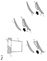
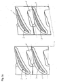
- Fig. 1 shows, for the removal of the required quantities of fluid usually slots are provided on the hub or housing wall, which are arranged in unbladed areas between two rows of blades of the machine and extend over parts or the entirety of the circumference.
- the fluid removal device extends over portions of the circumference upstream into a row of blades.
- removal devices within the blade passage the circular, oval or otherwise geometrically simple design and due to their shape and their location in the passage have a very adverse effect on the flow in the relevant blade row and the efficiency of the entire flow machine.
- Fig. 1 the blade shown schematically is provided with the reference numeral 1, wherein the upper variants of Fig. 1 each represent side views in radial sections, while the lower representations are each sectional views in the circumferential direction.
- the wall of the housing is designated 2.
- the reference numeral 6 denotes a fluid discharge opening.
- the prior art does not yet provide an effective combination of secondary fluid delivery and favorable flow control in the fluid flow machine.
- a fluid flow machine in which recesses are provided for removing fluid between the individual stator blades, which are arranged close to the pressure side of the blade, but further away from the suction side of the blade.
- recesses are provided for removing fluid between the individual stator blades, which are arranged close to the pressure side of the blade, but further away from the suction side of the blade.
- D1 says nothing.
- the US 2003/033815 A1 shows fluid removal recesses between stator blades which extend substantially in the circumferential direction.
- the recesses are not arranged close to the suction side, so they do not orient themselves on the blade suction side.
- the US-A-3,846,038 shows recesses between the stator blades, which extend at an angle to the circumferential direction like a slot from the leading edge of the blade to a central region of the next blade.
- the recesses are in particular not arranged along or near the suction side of the blade.
- the present invention has for its object to provide on at least one row of blades of a fluid flow machine, a device for fluid removal, which achieves a Sekundärfluidrgna while avoiding the prior art and at the same time an increase in efficiency by favorable flow control.
- the prior art does not yet provide an effective combination of secondary fluid delivery and favorable flow control in the fluid flow machine.
- the present invention has for its object to provide on at least one row of blades of a fluid flow machine, a device for fluid removal, which achieves a Sekundärfluidrgna while avoiding the prior art and at the same time an increase in efficiency by favorable flow control.
- a fluid take-off device is provided on the inner or the outer wall of the turbomachine within at least one blade passage of a rotor or stator blade row, the opening of which is positioned close to the blade suction side, oriented substantially along the blade suction side and viewed in chordwise direction, an elongated shape and varying Has width.
- the Fig. 1 shows in a highly simplified representation configurations of prior art fluid sampling devices: a ring slot behind the blade row, simple holes of round or oval shape without special placement, a ring slot behind blade row with spurs into the passage.
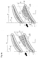
- the Fig. 2 shows a highly simplified representation of the inventive solution to a configuration of wall and blade row.
- This may be any pairing of rotor or stator blade row with a hub or housing wall of the fluid flow machine.
- the fluid removal device according to the invention is located in at least one of the passages between two blades bounded by leading and trailing edge planes.
- the blade row is, as indicated by the arrow, flows through from the left.
- the opening of the fluid removal device is located near the blade suction side and is elongated in the chordwise direction.
- Fig. 2 As well as the following figures, the fluid removal opening is designated in each case by the reference numeral 6. It is also referred to below as FE ⁇ .
- FE ⁇ fluid removal opening 6
- the blade section has the meridional length Cm.
- the flow direction is indicated by an arrow.
- a position field for the fluid removal opening 6 (FE ⁇ ) At the upstream side, the boundary is given by a circumferential line having the distance a measured from the leading edge of the profile in the meridian direction m.
- a line oriented in the circumferential direction with the distance e measured in the meridian direction m from the profile leading edge is used.
- the size of the distances a, e, and b is determined as follows (see Fig. 3 ): 0 . 2 Cm ⁇ a ⁇ 0 . 9 Cm 0 . 5 Cm ⁇ e ⁇ Cm b ⁇ 0 . 7 e - a / cos ⁇ ⁇ 2
- Reference numeral 10 denotes the pressure side of the bucket 1.
- the reference numeral 11 denotes the position field of the fluid removal opening 6.
- the reference numeral 12 denotes the radius of curvature of the bucket 1.
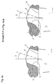
- Fig. 4a shows two favorable, within the scope of the invention possible variants of the fluid removal device with the indicated Fluident Spotifyö Stamms (FE ⁇ ) -Positionsfeld 6 and the sizes a, e and b. Characteristic of these solutions is the close orientation on the Schaufelsaugseite and on at least Parts of the fluid removal opening 6 (FE ⁇ ) provided increase in width W in blade chord direction.
- the Fig. 4c showed the in Fig. 4a . b marked section FF. Shown are examples of possible edge inclination and edge rounding at the fluid removal opening 6 (FE ⁇ ) within the scope of the invention. At the fluid removal opening 6 (FE ⁇ ) is followed by a removal channel, which is shown in a straight line in the sectional plane for easy visualization, but according to the invention may also have freely curved walls.
- the center line of the removal channel 9 adjoining the opening of the fluid removal opening 6 (FE ⁇ ) is inclined in the vicinity of the fluid removal opening 6 (FE ⁇ ) by the angle ⁇ against the perpendicular to the meridian direction m (15 ° ⁇ ⁇ 75 °).
- the Fig. 4d shows the in Fig. 4a . b marked section GG. Shown here are examples of possible in the invention edge bevel and edge rounding of the FE ⁇ .
- the removal channel adjoins the fluid removal opening 6 (FE ⁇ ), which is also shown in a straight line in this sectional plane for easy visualization, but according to the invention can have freely curved walls.
- the center line of the removal channel 9 adjoining the opening of the fluid removal opening 6 (FE ⁇ ) is inclined in the vicinity of the fluid removal opening 6 (FE ⁇ ) by the angle ⁇ against the perpendicular to the chord normal direction sn (15 ° ⁇ ⁇ 75 °).
- FE ⁇ fluid removal opening 6
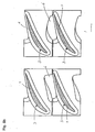
- Fig. 5a shows this for two forms according to the invention the fluid removal opening 6 (FE ⁇ ) without edge slope / rounding and aligned portions of the affected side edges.
- the Fig. 5b shows solutions with fluid removal opening 6 (FE ⁇ ) edge slope / rounding.
- FE ⁇ fluid removal opening 6
- Fig. 5c shows inventive solutions for a fluid removal opening 6 (FE ⁇ ) with edge slope / rounding, in the left half of a rectangular platform platform arrangement, in the right half for an inclined platform edge arrangement.
- FIG. 5a Inventive solutions for a row of blades with individual platforms without edge slope or edge rounding at the fluid removal opening 6
- Fig. 5b shows variants of solution according to the invention for a blade row with individual platforms with edge slope or edge rounding at the fluid removal opening 6
- Fig. 5c shows inventive solution variants for a row of blades with individual platforms and offset at the platform side edges.
Description
Die Erfindung bezieht sich auf eine Strömungsarbeitsmaschine mit Fluidentnahme gemäß dem Oberbegriff des Hauptanspruchs.The invention relates to a fluid flow machine with fluid removal according to the preamble of the main claim.
Die vorliegende Erfindung bezieht sich auf Strömungsarbeitsmaschinen wie etwa Bläser, Verdichter, Pumpen und Ventilatoren, sowohl in axialer, halbaxialer als auch in radialer Bauart. Das Arbeitsmedium oder Fluid kann gasförmig oder flüssig sein.The present invention relates to fluid flow machines such as fans, compressors, pumps and fans, in both axial, semi-axial and radial designs. The working medium or fluid may be gaseous or liquid.
Im Einzelnen betrifft die Erfindung eine Strömungsarbeitsmaschine mit zumindest einem Rotor, sie kann aber auch eine oder mehrere Stufen mit jeweils einem Rotor und einem Stator umfassen. Es existiert ein Gehäuse, welches die Durchströmung der gegebenen Rotoren und der Statoren mit einem Fluid nach außen begrenzt. Der Rotor besteht aus einer Anzahl von Schaufeln, die mit einer rotierenden Welle verbunden sind und Energie an das Arbeitsmedium abgeben. Der Rotor ist mit freiem Schaufelende oder mit Deckband am Gehäuse ausgeführt. Der Stator besteht aus einer Anzahl feststehender Schaufeln, die gehäuseseitig und/oder nabenseitig mit festem Schaufelende ausgeführt sind. Die Strömungsarbeitsmaschine kann ein- oder mehrwellig ausgeführt sein.More particularly, the invention relates to a fluid flow machine having at least one rotor, but may also include one or more stages each having a rotor and a stator. There is a housing which limits the flow of the given rotors and stators with a fluid to the outside. The rotor consists of a number of blades, which are connected to a rotating shaft and deliver energy to the working fluid. The rotor is designed with a free blade end or with shroud on the housing. The stator consists of a number of fixed blades, which are designed on the housing side and / or hub side with a fixed blade end. The turbomachine can be designed with one or more corrugations.
Eine weit verbreitete Anforderung an Strömungsarbeitsmaschinen, beispielsweise Bläsern, Verdichtern, Pumpen und Ventilatoren, besteht in der Bereitstellung von Sekundärfluidmengen an den Wandungen des Hauptströmungspfades. Wie die
In
Der in
Als nachteilig erweist sich beim Stand der Technik, dass zur Realisierung zusätzliche Baulänge aufgewendet werden muss und/oder Einbußen bezüglich des Wirkungsgrades der Strömungsarbeitmaschine hinzunehmen sind. Im Falle eines Flugtriebwerks führen übliche Fluidentnahmevorichtungen, die innerhalb des Verdichters angeordnet sind, zu Nachteilen bezüglich der Baulänge, des Baugewichts und des Kraftstoffverbrauchs.It proves to be disadvantageous in the prior art that additional structural length must be used for the realization and / or losses with regard to the efficiency of the turbomachine have to be accepted. In the case of an aircraft engine, conventional fluid intake devices disposed within the compressor lead to disadvantages in terms of length, weight and fuel consumption.
Der Stand der Technik sieht bislang keine wirkungsvolle Kombination der Sekundärfluidbereitstellung und einer günstigen Strömungsbeeinflussung in der Strömungsarbeitsmaschine vor.The prior art does not yet provide an effective combination of secondary fluid delivery and favorable flow control in the fluid flow machine.
Aus der
Die
Die
Aus der
Der vorliegenden Erfindung liegt die Aufgabe zugrunde, an mindestens einer Schaufelreihe einer Strömungsarbeitsmaschine eine Vorrichtung zur Fluidabführung zu schaffen, welche unter Vermeidung des Standes der Technik eine Sekundärfluidbereitstellung und gleichzeitig eine Wirkungsgradsteigerung durch günstige Strömungsbeeinflussung erreicht.The present invention has for its object to provide on at least one row of blades of a fluid flow machine, a device for fluid removal, which achieves a Sekundärfluidbereitstellung while avoiding the prior art and at the same time an increase in efficiency by favorable flow control.
Erfindungsgemäß wird die Aufgabe durch die Merkmalskombination des Hauptanspruchs gelöst, die Unteransprüche zeigen weitere vorteilhafte Ausgestaltungen der Erfindung.According to the invention the object is achieved by the feature combination of the main claim, the subclaims show further advantageous embodiments of the invention.
Als nachteilig erweist sich beim Stand der Technik, dass zur Realisierung zusätzliche Baulänge aufgewendet werden muss und/oder Einbußen bezüglich des Wirkungsgrades der Strömungsarbeitmaschine hinzunehmen sind. Im Falle eines Flugtriebwerks führen übliche Fluidentnahmevorichtungen, die innerhalb des Verdichters angeordnet sind, zu Nachteilen bezüglich der Baulänge, des Baugewichts und des Kraftstoffverbrauchs.It proves to be disadvantageous in the prior art that additional structural length must be used for the realization and / or losses with regard to the efficiency of the turbomachine have to be accepted. In the case of an aircraft engine, conventional fluid intake devices disposed within the compressor lead to disadvantages in terms of length, weight and fuel consumption.
Der Stand der Technik sieht bislang keine wirkungsvolle Kombination der Sekundärfluidbereitstellung und einer günstigen Strömungsbeeinflussung in der Strömungsarbeitsmaschine vor.The prior art does not yet provide an effective combination of secondary fluid delivery and favorable flow control in the fluid flow machine.
Der vorliegenden Erfindung liegt die Aufgabe zugrunde, an mindestens einer Schaufelreihe einer Strömungsarbeitsmaschine eine Vorrichtung zur Fluidabführung zu schaffen, welche unter Vermeidung des Standes der Technik eine Sekundärfluidbereitstellung und gleichzeitig eine Wirkungsgradsteigerung durch günstige Strömungsbeeinflussung erreicht.The present invention has for its object to provide on at least one row of blades of a fluid flow machine, a device for fluid removal, which achieves a Sekundärfluidbereitstellung while avoiding the prior art and at the same time an increase in efficiency by favorable flow control.
Erfindungsgemäß wird die Aufgabe durch die Merkmalskombination des Hauptanspruchs gelöst, die Unteransprüche zeigen weitere vorteilhafte Ausgestaltungen der Erfindung.According to the invention the object is achieved by the feature combination of the main claim, the subclaims show further advantageous embodiments of the invention.
Erfindungsgemäß ist an der inneren oder der äußeren Wandung der Strömungsarbeitsmaschine innerhalb mindestens einer Schaufelpassage einer Rotor- oder Statorschaufelreihe eine Fluidentnahmevorrichtung vorgesehen, deren Öffnung nahe an der Schaufelsaugseite positioniert ist, im Wesentlichen entlang der Schaufelsaugseite orientiert ist und in Profilsehnenrichtung betrachtet, eine längliche Form sowie variierende Breite besitzt.According to the invention, a fluid take-off device is provided on the inner or the outer wall of the turbomachine within at least one blade passage of a rotor or stator blade row, the opening of which is positioned close to the blade suction side, oriented substantially along the blade suction side and viewed in chordwise direction, an elongated shape and varying Has width.
Im Folgenden wird die Erfindung anhand von Ausführungsbeispielen in Verbindung mit den Figuren beschrieben. Dabei zeigt:
- Fig. 1
- eine schematische Darstellung des Standes der Technik;
- Fig. 2
- eine schematische Darstellung des erfindungsgemäßen Grundkonzeptes;
- Fig. 3
- eine Definition der Fluidentnahmeöffnung;
- Fig. 4a
- erfindungsgemäße Lösungen;
- Fig. 4b
- erfindungsgemäße Lösungen;
- Fig. 4c
- erfindungsgemäße Lösungen, Schnitt F-F in
Fig. 4a ,b; - Fig. 4d
- erfindungsgemäße Lösungen, Schnitt G-G in
Fig. 4a ,b; - Fig. 5a
- erfindungsgemäße Lösungen für eine Schaufelreihe mit Einzelplattformen, ohne Kantenschräge/-rundung an der Fluidentnahmeöffnung;
- Fig. 5b
- erfindungsgemäße Lösungen für eine Schaufelreihe mit Einzelplattformen, mit Kantenschräge/-rundung an der Fluidentnahmeöffnung;
- Fig. 5c
- erfindungsgemäße Lösungen für eine Schaufelreihe mit Einzelplattformen und Versatz an den Plattformseitenkanten.
- Fig. 1
- a schematic representation of the prior art;
- Fig. 2
- a schematic representation of the basic concept of the invention;
- Fig. 3
- a definition of the fluid removal opening;
- Fig. 4a
- solutions according to the invention;
- Fig. 4b
- solutions according to the invention;
- Fig. 4c
- solutions according to the invention, section FF in
Fig. 4a , B; - Fig. 4d
- solutions according to the invention, section GG in
Fig. 4a , B; - Fig. 5a
- inventive solutions for a row of blades with individual platforms, without edge slope / rounding at the fluid removal opening;
- Fig. 5b
- inventive solutions for a row of blades with individual platforms, with edge slope / rounding at the fluid removal opening;
- Fig. 5c
- inventive solutions for a row of blades with individual platforms and offset at the platform side edges.
Die
Die
In
In ![]()
![]()
![]()
![]()
![]()
![]()
Die in Umfangsrichtung gemessene Weite W der Fluidentnahmeöffnung 6 (FEÖ) variiert abweichend von einem konstanten Verlauf als Funktion der Meridiankoordinate: W = f(m).The width W measured in the circumferential direction of the fluid removal opening 6 (FEÖ) varies differently from a constant course as a function of the meridian coordinate: W = f (m).
Schließlich ist es besonders vorteilhaft, die der Strömung zugewandten Ränder der Fluidentnahmeöffnung 6 (FEÖ) mit einer Schräge 4 oder einer Rundung 5 zu versehen. Erfindungsgemäß werden gegebenenfalls jene Ränder der Fluidentnahmeöffnung 6 (FEÖ) mit einer Schräge 4 oder Rundung 5 versehen, deren Randnormale 8 mit der Profilsehne 7 des Wandschaufelschnittes einen Winkel α zwischen 70° und 250° einschließt (70° < α < 250°). Als Schräge/Rundung sind erfindungsgemäß auch Kantenphasen sowie längere stromauf reichende Einströmrampen zu verstehen.Finally, it is particularly advantageous to provide the flow-facing edges of the fluid removal opening 6 (FEÖ) with a
Weiterhin zeigt die
Die
Wie in
Die
Die Mittellinie des sich an die Öffnung der Fluidentnahmeöffnung 6 (FEÖ) anschließende Entnahmekanals 9 ist in Umgebung der Fluidentnahmeöffnung 6 (FEÖ) um den Winkel β gegen die Senkrechte zur Meridianrichtung m geneigt (15° < β < 75°).The center line of the
Die
Erfindungsgemäß ist es vorteilhaft, bei Konstruktionen mit Schaufeleinzelplattformen die Fluidentnahmeöffnung 6 (FEÖ) mit Hilfe der Seitenflanken zweier benachbarter Plattformen zu bilden. Die
Weiterhin ist es erfindungsgemäß besonders vorteilhaft, bei Konstruktionen mit Schaufeleinzelplattformen die Fluidentnahmeöffnung 6 (FEÖ) mit Hilfe der Seitenflanken zweier benachbarter Plattformen zu bilden, deren Teilabschnitte der betroffenen Seitenflanken nicht fluchten, sondern parallel gegeneinander versetzt ausgeführt sind. Die
Im Einzelnen zeigt die
Im Rahmen der Erfindung ergeben sich somit insbesondere folgende Vorteile:In the context of the invention, the following advantages thus result in particular:
Bei der erfindungsgemäßen Fluidentnahmeöffnung wird eine Sekundärfluidbereitstellung in Strömungsarbeitsmaschinen ermöglicht, die gleichzeitig eine positive Beeinflussung der Schaufelumströmung innerhalb des Hauptströmungspfades erlaubt. Dies ist bei unterschiedlichsten Arten von Strömungsarbeitsmaschinen wie Bläsern, Verdichtern, Pumpen und Ventilatoren möglich. Am Beispiel eines 6-stufigen Triebwerkverdichters gemessen ist pro betroffener Schaufelreihe eine Verbesserung des Verdichtergesamtwirkungsgrades von 0,2% bis 0,30% zu beziffern.In the fluid removal opening according to the invention, provision of a secondary fluid in flow machines is made possible, which at the same time allows positive influencing of the blade flow within the main flow path. This is possible with a wide variety of types of flow machines such as fans, compressors, pumps and fans. Measured by the example of a 6-stage engine compressor, an improvement of the compressor overall efficiency of 0.2% to 0.30% is to be quantified for each blade row concerned.
- 11
- Schaufelshovel
- 22
- Gehäuse (Wand)Housing (wall)
- 33
- Saugseitesuction
- 44
- Randschrägebevel
- 55
- Öffnungopening
- 66
- FluidentnahmeöffnungFluid removal opening
Claims (6)
- Fluid-flow machine with fluid removal, with at least one stator or at least one rotor, with the stator being provided with stationary vanes (1) and the rotor including several rotor blades attached to a rotating shaft, with a casing (2) confining the passage of fluid through the rotor or the stator in the outward direction, characterized in that, on an inner or an outer wall of the fluid-flow machine within at least one blade passage of a rotor blade or a stator vane row a fluid removal opening (6) is provided, which is positioned in the proximity of the blade suction side and oriented essentially along the blade suction side and - as viewed in the profile chord direction - has an elongated shape and is of varying width,
with the possibilities for designing the fluid removal opening (6) being limited - in a plane including the meridional direction (m) and the circumferential direction (u) - on the side facing the inflow by a line running in the circumferential direction with the distance (a) from the profile leading edge of the blade (1) measured in the meridional direction (m) and on the side facing away from the inflow by a line oriented in the circumferential direction with the distance (e) from the profile leading edge of the blade (1) measured in the meridional direction (m) and on the side facing the nearest blade profile by a border line running parallel to the profile chord (7) positioned against the pressure side at a distance (b) measured in the circumferential direction (u),
with the profile chord of the blade section extending at an angle (λ) against the meridional direction (m), with the sizes of the distances a, e and b being determined as follows:


with Cm being the meridional length of the blade section,
with a width (W) of the fluid removal opening (6) as measured in the circumferential direction not being constant, but varying freely as a function of the meridional coordinate (m), resulting in the following equation:
- Fluid-flow machine in accordance with Claim 1, characterized in that the edges of the fluid removal opening (6) are provided with a chamfer or radius whose edge normal (8) includes an angle α between 70° and 250° with the profile chord (7) of the wall blade section.
- Fluid-flow machine in accordance with Claim 1 or 2, characterized in that at least one edge of the fluid removal opening (6) is provided with an edge chamfer (4).
- Fluid-flow machine in accordance with Claim 1 or 2, characterized in that at least one edge of the fluid removal opening (6) is provided with a radius (5).
- Fluid-flow machine in accordance with one of the Claims 1 to 4, characterized in that a center line of a removal duct (9) connecting to the fluid removal opening (6) is inclined in the environment of the fluid removal opening (6) by an angle β to the normal on the meridional direction m, resulting in the following equation:

- Fluid-flow machine in accordance with one of the Claims 1 to 5, characterized in that a center line of a removal duct (9) connecting to the fluid removal opening (6) is inclined in the environment of the fluid removal opening (6) by an angle γ to the normal on the chordal normal direction sn, resulting in the following equation:

Applications Claiming Priority (1)
| Application Number | Priority Date | Filing Date | Title |
|---|---|---|---|
| DE102004043036A DE102004043036A1 (en) | 2004-09-06 | 2004-09-06 | Fluid flow machine with fluid removal |
Publications (3)
| Publication Number | Publication Date |
|---|---|
| EP1632662A2 EP1632662A2 (en) | 2006-03-08 |
| EP1632662A3 EP1632662A3 (en) | 2008-10-01 |
| EP1632662B1 true EP1632662B1 (en) | 2013-10-09 |
Family
ID=35447463
Family Applications (1)
| Application Number | Title | Priority Date | Filing Date |
|---|---|---|---|
| EP05018097.5A Expired - Fee Related EP1632662B1 (en) | 2004-09-06 | 2005-08-19 | Turbomachine with bleeding |
Country Status (3)
| Country | Link |
|---|---|
| US (1) | US7594793B2 (en) |
| EP (1) | EP1632662B1 (en) |
| DE (1) | DE102004043036A1 (en) |
Cited By (1)
| Publication number | Priority date | Publication date | Assignee | Title |
|---|---|---|---|---|
| CN111412181A (en) * | 2020-04-09 | 2020-07-14 | 中国航发沈阳发动机研究所 | Gas-entraining structure of gas compressor and drainage groove thereof |
Families Citing this family (22)
| Publication number | Priority date | Publication date | Assignee | Title |
|---|---|---|---|---|
| DE102004055439A1 (en) | 2004-11-17 | 2006-05-24 | Rolls-Royce Deutschland Ltd & Co Kg | Fluid flow machine with dynamic flow control |
| US8292567B2 (en) * | 2006-09-14 | 2012-10-23 | Caterpillar Inc. | Stator assembly including bleed ports for turbine engine compressor |
| US7661924B2 (en) * | 2007-03-28 | 2010-02-16 | General Electric Company | Method and apparatus for assembling turbine engines |
| FR2914705B1 (en) * | 2007-04-06 | 2012-04-27 | Snecma | TURBOMACHINE COMPRESSOR WITH AIR LEAK HOLES |
| DE102007037924A1 (en) | 2007-08-10 | 2009-02-12 | Rolls-Royce Deutschland Ltd & Co Kg | Turbomachine with Ringkanalwandausnehmung |
| DE102008011644A1 (en) | 2008-02-28 | 2009-09-03 | Rolls-Royce Deutschland Ltd & Co Kg | Housing structuring for axial compressor in the hub area |
| DE102008014957A1 (en) * | 2008-03-19 | 2009-09-24 | Rolls-Royce Deutschland Ltd & Co Kg | Gas turbine compressor with bleed air extraction |
| DE102008031982A1 (en) | 2008-07-07 | 2010-01-14 | Rolls-Royce Deutschland Ltd & Co Kg | Turbomachine with groove at a trough of a blade end |
| DE102008037154A1 (en) | 2008-08-08 | 2010-02-11 | Rolls-Royce Deutschland Ltd & Co Kg | Turbomachine |
| EP2184442A1 (en) * | 2008-11-11 | 2010-05-12 | ALSTOM Technology Ltd | Airfoil fillet |
| EP2224096A1 (en) * | 2009-02-27 | 2010-09-01 | Alstom Technology Ltd | Steam turbine and method for extracting moisture from a steam turbine |
| FR2958694B1 (en) * | 2010-04-07 | 2014-04-18 | Snecma | ENGINE COMPRESSOR, IN PARTICULAR AIRCRAFT TURBOJET ENGINE, EQUIPPED WITH AN AIR-TESTING SYSTEM |
| GB201015029D0 (en) * | 2010-09-10 | 2010-10-20 | Rolls Royce Plc | Gas turbine engine |
| JP6039059B2 (en) * | 2012-05-02 | 2016-12-07 | ゲーコーエヌ エアロスペース スウェーデン アーベー | Gas turbine engine support structure |
| US9528391B2 (en) | 2012-07-17 | 2016-12-27 | United Technologies Corporation | Gas turbine engine outer case with contoured bleed boss |
| US20140154068A1 (en) * | 2012-09-28 | 2014-06-05 | United Technologies Corporation | Endwall Controuring |
| US20140093355A1 (en) * | 2012-09-28 | 2014-04-03 | United Technologies Corporation | Extended indentation for a fastener within an air flow |
| JP6037996B2 (en) * | 2013-10-17 | 2016-12-07 | 三菱重工業株式会社 | Compressor and gas turbine |
| US10196982B2 (en) * | 2015-11-04 | 2019-02-05 | General Electric Company | Gas turbine engine having a flow control surface with a cooling conduit |
| US10227930B2 (en) | 2016-03-28 | 2019-03-12 | General Electric Company | Compressor bleed systems in turbomachines and methods of extracting compressor airflow |
| JP7439285B2 (en) | 2020-09-28 | 2024-02-27 | 三菱重工業株式会社 | steam turbine |
| US11725530B1 (en) * | 2022-05-20 | 2023-08-15 | General Electric Company | Offtake scoops for bleed pressure recovery in gas turbine engines |
Family Cites Families (42)
| Publication number | Priority date | Publication date | Assignee | Title |
|---|---|---|---|---|
| DE889506C (en) | 1940-09-25 | 1953-09-10 | Versuchsanstalt Fuer Luftfahrt | Flow machine with boundary layer suction |
| GB619722A (en) | 1946-12-20 | 1949-03-14 | English Electric Co Ltd | Improvements in and relating to boundary layer control in fluid conduits |
| US2933238A (en) * | 1954-06-24 | 1960-04-19 | Edward A Stalker | Axial flow compressors incorporating boundary layer control |
| GB799675A (en) | 1955-10-13 | 1958-08-13 | Bristol Aeroengines Ltd | Improvements in or relating to axial flow gas compressors and turbines |
| US3066912A (en) * | 1961-03-28 | 1962-12-04 | Gen Electric | Turbine erosion protective device |
| CH437614A (en) | 1963-07-02 | 1967-11-30 | Moravec Zdenek | Turbo machine with reduced noise generation |
| GB987625A (en) * | 1963-10-14 | 1965-03-31 | Rolls Royce | Improvements in or relating to axial flow compressors, for example for aircraft gas turbine engines |
| US3572960A (en) * | 1969-01-02 | 1971-03-30 | Gen Electric | Reduction of sound in gas turbine engines |
| DE1938132A1 (en) * | 1969-07-26 | 1971-01-28 | Daimler Benz Ag | Guide vanes of axial compressors |
| FR2166494A5 (en) * | 1971-12-27 | 1973-08-17 | Onera (Off Nat Aerospatiale) | |
| FR2248732A5 (en) * | 1973-10-23 | 1975-05-16 | Onera (Off Nat Aerospatiale) | |
| US4155680A (en) * | 1977-02-14 | 1979-05-22 | General Electric Company | Compressor protection means |
| FR2491549B1 (en) * | 1980-10-08 | 1985-07-05 | Snecma | DEVICE FOR COOLING A GAS TURBINE, BY TAKING AIR FROM THE COMPRESSOR |
| DE3407945A1 (en) * | 1984-03-03 | 1985-09-05 | MTU Motoren- und Turbinen-Union München GmbH, 8000 München | METHOD AND MEANS FOR AVOIDING THE DEVELOPMENT OF TITANIUM FIRE |
| US5008886A (en) * | 1989-01-27 | 1991-04-16 | Digital Equipment Corporation | Read-modify-write operation |
| US5020970A (en) * | 1989-07-13 | 1991-06-04 | Dresser-Rand Company | Fluid-handling, bladed rotor |
| US5059093A (en) * | 1990-06-07 | 1991-10-22 | United Technologies Corporation | Compressor bleed port |
| US5203162A (en) * | 1990-09-12 | 1993-04-20 | United Technologies Corporation | Compressor bleed manifold for a gas turbine engine |
| JPH04132899A (en) * | 1990-09-25 | 1992-05-07 | Mitsubishi Heavy Ind Ltd | Axial blower |
| US5209633A (en) * | 1990-11-19 | 1993-05-11 | General Electric Company | High pressure compressor flowpath bleed valve extraction slot |
| KR100198721B1 (en) | 1991-01-30 | 1999-06-15 | 레비스 스테픈 이 | Rotor case treatment |
| US5327716A (en) * | 1992-06-10 | 1994-07-12 | General Electric Company | System and method for tailoring rotor tip bleed air |
| US5480284A (en) * | 1993-12-20 | 1996-01-02 | General Electric Company | Self bleeding rotor blade |
| US5562404A (en) | 1994-12-23 | 1996-10-08 | United Technologies Corporation | Vaned passage hub treatment for cantilever stator vanes |
| US5607284A (en) | 1994-12-29 | 1997-03-04 | United Technologies Corporation | Baffled passage casing treatment for compressor blades |
| US5762034A (en) * | 1996-01-16 | 1998-06-09 | Board Of Trustees Operating Michigan State University | Cooling fan shroud |
| DE19632207A1 (en) * | 1996-08-09 | 1998-02-12 | Bmw Rolls Royce Gmbh | Process for preventing laminar boundary layer separation on turbomachine blades |
| US6109868A (en) * | 1998-12-07 | 2000-08-29 | General Electric Company | Reduced-length high flow interstage air extraction |
| US6574965B1 (en) * | 1998-12-23 | 2003-06-10 | United Technologies Corporation | Rotor tip bleed in gas turbine engines |
| US6302640B1 (en) * | 1999-11-10 | 2001-10-16 | Alliedsignal Inc. | Axial fan skip-stall |
| DE10135003C1 (en) * | 2001-07-18 | 2002-10-02 | Mtu Aero Engines Gmbh | Compressor housing structure in axially, through-flowing moving blade ring for use in pumps |
| US6585479B2 (en) * | 2001-08-14 | 2003-07-01 | United Technologies Corporation | Casing treatment for compressors |
| US6550254B2 (en) * | 2001-08-17 | 2003-04-22 | General Electric Company | Gas turbine engine bleed scoops |
| US6663346B2 (en) * | 2002-01-17 | 2003-12-16 | United Technologies Corporation | Compressor stator inner diameter platform bleed system |
| GB0206880D0 (en) * | 2002-03-23 | 2002-05-01 | Rolls Royce Plc | A vane for a rotor arrangement for a gas turbine engine |
| DE10233032A1 (en) * | 2002-07-20 | 2004-01-29 | Rolls-Royce Deutschland Ltd & Co Kg | Fluid flow machine with integrated fluid circulation system |
| ATE325939T1 (en) * | 2002-08-23 | 2006-06-15 | Mtu Aero Engines Gmbh | RECIRCULATION STRUCTURE FOR TURBO COMPRESSORS |
| DE10330084B4 (en) | 2002-08-23 | 2010-06-10 | Mtu Aero Engines Gmbh | Recirculation structure for turbocompressors |
| DE10355240A1 (en) * | 2003-11-26 | 2005-07-07 | Rolls-Royce Deutschland Ltd & Co Kg | Fluid flow machine with fluid removal |
| US7097414B2 (en) * | 2003-12-16 | 2006-08-29 | Pratt & Whitney Rocketdyne, Inc. | Inducer tip vortex suppressor |
| GB2413158B (en) * | 2004-04-13 | 2006-08-16 | Rolls Royce Plc | Flow control arrangement |
| DE102004030597A1 (en) * | 2004-06-24 | 2006-01-26 | Rolls-Royce Deutschland Ltd & Co Kg | Turbomachine with external wheel jet generation at the stator |
-
2004
- 2004-09-06 DE DE102004043036A patent/DE102004043036A1/en not_active Withdrawn
-
2005
- 2005-08-19 EP EP05018097.5A patent/EP1632662B1/en not_active Expired - Fee Related
- 2005-09-06 US US11/218,521 patent/US7594793B2/en not_active Expired - Fee Related
Cited By (1)
| Publication number | Priority date | Publication date | Assignee | Title |
|---|---|---|---|---|
| CN111412181A (en) * | 2020-04-09 | 2020-07-14 | 中国航发沈阳发动机研究所 | Gas-entraining structure of gas compressor and drainage groove thereof |
Also Published As
| Publication number | Publication date |
|---|---|
| EP1632662A3 (en) | 2008-10-01 |
| US7594793B2 (en) | 2009-09-29 |
| DE102004043036A1 (en) | 2006-03-09 |
| EP1632662A2 (en) | 2006-03-08 |
| US20060051199A1 (en) | 2006-03-09 |
Similar Documents
| Publication | Publication Date | Title |
|---|---|---|
| EP1632662B1 (en) | Turbomachine with bleeding | |
| EP2025945B1 (en) | Flow working machine with ring canal wall fitting | |
| EP2003292B1 (en) | Fluid working machine having blade shroud with overhang | |
| EP2138727B1 (en) | Blade shrouds with outlet | |
| EP2194232B1 (en) | Turbo engine with side wall boundary layer barrier | |
| EP2463480B1 (en) | Blade with hybrid airfoil | |
| EP1927723B1 (en) | Stator stage of an axial compressor in a flow engine with transverse fins to increase the action | |
| EP2696029B1 (en) | Blade row with side wall contours and fluid flow engine | |
| EP2226510B1 (en) | Turbo compressor or pump with fluid injection to influence the boundary layer | |
| DE10327574B4 (en) | Impeller for a fuel pump | |
| EP2761137B1 (en) | Blade of a row of rotor blades or stator blades for use in a turbomachine | |
| EP2275643B1 (en) | Engine blade with excess front edge loading | |
| EP1657401A2 (en) | Turbo machine blade with an extended profile chord length in its tip and root regions | |
| EP0916812A1 (en) | Final stage for an axial turbine | |
| EP1760321A2 (en) | Blade for turbomachine | |
| EP2947270B1 (en) | Rotor series group | |
| EP1759090A1 (en) | Vane comprising a transition zone | |
| EP2538024A1 (en) | Blade of a turbomaschine | |
| EP2180195A2 (en) | Turbo machine with tip clearance control | |
| EP3078804A1 (en) | Shroud assembly of a row of stator or rotor blades and corresponding turbine | |
| WO2017140756A1 (en) | Mixed-flow turbine wheel of a turbocharger, and exhaust gas turbine comprising a turbine wheel of said type | |
| EP2607625B1 (en) | Turbomachine and stage of turbomachine | |
| DE10205363A1 (en) | gas turbine | |
| EP3375977A1 (en) | Contouring of a platform in an airfoil cascade | |
| EP3404211A1 (en) | Blade cascade segment for a turbine with contoured platform surface, corresponding blade cascade, blade channel, platform, turbine and aircraft engine |
Legal Events
| Date | Code | Title | Description |
|---|---|---|---|
| PUAI | Public reference made under article 153(3) epc to a published international application that has entered the european phase |
Free format text: ORIGINAL CODE: 0009012 |
|
| AK | Designated contracting states |
Kind code of ref document: A2 Designated state(s): AT BE BG CH CY CZ DE DK EE ES FI FR GB GR HU IE IS IT LI LT LU LV MC NL PL PT RO SE SI SK TR |
|
| AX | Request for extension of the european patent |
Extension state: AL BA HR MK YU |
|
| PUAL | Search report despatched |
Free format text: ORIGINAL CODE: 0009013 |
|
| AK | Designated contracting states |
Kind code of ref document: A3 Designated state(s): AT BE BG CH CY CZ DE DK EE ES FI FR GB GR HU IE IS IT LI LT LU LV MC NL PL PT RO SE SI SK TR |
|
| AX | Request for extension of the european patent |
Extension state: AL BA HR MK YU |
|
| 17P | Request for examination filed |
Effective date: 20090312 |
|
| AKX | Designation fees paid |
Designated state(s): DE FR GB |
|
| 17Q | First examination report despatched |
Effective date: 20110707 |
|
| REG | Reference to a national code |
Ref country code: DE Ref legal event code: R079 Ref document number: 502005014020 Country of ref document: DE Free format text: PREVIOUS MAIN CLASS: F02C0006080000 Ipc: F01D0005140000 |
|
| RIC1 | Information provided on ipc code assigned before grant |
Ipc: F02C 9/18 20060101ALI20130307BHEP Ipc: F01D 5/14 20060101AFI20130307BHEP Ipc: F01D 17/10 20060101ALI20130307BHEP Ipc: F04D 27/02 20060101ALI20130307BHEP |
|
| GRAP | Despatch of communication of intention to grant a patent |
Free format text: ORIGINAL CODE: EPIDOSNIGR1 |
|
| INTG | Intention to grant announced |
Effective date: 20130515 |
|
| GRAS | Grant fee paid |
Free format text: ORIGINAL CODE: EPIDOSNIGR3 |
|
| GRAA | (expected) grant |
Free format text: ORIGINAL CODE: 0009210 |
|
| AK | Designated contracting states |
Kind code of ref document: B1 Designated state(s): DE FR GB |
|
| REG | Reference to a national code |
Ref country code: GB Ref legal event code: FG4D Free format text: NOT ENGLISH |
|
| REG | Reference to a national code |
Ref country code: DE Ref legal event code: R096 Ref document number: 502005014020 Country of ref document: DE Effective date: 20131205 |
|
| REG | Reference to a national code |
Ref country code: DE Ref legal event code: R097 Ref document number: 502005014020 Country of ref document: DE |
|
| PLBE | No opposition filed within time limit |
Free format text: ORIGINAL CODE: 0009261 |
|
| STAA | Information on the status of an ep patent application or granted ep patent |
Free format text: STATUS: NO OPPOSITION FILED WITHIN TIME LIMIT |
|
| 26N | No opposition filed |
Effective date: 20140710 |
|
| REG | Reference to a national code |
Ref country code: DE Ref legal event code: R097 Ref document number: 502005014020 Country of ref document: DE Effective date: 20140710 |
|
| REG | Reference to a national code |
Ref country code: FR Ref legal event code: PLFP Year of fee payment: 12 |
|
| REG | Reference to a national code |
Ref country code: FR Ref legal event code: PLFP Year of fee payment: 13 |
|
| REG | Reference to a national code |
Ref country code: FR Ref legal event code: PLFP Year of fee payment: 14 |
|
| PGFP | Annual fee paid to national office [announced via postgrant information from national office to epo] |
Ref country code: DE Payment date: 20190828 Year of fee payment: 15 Ref country code: FR Payment date: 20190826 Year of fee payment: 15 |
|
| PGFP | Annual fee paid to national office [announced via postgrant information from national office to epo] |
Ref country code: GB Payment date: 20190827 Year of fee payment: 15 |
|
| REG | Reference to a national code |
Ref country code: DE Ref legal event code: R082 Ref document number: 502005014020 Country of ref document: DE |
|
| REG | Reference to a national code |
Ref country code: DE Ref legal event code: R119 Ref document number: 502005014020 Country of ref document: DE |
|
| GBPC | Gb: european patent ceased through non-payment of renewal fee |
Effective date: 20200819 |
|
| PG25 | Lapsed in a contracting state [announced via postgrant information from national office to epo] |
Ref country code: DE Free format text: LAPSE BECAUSE OF NON-PAYMENT OF DUE FEES Effective date: 20210302 Ref country code: FR Free format text: LAPSE BECAUSE OF NON-PAYMENT OF DUE FEES Effective date: 20200831 |
|
| PG25 | Lapsed in a contracting state [announced via postgrant information from national office to epo] |
Ref country code: GB Free format text: LAPSE BECAUSE OF NON-PAYMENT OF DUE FEES Effective date: 20200819 |