EP1926641B1 - Scheibenwischvorrichtung, insbesondere für ein kraftfahrzeug - Google Patents
Scheibenwischvorrichtung, insbesondere für ein kraftfahrzeug Download PDFInfo
- Publication number
- EP1926641B1 EP1926641B1 EP06778082A EP06778082A EP1926641B1 EP 1926641 B1 EP1926641 B1 EP 1926641B1 EP 06778082 A EP06778082 A EP 06778082A EP 06778082 A EP06778082 A EP 06778082A EP 1926641 B1 EP1926641 B1 EP 1926641B1
- Authority
- EP
- European Patent Office
- Prior art keywords
- wiper
- wiper device
- wiper shaft
- windscreen wiper
- plane
- Prior art date
- Legal status (The legal status is an assumption and is not a legal conclusion. Google has not performed a legal analysis and makes no representation as to the accuracy of the status listed.)
- Not-in-force
Links
- 238000006073 displacement reaction Methods 0.000 claims description 4
- 239000002184 metal Substances 0.000 description 3
- 208000027418 Wounds and injury Diseases 0.000 description 2
- 230000006378 damage Effects 0.000 description 2
- 208000014674 injury Diseases 0.000 description 2
- 238000004519 manufacturing process Methods 0.000 description 2
- 238000010521 absorption reaction Methods 0.000 description 1
- 239000000919 ceramic Substances 0.000 description 1
- 238000010276 construction Methods 0.000 description 1
- 230000007797 corrosion Effects 0.000 description 1
- 238000005260 corrosion Methods 0.000 description 1
- 238000013016 damping Methods 0.000 description 1
- 230000001419 dependent effect Effects 0.000 description 1
- 238000004512 die casting Methods 0.000 description 1
- 238000002347 injection Methods 0.000 description 1
- 239000007924 injection Substances 0.000 description 1
- 238000001746 injection moulding Methods 0.000 description 1
- 238000000034 method Methods 0.000 description 1
Images


Classifications
-
- B—PERFORMING OPERATIONS; TRANSPORTING
- B60—VEHICLES IN GENERAL
- B60S—SERVICING, CLEANING, REPAIRING, SUPPORTING, LIFTING, OR MANOEUVRING OF VEHICLES, NOT OTHERWISE PROVIDED FOR
- B60S1/00—Cleaning of vehicles
- B60S1/02—Cleaning windscreens, windows or optical devices
- B60S1/04—Wipers or the like, e.g. scrapers
- B60S1/0488—Wiper arrangement for crash protection or impact absorption
-
- B—PERFORMING OPERATIONS; TRANSPORTING
- B60—VEHICLES IN GENERAL
- B60S—SERVICING, CLEANING, REPAIRING, SUPPORTING, LIFTING, OR MANOEUVRING OF VEHICLES, NOT OTHERWISE PROVIDED FOR
- B60S1/00—Cleaning of vehicles
- B60S1/02—Cleaning windscreens, windows or optical devices
- B60S1/04—Wipers or the like, e.g. scrapers
- B60S1/043—Attachment of the wiper assembly to the vehicle
- B60S1/0441—Attachment of the wiper assembly to the vehicle characterised by the attachment means
- B60S1/0444—Attachment of the wiper assembly to the vehicle characterised by the attachment means comprising vibration or noise absorbing means
-
- B—PERFORMING OPERATIONS; TRANSPORTING
- B60—VEHICLES IN GENERAL
- B60S—SERVICING, CLEANING, REPAIRING, SUPPORTING, LIFTING, OR MANOEUVRING OF VEHICLES, NOT OTHERWISE PROVIDED FOR
- B60S1/00—Cleaning of vehicles
- B60S1/02—Cleaning windscreens, windows or optical devices
- B60S1/04—Wipers or the like, e.g. scrapers
- B60S1/32—Wipers or the like, e.g. scrapers characterised by constructional features of wiper blade arms or blades
- B60S1/34—Wiper arms; Mountings therefor
- B60S1/3488—Means for mounting wiper arms onto the vehicle
- B60S1/3493—Means for mounting the wiper shaft in the wiper bearing
Definitions
- the invention relates to a windshield wiper device, in particular for a motor vehicle, according to the preamble of the independent claim.
- windscreen wiper devices for example from the DE-A-10255775 known, which have a wiper bearing with a bearing housing in which a wiper shaft is mounted and fixed axially by means of an element.
- the wiper shaft carries at its free, first end a wiper arm, at the free end of a wiper blade can be attached.
- the axial fixation is designed such that the element is deformed upon application of force to the wiper arm or to the first end of the wiper arm shaft with energy absorption. If, in the event of an accident, a pedestrian collides with the wiper arms or the wiper shaft of the windscreen wiper device, they can recede, thereby avoiding or at least reducing injuries to the pedestrian.
- the element is capable of absorbing energy also prevents the pedestrian from striking the vehicle body with all the energy of the impact.
- a spring is provided as an element for axial fixation, which allows the impact of a pedestrian on the free, first end of the wiper shaft, a retreat of the wiper shaft and thereby absorbs energy from the impact.
- predetermined breaking elements are also provided, which axially stabilize the wiper shaft in normal operation.
- the windshield wiper device according to the invention with the features of the main claim has the advantage that the element is designed as a bridge element. In this way, the force needed to allow the wiper shaft to recede can be accurately metered and remains constant throughout the life of the windshield wiper device. Moreover, such a design is simple and inexpensive to manufacture.
- the wiper shaft has a shoulder and the bridge element first between the bearing housing and the approach arranged to allow stable axial fixation in normal operation.
- the approach is essentially disc-shaped and surrounds the wiper shaft.
- a component can be saved if the approach is formed integrally with that of the wiper shaft.
- the bridge element also has at least three planes coaxial with the wiper shaft, which are connected by connecting webs.
- the connecting webs extend obliquely to the wiper shaft.
- connecting webs are arranged parallel to the wiper shaft.
- the connecting webs do not overlap in a projection onto a plane parallel to the wiper shaft in order to enable a simple and cost-effective possibility of producing the bridge element.
- the bridge element has a predetermined breaking point.
- the predetermined breaking point is arranged in at least one plane, in particular in one of the center planes.
- each level is connected by at least three, in particular four, connecting webs with the respective adjacent level and for each connecting web at least one predetermined breaking point in the adjacent, not marginal level is provided to a slight retreat of the wiper shaft To allow impact of a pedestrian.
- the wiper shaft is drivable by a drive crank, which is formed integrally with the approach or even serves as an approach.
- the bridge element is executed protected against corrosion, in particular made of plastic.
- a long life and a safe function is achieved in that the bearing housing, the wiper shaft or the approach have securing means which prevent twisting or displacement of the bridge element.
- the bridge element may be integrally formed with the bearing housing.
- FIG. 1 a windshield wiper device 10 according to the invention is shown in a perspective view.
- This essentially comprises a support tube 12 which carries a wiper bearing 14 at the ends of its longitudinal extent. Furthermore, a motor support 16, which carries a wiper motor 18, is fastened to the carrier tube 12.
- This wiper motor 18 drives via push rods 20 wiper shafts 22, which are mounted in the bearing housing 24 of the wiper bearing 14.
- the push rod 20 is articulated to a drive crank 32, which in turn is rotatably connected to the wiper shaft 22.
- the wiper bearing 14 also has a fastening eye 15, which is arranged on the side facing away from the carrier tube of the wiper bearing. In the mounting eye 15 sits a rubber sleeve 17 for vibration damping of the system.
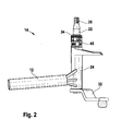
- FIG. 2 is a wiper bearing 14 of a windshield wiper device 10 according to the invention shown in detail in a perspective side view.
- the wiper shaft 22 is mounted in a substantially tubular bearing housing 24 of the wiper bearing 14. It has a first end 26 on which it is rotatably connected to a, not shown here for reasons of clarity, wiper arm.
- This first end 26 consists of a tapered portion, which opens in a thread to the end of the wiper shaft 22.
- the drive crank 32 is arranged in the region of the wiper shaft 22, which faces away from the first end 26 of the wiper shaft 22 along the longitudinal extent. This drive crank 32 is in turn connected to the push rod 20 (FIG. FIG. 1 ) hingedly connected.
- the wiper shaft on a projection 34 which is formed as a disc and is fixed axially on the wiper shaft 22.
- the lug 34 may also be integrally formed with the wiper shaft 22 or formed by the drive crank 32 itself, if these - as in FIG. 1 shown - in the region of the first end 26 of the wiper shaft 22 is arranged.
- the projection 34 is formed as a radially and axially movable disc whose axial mobility is limited by the drive crank 32. In principle, the approach 34 but also from one at least partially annular recess or an opening in which a snap ring or a pin or bolt or any other retaining element is inserted.
- the wiper shaft 22 protrudes from an end face of the bearing housing 24, which faces the first end 26, out. Between the projection 34 and the end face of the bearing housing 24, a bridge element is attached as an element 40. To support the element 40, a metal or plastic disk can also be arranged as a thrust washer on the end face of the bearing housing.
- the drive crank 32 On the front side of the bearing housing 24, which faces away from the bridge element 40, the drive crank 32 is non-rotatably connected to the wiper shaft 22.
- the drive crank 32 is in this case directly on the end face of the bearing housing 24, so that the wiper shaft is axially fixed by the projection 34 and the drive crank 32.
- Between the bridge element 40 facing away from the end face of the bearing housing 24 and the drive crank 32 may also be provided one or more thrust washers.
- the drive crank 32 arranged in the region of the first end 26 of the wiper shaft 22, it can be provided for axial fixation at the end remote from the first end 26 of the wiper shaft 22, a special fixing element.
- the drive crank 32 can then replace the projection 34.
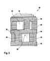
- the bridge member 40 is shown in detail with a portion of the wiper shaft 22 and the projection 34 in a side view.
- the bridge element 40 essentially comprises three planes (42, 44, 46), which are essentially annular in shape and nestle around the wiper shaft 22 in the assembled state.
- connecting webs 48 are arranged, which extend perpendicularly from the bottom-side plane 42, parallel to the wiper shaft 22, and are of substantially parallelepiped shape.
- These connecting webs 48 carry the median plane 44. Offset from the connecting webs, which extend from the bottom-side plane 42, further connecting webs 48 are arranged on the median plane 44.
- each plane 42, 44, 46 is connected by connecting webs 48 to the respective adjacent plane 42, 44, 46.
- For each connecting web 48 at least one predetermined breaking point 52 in the adjacent plane 44, provided that it does not form the bottom-side plane 42 or the ceiling plane 46, so no marginal level 42, 46 forms.
- predetermined breaking points 52 are arranged on all middle planes 44, as connecting webs 48 emanating from it.
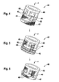
- the bridge element 40 during an impact force F, as this can occur in a colliding with the free end 26 of the wiper shaft 22 pedestrian.
- the reference numbers are the same here as in FIG. 3 selected.
- the bridge element 40 has four connecting webs 48 between in each case two adjacent planes 42, 44, 46.
- eight predetermined breaking points 52 are provided in the median plane 44, which are each between two of the eight connecting webs 48.
- the two marginal levels 42, 46 have no predetermined breaking points 52. In this way, the upper ceiling level 46, together with the connecting webs 48 extending from it, can move in the direction of the floor level 42 when the predetermined breaking points 52 break.
- the connecting webs 48 which are connected to the ceiling plane 46, slide then between the connecting webs 48, which are connected to the ground plane 42, down, whereby the overall height of the bridge element 40 is substantially reduced. Since the ceiling plane 46 forms the abutment surface for the lug 34, which is axially fixedly connected to the wiper shaft 22, the first end 26 of the wiper shaft 22 can slide down in this way, or in other words, by an impulse pushes the ceiling plane 46 with the connecting webs 48 on the median plane 44, whereby the predetermined breaking points 52 break.
- the ceiling plane 46 slides with the extending from her connecting webs 48 downwards in such a way that the connecting webs 48 which extend from the bottom-side plane 42, crown-like with the connecting webs 48 which extend from the ceiling plane 46 mesh.
- a force F greater than a predetermined force
- FIG. 7 is the wiper bearing 14 off FIG. 2 after a force F shown.
- the bridge element 40 is compressed by the retraction of the first end 26 of the wiper shaft 22 with the projection 34.
- the middle plane 44 is destroyed.
- the wiper shaft 22 has slid downwards within the bearing housing 24, so that a gap L results between the end face of the bearing housing 24 facing away from the first end 26 of the wiper shaft 22 and the drive crank 32.
- the wiper shaft 22 has thus slid down within the bearing housing 24.
- FIG. 8 a variation of the invention is shown.
- the bridge element 40 is formed integrally with the bearing housing 24.
- the end face of the wiper bearing 24 itself forms the bottom plane 42 of the bridge element 40.
- the bridge element 40 is made in one piece from plastic. Of course, a production of metal or ceramic is possible and is determined according to the required forces and Kraftverlaufsprofilen by the expert.
- the bearing housing 24 may also be formed of plastic. Just as in the bridge member 40 and the bearing housing 24 is a training as an injection molded part - even in a multi-component Injection molding - possible. A corresponding die-casting process is also suitable, in particular in the case of a construction made of metal.
- securing means for example a cam or a pin with a respective corresponding recess in the bearing housing 24 or in the bridge element 40 can also be provided. These must be arranged so that the crown-like displacement of the top surface 46 with the connecting webs 48 is not hindered by the force F.
Landscapes
- Engineering & Computer Science (AREA)
- Mechanical Engineering (AREA)
- Body Structure For Vehicles (AREA)
- Mounting Of Bearings Or Others (AREA)
- Pivots And Pivotal Connections (AREA)
Priority Applications (1)
| Application Number | Priority Date | Filing Date | Title |
|---|---|---|---|
| PL06778082T PL1926641T3 (pl) | 2005-09-09 | 2006-07-31 | Urządzenie wycieraczki do szyb, w szczególności do pojazdu mechanicznego |
Applications Claiming Priority (2)
| Application Number | Priority Date | Filing Date | Title |
|---|---|---|---|
| DE102005042847A DE102005042847A1 (de) | 2005-09-09 | 2005-09-09 | Scheibenwischvorrichtung, insbesondere für ein Kraftfahrzeug |
| PCT/EP2006/064857 WO2007028678A1 (de) | 2005-09-09 | 2006-07-31 | Scheibenwischvorrichtung, insbesondere für ein kraftfahrzeug |
Publications (2)
| Publication Number | Publication Date |
|---|---|
| EP1926641A1 EP1926641A1 (de) | 2008-06-04 |
| EP1926641B1 true EP1926641B1 (de) | 2012-09-12 |
Family
ID=37067398
Family Applications (1)
| Application Number | Title | Priority Date | Filing Date |
|---|---|---|---|
| EP06778082A Not-in-force EP1926641B1 (de) | 2005-09-09 | 2006-07-31 | Scheibenwischvorrichtung, insbesondere für ein kraftfahrzeug |
Country Status (6)
| Country | Link |
|---|---|
| US (1) | US8196253B2 (pl) |
| EP (1) | EP1926641B1 (pl) |
| CN (1) | CN101258062A (pl) |
| DE (1) | DE102005042847A1 (pl) |
| PL (1) | PL1926641T3 (pl) |
| WO (1) | WO2007028678A1 (pl) |
Families Citing this family (21)
| Publication number | Priority date | Publication date | Assignee | Title |
|---|---|---|---|---|
| DE102006027345B4 (de) * | 2006-06-13 | 2018-03-22 | Valeo Wischersysteme Gmbh | Wischanlage für Fahrzeugscheiben |
| US8516647B2 (en) * | 2009-10-14 | 2013-08-27 | Trico Products Corporation | Collapsible pivot body for a windshield wiper system |
| DE102009046203A1 (de) * | 2009-10-30 | 2011-05-12 | Robert Bosch Gmbh | Antriebseinrichtung in einer Scheibenwischvorrichtung eines Fahrzeugs |
| DE102009054830A1 (de) * | 2009-12-17 | 2011-06-22 | Robert Bosch GmbH, 70469 | Scheibenwischvorrichtung |
| US20130227809A1 (en) | 2012-02-24 | 2013-09-05 | Pylon Manufacturing Corp. | Wiper blade |
| US9457768B2 (en) | 2011-04-21 | 2016-10-04 | Pylon Manufacturing Corp. | Vortex damping wiper blade |
| WO2013016493A1 (en) | 2011-07-28 | 2013-01-31 | Pylon Manufacturing Corp. | Windshield wiper adapter, connector and assembly |
| US9108595B2 (en) | 2011-07-29 | 2015-08-18 | Pylon Manufacturing Corporation | Windshield wiper connector |
| US20130219649A1 (en) | 2012-02-24 | 2013-08-29 | Pylon Manufacturing Corp. | Wiper blade |
| DE102012211072A1 (de) * | 2012-06-27 | 2014-01-02 | Robert Bosch Gmbh | Scheibenwischervorrichtung |
| US10829092B2 (en) | 2012-09-24 | 2020-11-10 | Pylon Manufacturing Corp. | Wiper blade with modular mounting base |
| US10166951B2 (en) | 2013-03-15 | 2019-01-01 | Pylon Manufacturing Corp. | Windshield wiper connector |
| FR3016584B1 (fr) * | 2014-01-21 | 2017-08-11 | Peugeot Citroen Automobiles Sa | Dispositif de fixation d'essuie-glace |
| US9505380B2 (en) | 2014-03-07 | 2016-11-29 | Pylon Manufacturing Corp. | Windshield wiper connector and assembly |
| EP3368383B1 (en) | 2015-10-26 | 2021-08-04 | Pylon Manufacturing Corp. | Wiper blade |
| US10717414B2 (en) | 2016-05-19 | 2020-07-21 | Pylon Manufacturing Corporation | Windshield wiper blade |
| AU2017268008A1 (en) | 2016-05-19 | 2018-11-22 | Pylon Manufacturing Corp. | Windshield wiper connector |
| AU2017267978A1 (en) | 2016-05-19 | 2018-11-22 | Pylon Manufacturing Corp. | Windshield wiper connector |
| US11040705B2 (en) | 2016-05-19 | 2021-06-22 | Pylon Manufacturing Corp. | Windshield wiper connector |
| AU2017268019A1 (en) | 2016-05-19 | 2018-11-22 | Pylon Manufacturing Corp. | Windshield wiper connector |
| WO2018081791A1 (en) | 2016-10-31 | 2018-05-03 | Pylon Manufacturing Corp. | Wiper blade with cover |
Citations (1)
| Publication number | Priority date | Publication date | Assignee | Title |
|---|---|---|---|---|
| EP1809520B1 (fr) * | 2004-11-04 | 2009-08-12 | Renault s.a.s. | Dispositif d'essuie-glace pour vehicule |
Family Cites Families (9)
| Publication number | Priority date | Publication date | Assignee | Title |
|---|---|---|---|---|
| EP1263632B1 (de) * | 1998-01-29 | 2006-04-26 | Robert Bosch Gmbh | Wischeranlage |
| US6317918B1 (en) * | 1998-04-24 | 2001-11-20 | Honda Giken Kogyo Kabushiki Kaisha | Windshield wiper device for vehicle |
| DE19909970A1 (de) * | 1999-03-06 | 2000-09-07 | Bosch Gmbh Robert | Vorrichtung zum Befestigen eines Bauteils auf einer Antriebswelle einer Wischeranlage |
| US6568023B2 (en) * | 2000-12-14 | 2003-05-27 | Ford Global Technologies, L.L.C. | Wiper pivot |
| DE10242114A1 (de) | 2002-09-11 | 2004-03-25 | Robert Bosch Gmbh | Scheibenwischvorrichtung, insbesondere für ein Kraftfahrzeug |
| DE10255775A1 (de) | 2002-11-29 | 2004-06-09 | Robert Bosch Gmbh | Scheibenwischvorrichtung, insbesondere für ein Kraftfahrzeug |
| DE10255774B4 (de) * | 2002-11-29 | 2017-02-02 | Robert Bosch Gmbh | Scheibenwischvorrichtung, insbesondere für ein Kraftfahrzeug |
| DE10305309B4 (de) | 2003-02-10 | 2014-10-30 | Robert Bosch Gmbh | Befestigungseinrichtung für einen Scheibenwischerantrieb an einem Fahrzeug |
| DE10361744A1 (de) | 2003-12-29 | 2005-07-28 | Robert Bosch Gmbh | Scheibenwischvorrichtung, insbesondere für ein Kraftfahrzeug |
-
2005
- 2005-09-09 DE DE102005042847A patent/DE102005042847A1/de not_active Ceased
-
2006
- 2006-07-31 WO PCT/EP2006/064857 patent/WO2007028678A1/de active Application Filing
- 2006-07-31 US US11/997,803 patent/US8196253B2/en not_active Expired - Fee Related
- 2006-07-31 CN CNA2006800328838A patent/CN101258062A/zh active Pending
- 2006-07-31 EP EP06778082A patent/EP1926641B1/de not_active Not-in-force
- 2006-07-31 PL PL06778082T patent/PL1926641T3/pl unknown
Patent Citations (1)
| Publication number | Priority date | Publication date | Assignee | Title |
|---|---|---|---|---|
| EP1809520B1 (fr) * | 2004-11-04 | 2009-08-12 | Renault s.a.s. | Dispositif d'essuie-glace pour vehicule |
Also Published As
| Publication number | Publication date |
|---|---|
| WO2007028678A1 (de) | 2007-03-15 |
| DE102005042847A1 (de) | 2007-03-15 |
| CN101258062A (zh) | 2008-09-03 |
| EP1926641A1 (de) | 2008-06-04 |
| US8196253B2 (en) | 2012-06-12 |
| US20080222828A1 (en) | 2008-09-18 |
| PL1926641T3 (pl) | 2013-02-28 |
Similar Documents
| Publication | Publication Date | Title |
|---|---|---|
| EP1926641B1 (de) | Scheibenwischvorrichtung, insbesondere für ein kraftfahrzeug | |
| EP1263632B1 (de) | Wischeranlage | |
| EP1713668B1 (de) | Scheibenwischvorrichtung, insbesondere für ein kraftfahrzeug | |
| EP1718507B1 (de) | Scheibenwischanlage für fahrzeuge sowie befestigungselement für eine solche anlage | |
| EP2026998B1 (de) | Wischanlage für fahrzeugscheiben | |
| EP1458596B1 (de) | Befestigung einer wischeranlage | |
| EP1720746A1 (de) | Scheibenwischvorrichtung, insbesondere für ein kraftfahrzeug | |
| EP3385143B1 (de) | Anlenkungseinrichtung für eine kupplung insbesondere eines schienenfahrzeugs | |
| DE102010042374B4 (de) | Scheibenwischervorrichtung | |
| DE102004005065A1 (de) | Scheibenwischvorrichtung, insbesondere für ein Kraftfahrzeug | |
| EP1763460B1 (de) | Vorrichtung zur befestigung einer scheibenwishvorrichtung an einem kraftfahrzeug | |
| EP2167354B1 (de) | Befestigungsanordnung | |
| WO2007012551A1 (de) | Scheibenwischvorrichtung, insbesondere für ein kraftfahrzeug | |
| EP1651480B1 (de) | Befestigungsanordnung | |
| EP1567396A1 (de) | Scheibenwischvorrichtung, insbesondere für ein kraftfahrzeug | |
| DE10343572A1 (de) | Aufprallweiche Lagerung einer Antriebswelle eines Scheibenwischers an einem Fahrzeug | |
| DE10255774B4 (de) | Scheibenwischvorrichtung, insbesondere für ein Kraftfahrzeug | |
| WO2002064406A1 (de) | Wischarm | |
| EP1716026B1 (de) | Scheibenwischvorrichtung | |
| DE102007009566B4 (de) | Getriebe-Antriebseinheit mit gehäusefestem Lagerbolzen | |
| DE102006004048B4 (de) | Befestigungseinrichtung zur Verwendung bei einer Wischanlage für Fahrzeuge sowie Wischanlage | |
| DE19908888B4 (de) | Verstellbarer Rückblickspiegel, insbesondere Außenspiegel für ein Kraftfahrzeug | |
| WO2012059146A1 (de) | Kraftbegrenzungsvorrichtung, gurtaufroller mit kraftfbegrenzungsvorrichtung und verfahren zum umschalten einer kraftbegrenzungsvorrichtung | |
| WO2005085023A1 (de) | Scheibenwischvorrichtung, insbesondere für ein kraftfahrzeug | |
| DE10145209B4 (de) | Kopfstützenanordnung für ein Kraftfahrzeug |
Legal Events
| Date | Code | Title | Description |
|---|---|---|---|
| PUAI | Public reference made under article 153(3) epc to a published international application that has entered the european phase |
Free format text: ORIGINAL CODE: 0009012 |
|
| 17P | Request for examination filed |
Effective date: 20080409 |
|
| AK | Designated contracting states |
Kind code of ref document: A1 Designated state(s): CZ FR GB IT PL |
|
| RBV | Designated contracting states (corrected) |
Designated state(s): CZ FR GB IT PL |
|
| RBV | Designated contracting states (corrected) |
Designated state(s): CZ DE FR GB IT PL |
|
| RBV | Designated contracting states (corrected) |
Designated state(s): CZ DE FR GB IT PL |
|
| 17Q | First examination report despatched |
Effective date: 20090518 |
|
| GRAP | Despatch of communication of intention to grant a patent |
Free format text: ORIGINAL CODE: EPIDOSNIGR1 |
|
| DAX | Request for extension of the european patent (deleted) | ||
| GRAS | Grant fee paid |
Free format text: ORIGINAL CODE: EPIDOSNIGR3 |
|
| GRAA | (expected) grant |
Free format text: ORIGINAL CODE: 0009210 |
|
| AK | Designated contracting states |
Kind code of ref document: B1 Designated state(s): CZ DE FR GB IT PL |
|
| REG | Reference to a national code |
Ref country code: GB Ref legal event code: FG4D Free format text: NOT ENGLISH |
|
| REG | Reference to a national code |
Ref country code: DE Ref legal event code: R096 Ref document number: 502006011984 Country of ref document: DE Effective date: 20121108 |
|
| REG | Reference to a national code |
Ref country code: PL Ref legal event code: T3 |
|
| PLBE | No opposition filed within time limit |
Free format text: ORIGINAL CODE: 0009261 |
|
| STAA | Information on the status of an ep patent application or granted ep patent |
Free format text: STATUS: NO OPPOSITION FILED WITHIN TIME LIMIT |
|
| 26N | No opposition filed |
Effective date: 20130613 |
|
| REG | Reference to a national code |
Ref country code: DE Ref legal event code: R097 Ref document number: 502006011984 Country of ref document: DE Effective date: 20130613 |
|
| REG | Reference to a national code |
Ref country code: FR Ref legal event code: PLFP Year of fee payment: 10 |
|
| PGFP | Annual fee paid to national office [announced via postgrant information from national office to epo] |
Ref country code: GB Payment date: 20150724 Year of fee payment: 10 |
|
| PGFP | Annual fee paid to national office [announced via postgrant information from national office to epo] |
Ref country code: FR Payment date: 20150730 Year of fee payment: 10 |
|
| PGFP | Annual fee paid to national office [announced via postgrant information from national office to epo] |
Ref country code: IT Payment date: 20150728 Year of fee payment: 10 |
|
| PGFP | Annual fee paid to national office [announced via postgrant information from national office to epo] |
Ref country code: PL Payment date: 20160720 Year of fee payment: 11 Ref country code: CZ Payment date: 20160721 Year of fee payment: 11 |
|
| GBPC | Gb: european patent ceased through non-payment of renewal fee |
Effective date: 20160731 |
|
| PG25 | Lapsed in a contracting state [announced via postgrant information from national office to epo] |
Ref country code: FR Free format text: LAPSE BECAUSE OF NON-PAYMENT OF DUE FEES Effective date: 20160801 |
|
| REG | Reference to a national code |
Ref country code: FR Ref legal event code: ST Effective date: 20170331 |
|
| PG25 | Lapsed in a contracting state [announced via postgrant information from national office to epo] |
Ref country code: GB Free format text: LAPSE BECAUSE OF NON-PAYMENT OF DUE FEES Effective date: 20160731 |
|
| PG25 | Lapsed in a contracting state [announced via postgrant information from national office to epo] |
Ref country code: IT Free format text: LAPSE BECAUSE OF NON-PAYMENT OF DUE FEES Effective date: 20160731 |
|
| PGFP | Annual fee paid to national office [announced via postgrant information from national office to epo] |
Ref country code: DE Payment date: 20170927 Year of fee payment: 12 |
|
| PG25 | Lapsed in a contracting state [announced via postgrant information from national office to epo] |
Ref country code: CZ Free format text: LAPSE BECAUSE OF NON-PAYMENT OF DUE FEES Effective date: 20170731 |
|
| PG25 | Lapsed in a contracting state [announced via postgrant information from national office to epo] |
Ref country code: PL Free format text: LAPSE BECAUSE OF NON-PAYMENT OF DUE FEES Effective date: 20170731 |
|
| REG | Reference to a national code |
Ref country code: DE Ref legal event code: R119 Ref document number: 502006011984 Country of ref document: DE |
|
| PG25 | Lapsed in a contracting state [announced via postgrant information from national office to epo] |
Ref country code: DE Free format text: LAPSE BECAUSE OF NON-PAYMENT OF DUE FEES Effective date: 20190201 |