EP1926641B1 - Windscreen wiper device, in particular for a motor vehicle - Google Patents
Windscreen wiper device, in particular for a motor vehicle Download PDFInfo
- Publication number
- EP1926641B1 EP1926641B1 EP06778082A EP06778082A EP1926641B1 EP 1926641 B1 EP1926641 B1 EP 1926641B1 EP 06778082 A EP06778082 A EP 06778082A EP 06778082 A EP06778082 A EP 06778082A EP 1926641 B1 EP1926641 B1 EP 1926641B1
- Authority
- EP
- European Patent Office
- Prior art keywords
- wiper
- wiper device
- wiper shaft
- windscreen wiper
- plane
- Prior art date
- Legal status (The legal status is an assumption and is not a legal conclusion. Google has not performed a legal analysis and makes no representation as to the accuracy of the status listed.)
- Expired - Fee Related
Links
Images


Classifications
-
- B—PERFORMING OPERATIONS; TRANSPORTING
- B60—VEHICLES IN GENERAL
- B60S—SERVICING, CLEANING, REPAIRING, SUPPORTING, LIFTING, OR MANOEUVRING OF VEHICLES, NOT OTHERWISE PROVIDED FOR
- B60S1/00—Cleaning of vehicles
- B60S1/02—Cleaning windscreens, windows or optical devices
- B60S1/04—Wipers or the like, e.g. scrapers
- B60S1/0488—Wiper arrangement for crash protection or impact absorption
-
- B—PERFORMING OPERATIONS; TRANSPORTING
- B60—VEHICLES IN GENERAL
- B60S—SERVICING, CLEANING, REPAIRING, SUPPORTING, LIFTING, OR MANOEUVRING OF VEHICLES, NOT OTHERWISE PROVIDED FOR
- B60S1/00—Cleaning of vehicles
- B60S1/02—Cleaning windscreens, windows or optical devices
- B60S1/04—Wipers or the like, e.g. scrapers
- B60S1/043—Attachment of the wiper assembly to the vehicle
- B60S1/0441—Attachment of the wiper assembly to the vehicle characterised by the attachment means
- B60S1/0444—Attachment of the wiper assembly to the vehicle characterised by the attachment means comprising vibration or noise absorbing means
-
- B—PERFORMING OPERATIONS; TRANSPORTING
- B60—VEHICLES IN GENERAL
- B60S—SERVICING, CLEANING, REPAIRING, SUPPORTING, LIFTING, OR MANOEUVRING OF VEHICLES, NOT OTHERWISE PROVIDED FOR
- B60S1/00—Cleaning of vehicles
- B60S1/02—Cleaning windscreens, windows or optical devices
- B60S1/04—Wipers or the like, e.g. scrapers
- B60S1/32—Wipers or the like, e.g. scrapers characterised by constructional features of wiper blade arms or blades
- B60S1/34—Wiper arms; Mountings therefor
- B60S1/3488—Means for mounting wiper arms onto the vehicle
- B60S1/3493—Means for mounting the wiper shaft in the wiper bearing
Definitions
- the invention relates to a windshield wiper device, in particular for a motor vehicle, according to the preamble of the independent claim.
- windscreen wiper devices for example from the DE-A-10255775 known, which have a wiper bearing with a bearing housing in which a wiper shaft is mounted and fixed axially by means of an element.
- the wiper shaft carries at its free, first end a wiper arm, at the free end of a wiper blade can be attached.
- the axial fixation is designed such that the element is deformed upon application of force to the wiper arm or to the first end of the wiper arm shaft with energy absorption. If, in the event of an accident, a pedestrian collides with the wiper arms or the wiper shaft of the windscreen wiper device, they can recede, thereby avoiding or at least reducing injuries to the pedestrian.
- the element is capable of absorbing energy also prevents the pedestrian from striking the vehicle body with all the energy of the impact.
- a spring is provided as an element for axial fixation, which allows the impact of a pedestrian on the free, first end of the wiper shaft, a retreat of the wiper shaft and thereby absorbs energy from the impact.
- predetermined breaking elements are also provided, which axially stabilize the wiper shaft in normal operation.
- the windshield wiper device according to the invention with the features of the main claim has the advantage that the element is designed as a bridge element. In this way, the force needed to allow the wiper shaft to recede can be accurately metered and remains constant throughout the life of the windshield wiper device. Moreover, such a design is simple and inexpensive to manufacture.
- the wiper shaft has a shoulder and the bridge element first between the bearing housing and the approach arranged to allow stable axial fixation in normal operation.
- the approach is essentially disc-shaped and surrounds the wiper shaft.
- a component can be saved if the approach is formed integrally with that of the wiper shaft.
- the bridge element also has at least three planes coaxial with the wiper shaft, which are connected by connecting webs.
- the connecting webs extend obliquely to the wiper shaft.
- connecting webs are arranged parallel to the wiper shaft.
- the connecting webs do not overlap in a projection onto a plane parallel to the wiper shaft in order to enable a simple and cost-effective possibility of producing the bridge element.
- the bridge element has a predetermined breaking point.
- the predetermined breaking point is arranged in at least one plane, in particular in one of the center planes.
- each level is connected by at least three, in particular four, connecting webs with the respective adjacent level and for each connecting web at least one predetermined breaking point in the adjacent, not marginal level is provided to a slight retreat of the wiper shaft To allow impact of a pedestrian.
- the wiper shaft is drivable by a drive crank, which is formed integrally with the approach or even serves as an approach.
- the bridge element is executed protected against corrosion, in particular made of plastic.
- a long life and a safe function is achieved in that the bearing housing, the wiper shaft or the approach have securing means which prevent twisting or displacement of the bridge element.
- the bridge element may be integrally formed with the bearing housing.
- FIG. 1 a windshield wiper device 10 according to the invention is shown in a perspective view.
- This essentially comprises a support tube 12 which carries a wiper bearing 14 at the ends of its longitudinal extent. Furthermore, a motor support 16, which carries a wiper motor 18, is fastened to the carrier tube 12.
- This wiper motor 18 drives via push rods 20 wiper shafts 22, which are mounted in the bearing housing 24 of the wiper bearing 14.
- the push rod 20 is articulated to a drive crank 32, which in turn is rotatably connected to the wiper shaft 22.
- the wiper bearing 14 also has a fastening eye 15, which is arranged on the side facing away from the carrier tube of the wiper bearing. In the mounting eye 15 sits a rubber sleeve 17 for vibration damping of the system.
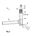
- FIG. 2 is a wiper bearing 14 of a windshield wiper device 10 according to the invention shown in detail in a perspective side view.
- the wiper shaft 22 is mounted in a substantially tubular bearing housing 24 of the wiper bearing 14. It has a first end 26 on which it is rotatably connected to a, not shown here for reasons of clarity, wiper arm.
- This first end 26 consists of a tapered portion, which opens in a thread to the end of the wiper shaft 22.
- the drive crank 32 is arranged in the region of the wiper shaft 22, which faces away from the first end 26 of the wiper shaft 22 along the longitudinal extent. This drive crank 32 is in turn connected to the push rod 20 (FIG. FIG. 1 ) hingedly connected.
- the wiper shaft on a projection 34 which is formed as a disc and is fixed axially on the wiper shaft 22.
- the lug 34 may also be integrally formed with the wiper shaft 22 or formed by the drive crank 32 itself, if these - as in FIG. 1 shown - in the region of the first end 26 of the wiper shaft 22 is arranged.
- the projection 34 is formed as a radially and axially movable disc whose axial mobility is limited by the drive crank 32. In principle, the approach 34 but also from one at least partially annular recess or an opening in which a snap ring or a pin or bolt or any other retaining element is inserted.
- the wiper shaft 22 protrudes from an end face of the bearing housing 24, which faces the first end 26, out. Between the projection 34 and the end face of the bearing housing 24, a bridge element is attached as an element 40. To support the element 40, a metal or plastic disk can also be arranged as a thrust washer on the end face of the bearing housing.
- the drive crank 32 On the front side of the bearing housing 24, which faces away from the bridge element 40, the drive crank 32 is non-rotatably connected to the wiper shaft 22.
- the drive crank 32 is in this case directly on the end face of the bearing housing 24, so that the wiper shaft is axially fixed by the projection 34 and the drive crank 32.
- Between the bridge element 40 facing away from the end face of the bearing housing 24 and the drive crank 32 may also be provided one or more thrust washers.
- the drive crank 32 arranged in the region of the first end 26 of the wiper shaft 22, it can be provided for axial fixation at the end remote from the first end 26 of the wiper shaft 22, a special fixing element.
- the drive crank 32 can then replace the projection 34.
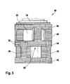
- the bridge member 40 is shown in detail with a portion of the wiper shaft 22 and the projection 34 in a side view.
- the bridge element 40 essentially comprises three planes (42, 44, 46), which are essentially annular in shape and nestle around the wiper shaft 22 in the assembled state.
- connecting webs 48 are arranged, which extend perpendicularly from the bottom-side plane 42, parallel to the wiper shaft 22, and are of substantially parallelepiped shape.
- These connecting webs 48 carry the median plane 44. Offset from the connecting webs, which extend from the bottom-side plane 42, further connecting webs 48 are arranged on the median plane 44.
- each plane 42, 44, 46 is connected by connecting webs 48 to the respective adjacent plane 42, 44, 46.
- For each connecting web 48 at least one predetermined breaking point 52 in the adjacent plane 44, provided that it does not form the bottom-side plane 42 or the ceiling plane 46, so no marginal level 42, 46 forms.
- predetermined breaking points 52 are arranged on all middle planes 44, as connecting webs 48 emanating from it.
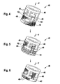
- the bridge element 40 during an impact force F, as this can occur in a colliding with the free end 26 of the wiper shaft 22 pedestrian.
- the reference numbers are the same here as in FIG. 3 selected.
- the bridge element 40 has four connecting webs 48 between in each case two adjacent planes 42, 44, 46.
- eight predetermined breaking points 52 are provided in the median plane 44, which are each between two of the eight connecting webs 48.
- the two marginal levels 42, 46 have no predetermined breaking points 52. In this way, the upper ceiling level 46, together with the connecting webs 48 extending from it, can move in the direction of the floor level 42 when the predetermined breaking points 52 break.
- the connecting webs 48 which are connected to the ceiling plane 46, slide then between the connecting webs 48, which are connected to the ground plane 42, down, whereby the overall height of the bridge element 40 is substantially reduced. Since the ceiling plane 46 forms the abutment surface for the lug 34, which is axially fixedly connected to the wiper shaft 22, the first end 26 of the wiper shaft 22 can slide down in this way, or in other words, by an impulse pushes the ceiling plane 46 with the connecting webs 48 on the median plane 44, whereby the predetermined breaking points 52 break.
- the ceiling plane 46 slides with the extending from her connecting webs 48 downwards in such a way that the connecting webs 48 which extend from the bottom-side plane 42, crown-like with the connecting webs 48 which extend from the ceiling plane 46 mesh.
- a force F greater than a predetermined force
- FIG. 7 is the wiper bearing 14 off FIG. 2 after a force F shown.
- the bridge element 40 is compressed by the retraction of the first end 26 of the wiper shaft 22 with the projection 34.
- the middle plane 44 is destroyed.
- the wiper shaft 22 has slid downwards within the bearing housing 24, so that a gap L results between the end face of the bearing housing 24 facing away from the first end 26 of the wiper shaft 22 and the drive crank 32.
- the wiper shaft 22 has thus slid down within the bearing housing 24.
- FIG. 8 a variation of the invention is shown.
- the bridge element 40 is formed integrally with the bearing housing 24.
- the end face of the wiper bearing 24 itself forms the bottom plane 42 of the bridge element 40.
- the bridge element 40 is made in one piece from plastic. Of course, a production of metal or ceramic is possible and is determined according to the required forces and Kraftverlaufsprofilen by the expert.
- the bearing housing 24 may also be formed of plastic. Just as in the bridge member 40 and the bearing housing 24 is a training as an injection molded part - even in a multi-component Injection molding - possible. A corresponding die-casting process is also suitable, in particular in the case of a construction made of metal.
- securing means for example a cam or a pin with a respective corresponding recess in the bearing housing 24 or in the bridge element 40 can also be provided. These must be arranged so that the crown-like displacement of the top surface 46 with the connecting webs 48 is not hindered by the force F.
Description
Die Erfindung betrifft eine Scheibenwischvorrichtung, insbesondere für ein Kraftfahrzeug, nach Gattung des unabhängigen Anspruchs.The invention relates to a windshield wiper device, in particular for a motor vehicle, according to the preamble of the independent claim.
Es sind schon zahlreiche Scheibenwischvorrichtungen, beispielsweise aus der
Aus der
Die erfindungsgemäße Scheibenwischvorrichtung mit den Merkmalen des Hauptanspruchs hat den Vorteil, dass das Element als Brückenelement ausgebildet ist. Auf diese Weise kann die Kraft, die benötigt wird, um das Zurückweichen der Wischerwelle zu ermöglichen, genau dosiert werden und bleibt über die Lebensdauer der Scheibenwischvorrichtung konstant. Darüber hinaus ist eine derartige Ausbildung einfach und kostengünstig herzustellen.The windshield wiper device according to the invention with the features of the main claim has the advantage that the element is designed as a bridge element. In this way, the force needed to allow the wiper shaft to recede can be accurately metered and remains constant throughout the life of the windshield wiper device. Moreover, such a design is simple and inexpensive to manufacture.
Durch die in den Unteransprüchen aufgeführten Maßnahmen ergeben sich vorteilhafte Weiterbildungen und Verbesserungen der im Hauptanspruch angegebenen Merkmale.The measures listed in the dependent claims, advantageous refinements and improvements of the main claim features.
Die Wischerwelle weist einen Ansatz auf und das Brückenelement first zwischen dem Lagergehäuse und dem Ansatz angeordnete, um eine stabile axiale Fixierung im Normalbetrieb zu ermöglichen.The wiper shaft has a shoulder and the bridge element first between the bearing housing and the approach arranged to allow stable axial fixation in normal operation.
In einer einfachen Ausführung ist der Ansatz im Wesentlichen scheibenförmig ausgebildet und umgreift die Wischerwelle.In a simple embodiment, the approach is essentially disc-shaped and surrounds the wiper shaft.
Vorteilhafter Weise kann ein Bauteil eingespart werden, wenn der Ansatz einstückig mit der der Wischerwelle ausgebildet ist.Advantageously, a component can be saved if the approach is formed integrally with that of the wiper shaft.
Das Brückenelement weist auch mindestens drei zur Wischerwelle koaxiale Ebenen auf, die durch Verbindungsstege verbunden sind. Hierbei ist es weiterhin vorteilhaft, wenn die Verbindungsstege schräg zur Wischerwelle verlaufen.The bridge element also has at least three planes coaxial with the wiper shaft, which are connected by connecting webs. Here, it is also advantageous if the connecting webs extend obliquely to the wiper shaft.
Besonders vorteilhaft ist es, wenn die Verbindungsstege parallel zur Wischerwelle angeordnet sind. Hierbei ist es weiterhin von Vorteil, wenn die Verbindungsstege sich bei einer Projektion auf eine zur Wischerwelle parallele Ebene nicht überlappen, um eine einfache und kostengünstige Möglichkeit der Fertigung des Brückenelementes zu ermöglichen.It when the connecting webs are arranged parallel to the wiper shaft is particularly advantageous. In this case, it is furthermore advantageous if the connecting webs do not overlap in a projection onto a plane parallel to the wiper shaft in order to enable a simple and cost-effective possibility of producing the bridge element.
In einer besonders wirkungsvollen Ausbildung der Scheibenwischvorrichtung weist das Brückenelement eine Sollbruchstelle auf.In a particularly effective embodiment of the windshield wiper device, the bridge element has a predetermined breaking point.
Hierbei ist es von Vorteil, wenn die Sollbruchstelle in mindestens einer Ebene, insbesondere in einer der Mittelebenen, angeordnet ist.It is advantageous if the predetermined breaking point is arranged in at least one plane, in particular in one of the center planes.
Eine besonders wirkungsvolle Variante ist dadurch gegeben, dass jede Ebene durch mindestens drei, insbesondere vier, Verbindungsstege mit der jeweils angrenzenden Ebene verbunden ist und für jeden Verbindungssteg mindestens eine Sollbruchstelle in der angrenzenden, nicht randständigen Ebene vorgesehen ist, um ein leichtes Zurückweichen der Wischerwelle beim Aufprall eines Fußgängers zu ermöglichen.A particularly effective variant is given by the fact that each level is connected by at least three, in particular four, connecting webs with the respective adjacent level and for each connecting web at least one predetermined breaking point in the adjacent, not marginal level is provided to a slight retreat of the wiper shaft To allow impact of a pedestrian.
In einer besonders einfachen Ausführungsform ist die Wischerwelle durch eine Antriebskurbel antreibbar, die einstückig mit dem Ansatz ausgebildet ist oder selbst als Ansatz dient.In a particularly simple embodiment, the wiper shaft is drivable by a drive crank, which is formed integrally with the approach or even serves as an approach.
Vorteilhafterweise ist das Brückenelement korrosionsgeschützt ausgeführt, insbesondere aus Kunststoff ausgebildet. Eine lange Lebensdauer und eine sichere Funktion wird dadurch erzielt, dass das Lagergehäuse, die Wischerwelle oder der Ansatz Sicherungsmittel aufweisen, die ein Verdrehen oder Verschieben des Brückenelementes verhindern.Advantageously, the bridge element is executed protected against corrosion, in particular made of plastic. A long life and a safe function is achieved in that the bearing housing, the wiper shaft or the approach have securing means which prevent twisting or displacement of the bridge element.
Besonders einfach und kostengünstig kann das Brückenelement einstückig mit dem Lagergehäuse ausgebildet sein.Particularly simple and inexpensive, the bridge element may be integrally formed with the bearing housing.
Verschiedene Ausführungsbeispiele der Erfindung sind in den Zeichnungen dargestellt und in der nachfolgenden Beschreibung näher erläutert. Es zeigen:
- Figur 1
- eine erfindungsgemäße Scheibenwischvorrichtung in einer perspektivischen Darstellung,
- Figur 2
- das Wischerlager einer erfindungsgemäßen Scheibenwischvorrichtung in einer Seitenansicht,
- Figur 3
- ein Brückenelement einer erfindungsgemäßen Scheibenwischvorrichtung in einer Seitenansicht,
- Figuren 4, 5 und 6
- ein Brückenelement einer erfindungsgemäßen Scheibenwischvorrich-tung während eines Aufpralls,
- Figur 7
- das Wischerlager aus
Figur 2 nach einem Aufprall und - Figur 8
- ein Wischerlager einer erfindungsgemäßen Scheibenwischvorrichtung in einer Variation.
- FIG. 1
- a windshield wiper device according to the invention in a perspective view,
- FIG. 2
- the wiper bearing of a windscreen wiper device according to the invention in a side view,
- FIG. 3
- a bridge element of a windshield wiper device according to the invention in a side view,
- FIGS. 4, 5 and 6
- a bridge element of a windscreen wiper device according to the invention during an impact,
- FIG. 7
- the wiper bearing off
FIG. 2 after a crash and - FIG. 8
- a wiper bearing of a windshield wiper device according to the invention in a variation.
In
Das Wischerlager 14 weist darüber hinaus noch ein Befestigungsauge 15 auf, welches auf der dem Trägerrohr abgewandten Seite des Wischerlagers angeordnet ist. In dem Befestigungsauge 15 sitzt eine Gummimuffe 17 zur Schwingungsdämpfung des Systems.The wiper bearing 14 also has a fastening eye 15, which is arranged on the side facing away from the carrier tube of the wiper bearing. In the mounting eye 15 sits a rubber sleeve 17 for vibration damping of the system.
In
Die Wischerwelle 22 ragt aus einer Stirnseite des Lagergehäuses 24, die dem ersten Ende 26 zugewandt ist, heraus. Zwischen dem Ansatz 34 und der Stirnseite des Lagergehäuses 24 ist ein Brückenelement als Element 40 aufgesteckt. Zur Abstützung des Elementes 40 kann auf der Stirnseite des Lagergehäuses auch noch eine Metall- oder Kunststoffscheibe als Anlaufscheibe angeordnet sein.The
Auf der Stirnseite des Lagergehäuses 24, die dem Brückenelement 40 abgewandt ist, ist die Antriebskurbel 32 drehfest mit der Wischerwelle 22 verbunden. Die Antriebskurbel 32 liegt hierbei direkt auf der Stirnseite des Lagergehäuses 24 an, sodass die Wischerwelle durch den Ansatz 34 und die Antriebskurbel 32 axial fixiert ist. Zwischen der dem Brückenelement 40 abgewandten Stirnseite des Lagergehäuses 24 und der Antriebskurbel 32 können auch noch eine oder mehrere Anlaufscheiben vorgesehen sein.On the front side of the bearing
Ist - wie in
In
In der Mittelebene 44 ergibt sich damit zwischen jeweils zwei von der bodenseitigen Ebene 42 ausgehenden Verbindungsstegen 48 ein Brückenbereich 50. Von diesem aus erstreckt sich ein Verbindungssteg 48 von der Mittelebene 44 zur Deckebene 46 hin. In den Bereichen der Mittelebene 44, auf denen diese nicht durch die Verbindungsstege 48 abgestützt ist und sich auch keine Verbindungsstege 48 zum Tragen der Deckfläche 46 befinden, sind Sollbruchstellen 52 angeordnet, die beispielsweise durch eine Verjüngung, bzw. Verringerung des Widerstandsquerschnitts der Mittelebene 44, beispielsweise durch einen Einschnitt, gebildet sind.In the
Allgemeiner formuliert ist somit jede Ebene 42, 44, 46 durch Verbindungsstege 48 mit der jeweils angrenzenden Ebene 42, 44, 46 verbunden. Für jeden Verbindungssteg 48 ist mindestens eine Sollbruchstelle 52 in der angrenzenden Ebene 44, vorgesehen, sofern diese nicht die bodenseitige Ebene 42 oder die Deckebene 46 bildet, also keine randständige Ebene 42, 46 bildet. Damit sind auf allen Mittelebenen 44 genau so viele Sollbruchstellen 52 angeordnet, wie Verbindungsstege 48 von ihr ausgehen.More generally, each
Auf der Deckebene 46 kommt der Ansatz 34 zu liegen, sodass die Wischerwelle 22 axial gegen ein Verschieben nach unten abgestützt ist.On the
In den
Nach einem derartigen Aufprall müssen auf diese Weise nur die Brückenelemente 40 der Scheibenwischvorrichtung 10 ausgetauscht werden.After such an impact only the
In
In
Das Brückenelement 40 ist einstückig aus Kunststoff hergestellt. Natürlich ist auch eine Herstellung aus Metall oder Keramik möglich und wird entsprechend den erforderlichen Kräften und Kraftverlaufsprofilen vom Fachmann festgelegt. Das Lagergehäuse 24 kann ebenfalls aus Kunststoff ausgebildet sein. Genauso wie beim Brückenelement 40 ist auch beim Lagergehäuse 24 eine Ausbildung als Spritzgussteil - auch in einem mehrkomponentigen Spritzgußverfahren - möglich. Auch ein entsprechendes Druckgussverfahren kommt, insbesondere bei einer Ausbildung aus Metall, in Betracht.The
Um ein Verdrehen des Brückenelementes 40 während des Betriebs zu verhindern, können auch Sicherungsmittel, beispielsweise eine Nocke oder ein Stift mit einer jeweils korrespondierenden Aussparung im Lagergehäuse 24 bzw. im Brückenelement 40 vorgesehen sein. Diese müssen so angeordnet sein, dass das kronenartige Verschieben der Deckfläche 46 mit den Verbindungsstegen 48 durch die Krafteinwirkung F nicht behindert ist.In order to prevent twisting of the
Claims (13)
- Windscreen wiper device (10), in particular for a motor vehicle, with at least one wiper bearing (14), which comprises a bearing housing (24), a wiper shaft (22) which is mounted in the bearing housing (24) and is capable of bearing a wiper arm at a first end (26), and an element (40) which supports the wiper shaft (22) axially, wherein the element (40) is designed as a bridge element, characterized in that the wiper shaft (22) has a collar (34), and the bridge element (40) is arranged between the bearing housing (24) and the collar (34), wherein the bridge element (40) has at least three planes (42, 44, 46) which are coaxial to the wiper shaft and are connected by connecting webs (48).
- Windscreen wiper device (10) according to Claim 1, characterized in that the collar (34) is of substantially disc-shaped design and substantially engages around the wiper shaft.
- Windscreen wiper device (10) according to Claim 1 or 2, characterized in that the collar (34) is formed integrally with the wiper shaft (22).
- Windscreen wiper device (10) according to Claim 1, characterized in that the connecting webs (48) run obliquely to the wiper shaft (22).
- Windscreen wiper device (10) according to Claim 1, characterized in that the connecting webs (48) are arranged parallel to the wiper shaft (22).
- Windscreen wiper device (10) according to Claim 5, characterized in that the connecting webs (48) do not overlap in a projection onto a plane parallel to the wiper shaft.
- Windscreen wiper device (10) according to one of the preceding claims, characterized in that the bridge element (40) has at least one predetermined breaking point (52).
- Windscreen wiper device (10) according to Claim 7, characterized in that the at least one predetermined breaking point (52) is provided in at least one plane (42, 44, 46) , in particular in one of the centre planes (44).
- Windscreen wiper device (10) according to one of Claims 1 and 4 to 8, characterized in that each plane (42, 44, 46) is connected to the respectively adjacent plane (42, 44, 46) by at least three, in particular four, connecting webs (48), and, for each connecting web (48), at least one predetermined breaking point (52) is provided in the adjacent, non-marginal plane (42, 46).
- Windscreen wiper device (10) according to one of the preceding claims, characterized in that the wiper shaft (22) is drivable by a driving crank (32) which is formed integrally with the collar (34) or itself serves as the collar (34).
- Windscreen wiper device (10) according to one of the preceding claims, characterized in that the bridge element (40) is corrosion-protected, in particular is formed from plastic.
- Windscreen wiper device (10) according to one of the preceding claims, characterized in that the bearing housing (24), the wiper shaft (22) or the collar (34) has securing means (37) against rotation and/or displacement of the bridge element (40).
- Windscreen wiper device (10) according to one of the preceding claims, characterized in that the bridge element (40) is formed integrally with the bearing housing.
Priority Applications (1)
| Application Number | Priority Date | Filing Date | Title |
|---|---|---|---|
| PL06778082T PL1926641T3 (en) | 2005-09-09 | 2006-07-31 | Windscreen wiper device, in particular for a motor vehicle |
Applications Claiming Priority (2)
| Application Number | Priority Date | Filing Date | Title |
|---|---|---|---|
| DE102005042847A DE102005042847A1 (en) | 2005-09-09 | 2005-09-09 | Windscreen wiper device, in particular for a motor vehicle |
| PCT/EP2006/064857 WO2007028678A1 (en) | 2005-09-09 | 2006-07-31 | Windscreen wiper device, in particular for a motor vehicle |
Publications (2)
| Publication Number | Publication Date |
|---|---|
| EP1926641A1 EP1926641A1 (en) | 2008-06-04 |
| EP1926641B1 true EP1926641B1 (en) | 2012-09-12 |
Family
ID=37067398
Family Applications (1)
| Application Number | Title | Priority Date | Filing Date |
|---|---|---|---|
| EP06778082A Expired - Fee Related EP1926641B1 (en) | 2005-09-09 | 2006-07-31 | Windscreen wiper device, in particular for a motor vehicle |
Country Status (6)
| Country | Link |
|---|---|
| US (1) | US8196253B2 (en) |
| EP (1) | EP1926641B1 (en) |
| CN (1) | CN101258062A (en) |
| DE (1) | DE102005042847A1 (en) |
| PL (1) | PL1926641T3 (en) |
| WO (1) | WO2007028678A1 (en) |
Families Citing this family (21)
| Publication number | Priority date | Publication date | Assignee | Title |
|---|---|---|---|---|
| DE102006027345B4 (en) * | 2006-06-13 | 2018-03-22 | Valeo Wischersysteme Gmbh | Wiper system for vehicle windows |
| US8516647B2 (en) * | 2009-10-14 | 2013-08-27 | Trico Products Corporation | Collapsible pivot body for a windshield wiper system |
| DE102009046203A1 (en) * | 2009-10-30 | 2011-05-12 | Robert Bosch Gmbh | Drive device in a windshield wiper device of a vehicle |
| DE102009054830A1 (en) * | 2009-12-17 | 2011-06-22 | Robert Bosch GmbH, 70469 | Windshield wiper device |
| US9457768B2 (en) | 2011-04-21 | 2016-10-04 | Pylon Manufacturing Corp. | Vortex damping wiper blade |
| CA2843527C (en) | 2011-07-28 | 2018-11-27 | Pylon Manufacturing Corp. | Windshield wiper adapter, connector and assembly |
| US9108595B2 (en) | 2011-07-29 | 2015-08-18 | Pylon Manufacturing Corporation | Windshield wiper connector |
| US20130219649A1 (en) | 2012-02-24 | 2013-08-29 | Pylon Manufacturing Corp. | Wiper blade |
| CA2865292C (en) | 2012-02-24 | 2018-03-13 | Pylon Manufacturing Corp. | Wiper blade |
| US10723322B2 (en) | 2012-02-24 | 2020-07-28 | Pylon Manufacturing Corp. | Wiper blade with cover |
| DE102012211072A1 (en) * | 2012-06-27 | 2014-01-02 | Robert Bosch Gmbh | Windscreen wiper device for cleaning e.g. windscreen of car, has decoupling system comprising attaching part for receiving fixing pin, which is held in axial direction by snap connection in attaching part |
| US10829092B2 (en) | 2012-09-24 | 2020-11-10 | Pylon Manufacturing Corp. | Wiper blade with modular mounting base |
| US10166951B2 (en) | 2013-03-15 | 2019-01-01 | Pylon Manufacturing Corp. | Windshield wiper connector |
| FR3016584B1 (en) * | 2014-01-21 | 2017-08-11 | Peugeot Citroen Automobiles Sa | WIPER FIXING DEVICE |
| US9505380B2 (en) | 2014-03-07 | 2016-11-29 | Pylon Manufacturing Corp. | Windshield wiper connector and assembly |
| US10363905B2 (en) | 2015-10-26 | 2019-07-30 | Pylon Manufacturing Corp. | Wiper blade |
| US10766462B2 (en) | 2016-05-19 | 2020-09-08 | Pylon Manufacturing Corporation | Windshield wiper connector |
| US11040705B2 (en) | 2016-05-19 | 2021-06-22 | Pylon Manufacturing Corp. | Windshield wiper connector |
| US10513246B2 (en) | 2016-05-19 | 2019-12-24 | Pylon Manufacturing Corp. | Windshield wiper connector |
| EP3458315B1 (en) | 2016-05-19 | 2021-09-08 | Pylon Manufacturing Corp. | Windshield wiper blade |
| AU2017267978A1 (en) | 2016-05-19 | 2018-11-22 | Pylon Manufacturing Corp. | Windshield wiper connector |
Citations (1)
| Publication number | Priority date | Publication date | Assignee | Title |
|---|---|---|---|---|
| EP1809520B1 (en) * | 2004-11-04 | 2009-08-12 | Renault s.a.s. | Windscreen wiper device for vehicle |
Family Cites Families (9)
| Publication number | Priority date | Publication date | Assignee | Title |
|---|---|---|---|---|
| JP4024316B2 (en) * | 1998-01-29 | 2007-12-19 | ローベルト ボツシユ ゲゼルシヤフト ミツト ベシユレンクテル ハフツング | Wiper device |
| US6317918B1 (en) * | 1998-04-24 | 2001-11-20 | Honda Giken Kogyo Kabushiki Kaisha | Windshield wiper device for vehicle |
| DE19909970A1 (en) * | 1999-03-06 | 2000-09-07 | Bosch Gmbh Robert | Device for fastening a component on a drive shaft of a wiper system |
| US6568023B2 (en) | 2000-12-14 | 2003-05-27 | Ford Global Technologies, L.L.C. | Wiper pivot |
| DE10242114A1 (en) | 2002-09-11 | 2004-03-25 | Robert Bosch Gmbh | Windscreen wiper device, in particular for a motor vehicle |
| DE10255775A1 (en) | 2002-11-29 | 2004-06-09 | Robert Bosch Gmbh | Windscreen wiper device, in particular for a motor vehicle |
| DE10255774B4 (en) * | 2002-11-29 | 2017-02-02 | Robert Bosch Gmbh | Windscreen wiper device, in particular for a motor vehicle |
| DE10305309B4 (en) | 2003-02-10 | 2014-10-30 | Robert Bosch Gmbh | Fastening device for a windshield wiper drive on a vehicle |
| DE10361744A1 (en) | 2003-12-29 | 2005-07-28 | Robert Bosch Gmbh | Windscreen wiper device, in particular for a motor vehicle |
-
2005
- 2005-09-09 DE DE102005042847A patent/DE102005042847A1/en not_active Ceased
-
2006
- 2006-07-31 CN CNA2006800328838A patent/CN101258062A/en active Pending
- 2006-07-31 WO PCT/EP2006/064857 patent/WO2007028678A1/en active Application Filing
- 2006-07-31 EP EP06778082A patent/EP1926641B1/en not_active Expired - Fee Related
- 2006-07-31 US US11/997,803 patent/US8196253B2/en not_active Expired - Fee Related
- 2006-07-31 PL PL06778082T patent/PL1926641T3/en unknown
Patent Citations (1)
| Publication number | Priority date | Publication date | Assignee | Title |
|---|---|---|---|---|
| EP1809520B1 (en) * | 2004-11-04 | 2009-08-12 | Renault s.a.s. | Windscreen wiper device for vehicle |
Also Published As
| Publication number | Publication date |
|---|---|
| US20080222828A1 (en) | 2008-09-18 |
| CN101258062A (en) | 2008-09-03 |
| EP1926641A1 (en) | 2008-06-04 |
| DE102005042847A1 (en) | 2007-03-15 |
| US8196253B2 (en) | 2012-06-12 |
| WO2007028678A1 (en) | 2007-03-15 |
| PL1926641T3 (en) | 2013-02-28 |
Similar Documents
| Publication | Publication Date | Title |
|---|---|---|
| EP1926641B1 (en) | Windscreen wiper device, in particular for a motor vehicle | |
| EP1263632B1 (en) | Wiper system | |
| EP1713668B1 (en) | Windscreen wiping device, particularly for a motor vehicle | |
| EP1718507B1 (en) | Windscreen wiper system for vehicles and fixing device for such a system | |
| EP2026998B1 (en) | Wiper system for vehicle windows | |
| EP1458596B1 (en) | Fixation of a wiper system | |
| WO2005082689A1 (en) | Windshield wiping device, especially for a motor vehicle | |
| EP3385143B1 (en) | Pivot device for a coupling in particular of a railway vehicle | |
| DE102010042374B4 (en) | wiper device | |
| DE102004005065A1 (en) | Windscreen wiper especially for a motor vehicle has two part wiper shaft having relative movement under an axial force to move into the vehicle | |
| EP1763460B1 (en) | Device for fastening a window wiping device to a motor vehicle | |
| EP2167354B1 (en) | Fastening arrangement | |
| EP1910139A1 (en) | Windscreen wiper device, in particular for a motor vehicle | |
| EP1651480B1 (en) | Fastening system | |
| EP1567396A1 (en) | Window-wiping device, particularly for a motor vehicle | |
| DE10343572A1 (en) | Flexible assembly for driving shaft of windshield wiper, has bushings displaced, along with shaft, in axial direction when shaft is subjected to collision, and clutch spring arranged coaxially to shaft | |
| DE10255774B4 (en) | Windscreen wiper device, in particular for a motor vehicle | |
| EP1368215A1 (en) | Wiper arm | |
| EP1716026B1 (en) | Windscreen wiper device | |
| DE102007009566B4 (en) | Gear drive unit with bearing bolt fixed to the housing | |
| DE102006004048B4 (en) | Fastening device for use in a wiper system for vehicles and wiper system | |
| DE19908888B4 (en) | Adjustable rearview mirror, in particular exterior mirrors for a motor vehicle | |
| WO2012059146A1 (en) | Force limiting device, belt retractor having a force limiting device, and method for switching over a force limiting device | |
| EP1723014A1 (en) | Windshield wiper device, particularly for a motor vehicle | |
| DE10145209B4 (en) | Headrest assembly for a motor vehicle |
Legal Events
| Date | Code | Title | Description |
|---|---|---|---|
| PUAI | Public reference made under article 153(3) epc to a published international application that has entered the european phase |
Free format text: ORIGINAL CODE: 0009012 |
|
| 17P | Request for examination filed |
Effective date: 20080409 |
|
| AK | Designated contracting states |
Kind code of ref document: A1 Designated state(s): CZ FR GB IT PL |
|
| RBV | Designated contracting states (corrected) |
Designated state(s): CZ FR GB IT PL |
|
| RBV | Designated contracting states (corrected) |
Designated state(s): CZ DE FR GB IT PL |
|
| RBV | Designated contracting states (corrected) |
Designated state(s): CZ DE FR GB IT PL |
|
| 17Q | First examination report despatched |
Effective date: 20090518 |
|
| GRAP | Despatch of communication of intention to grant a patent |
Free format text: ORIGINAL CODE: EPIDOSNIGR1 |
|
| DAX | Request for extension of the european patent (deleted) | ||
| GRAS | Grant fee paid |
Free format text: ORIGINAL CODE: EPIDOSNIGR3 |
|
| GRAA | (expected) grant |
Free format text: ORIGINAL CODE: 0009210 |
|
| AK | Designated contracting states |
Kind code of ref document: B1 Designated state(s): CZ DE FR GB IT PL |
|
| REG | Reference to a national code |
Ref country code: GB Ref legal event code: FG4D Free format text: NOT ENGLISH |
|
| REG | Reference to a national code |
Ref country code: DE Ref legal event code: R096 Ref document number: 502006011984 Country of ref document: DE Effective date: 20121108 |
|
| REG | Reference to a national code |
Ref country code: PL Ref legal event code: T3 |
|
| PLBE | No opposition filed within time limit |
Free format text: ORIGINAL CODE: 0009261 |
|
| STAA | Information on the status of an ep patent application or granted ep patent |
Free format text: STATUS: NO OPPOSITION FILED WITHIN TIME LIMIT |
|
| 26N | No opposition filed |
Effective date: 20130613 |
|
| REG | Reference to a national code |
Ref country code: DE Ref legal event code: R097 Ref document number: 502006011984 Country of ref document: DE Effective date: 20130613 |
|
| REG | Reference to a national code |
Ref country code: FR Ref legal event code: PLFP Year of fee payment: 10 |
|
| PGFP | Annual fee paid to national office [announced via postgrant information from national office to epo] |
Ref country code: GB Payment date: 20150724 Year of fee payment: 10 |
|
| PGFP | Annual fee paid to national office [announced via postgrant information from national office to epo] |
Ref country code: FR Payment date: 20150730 Year of fee payment: 10 |
|
| PGFP | Annual fee paid to national office [announced via postgrant information from national office to epo] |
Ref country code: IT Payment date: 20150728 Year of fee payment: 10 |
|
| PGFP | Annual fee paid to national office [announced via postgrant information from national office to epo] |
Ref country code: PL Payment date: 20160720 Year of fee payment: 11 Ref country code: CZ Payment date: 20160721 Year of fee payment: 11 |
|
| GBPC | Gb: european patent ceased through non-payment of renewal fee |
Effective date: 20160731 |
|
| PG25 | Lapsed in a contracting state [announced via postgrant information from national office to epo] |
Ref country code: FR Free format text: LAPSE BECAUSE OF NON-PAYMENT OF DUE FEES Effective date: 20160801 |
|
| REG | Reference to a national code |
Ref country code: FR Ref legal event code: ST Effective date: 20170331 |
|
| PG25 | Lapsed in a contracting state [announced via postgrant information from national office to epo] |
Ref country code: GB Free format text: LAPSE BECAUSE OF NON-PAYMENT OF DUE FEES Effective date: 20160731 |
|
| PG25 | Lapsed in a contracting state [announced via postgrant information from national office to epo] |
Ref country code: IT Free format text: LAPSE BECAUSE OF NON-PAYMENT OF DUE FEES Effective date: 20160731 |
|
| PGFP | Annual fee paid to national office [announced via postgrant information from national office to epo] |
Ref country code: DE Payment date: 20170927 Year of fee payment: 12 |
|
| PG25 | Lapsed in a contracting state [announced via postgrant information from national office to epo] |
Ref country code: CZ Free format text: LAPSE BECAUSE OF NON-PAYMENT OF DUE FEES Effective date: 20170731 |
|
| PG25 | Lapsed in a contracting state [announced via postgrant information from national office to epo] |
Ref country code: PL Free format text: LAPSE BECAUSE OF NON-PAYMENT OF DUE FEES Effective date: 20170731 |
|
| REG | Reference to a national code |
Ref country code: DE Ref legal event code: R119 Ref document number: 502006011984 Country of ref document: DE |
|
| PG25 | Lapsed in a contracting state [announced via postgrant information from national office to epo] |
Ref country code: DE Free format text: LAPSE BECAUSE OF NON-PAYMENT OF DUE FEES Effective date: 20190201 |