EP1926342A2 - Optisches Schaltsystem - Google Patents
Optisches Schaltsystem Download PDFInfo
- Publication number
- EP1926342A2 EP1926342A2 EP08075024A EP08075024A EP1926342A2 EP 1926342 A2 EP1926342 A2 EP 1926342A2 EP 08075024 A EP08075024 A EP 08075024A EP 08075024 A EP08075024 A EP 08075024A EP 1926342 A2 EP1926342 A2 EP 1926342A2
- Authority
- EP
- European Patent Office
- Prior art keywords
- working
- preparatory
- port
- path
- optical
- Prior art date
- Legal status (The legal status is an assumption and is not a legal conclusion. Google has not performed a legal analysis and makes no representation as to the accuracy of the status listed.)
- Withdrawn
Links
Images


Classifications
-
- H—ELECTRICITY
- H04—ELECTRIC COMMUNICATION TECHNIQUE
- H04J—MULTIPLEX COMMUNICATION
- H04J14/00—Optical multiplex systems
- H04J14/02—Wavelength-division multiplex systems
- H04J14/0287—Protection in WDM systems
- H04J14/0297—Optical equipment protection
-
- H—ELECTRICITY
- H04—ELECTRIC COMMUNICATION TECHNIQUE
- H04J—MULTIPLEX COMMUNICATION
- H04J14/00—Optical multiplex systems
- H04J14/02—Wavelength-division multiplex systems
- H04J14/0278—WDM optical network architectures
- H04J14/0283—WDM ring architectures
-
- H—ELECTRICITY
- H04—ELECTRIC COMMUNICATION TECHNIQUE
- H04J—MULTIPLEX COMMUNICATION
- H04J14/00—Optical multiplex systems
- H04J14/02—Wavelength-division multiplex systems
- H04J14/0287—Protection in WDM systems
- H04J14/0289—Optical multiplex section protection
- H04J14/0291—Shared protection at the optical multiplex section (1:1, n:m)
-
- H—ELECTRICITY
- H04—ELECTRIC COMMUNICATION TECHNIQUE
- H04J—MULTIPLEX COMMUNICATION
- H04J14/00—Optical multiplex systems
- H04J14/02—Wavelength-division multiplex systems
- H04J14/0287—Protection in WDM systems
- H04J14/0293—Optical channel protection
- H04J14/0294—Dedicated protection at the optical channel (1+1)
-
- H—ELECTRICITY
- H04—ELECTRIC COMMUNICATION TECHNIQUE
- H04Q—SELECTING
- H04Q11/00—Selecting arrangements for multiplex systems
- H04Q11/0001—Selecting arrangements for multiplex systems using optical switching
- H04Q11/0005—Switch and router aspects
-
- H—ELECTRICITY
- H04—ELECTRIC COMMUNICATION TECHNIQUE
- H04Q—SELECTING
- H04Q11/00—Selecting arrangements for multiplex systems
- H04Q11/0001—Selecting arrangements for multiplex systems using optical switching
- H04Q11/0062—Network aspects
-
- H—ELECTRICITY
- H04—ELECTRIC COMMUNICATION TECHNIQUE
- H04Q—SELECTING
- H04Q11/00—Selecting arrangements for multiplex systems
- H04Q11/0001—Selecting arrangements for multiplex systems using optical switching
- H04Q11/0005—Switch and router aspects
- H04Q2011/0007—Construction
- H04Q2011/0024—Construction using space switching
-
- H—ELECTRICITY
- H04—ELECTRIC COMMUNICATION TECHNIQUE
- H04Q—SELECTING
- H04Q11/00—Selecting arrangements for multiplex systems
- H04Q11/0001—Selecting arrangements for multiplex systems using optical switching
- H04Q11/0005—Switch and router aspects
- H04Q2011/0037—Operation
- H04Q2011/0043—Fault tolerance
-
- H—ELECTRICITY
- H04—ELECTRIC COMMUNICATION TECHNIQUE
- H04Q—SELECTING
- H04Q11/00—Selecting arrangements for multiplex systems
- H04Q11/0001—Selecting arrangements for multiplex systems using optical switching
- H04Q11/0062—Network aspects
- H04Q2011/0079—Operation or maintenance aspects
- H04Q2011/0081—Fault tolerance; Redundancy; Recovery; Reconfigurability
-
- H—ELECTRICITY
- H04—ELECTRIC COMMUNICATION TECHNIQUE
- H04Q—SELECTING
- H04Q11/00—Selecting arrangements for multiplex systems
- H04Q11/0001—Selecting arrangements for multiplex systems using optical switching
- H04Q11/0062—Network aspects
- H04Q2011/009—Topology aspects
- H04Q2011/0092—Ring
Definitions
- the present invention relates to an optical switching system for carrying out path switching on a network that interconnects a plurality of nodes through a working path and a preparatory path using optical signals.
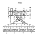
- Fig. 1 is a block diagram showing a partially redrawn conventionally studied optical switching system as disclosed under the title of " WDM four fiber ring experiment", B-10-230, page 739, Proceedings of the 1997 IEICE (the Institute of Electronics, Information and Communication Engineers of Japan ) General Conference; and Fig. 2 is a partially redrawn operational diagram illustrating a path switching operation in case of a fault described in this paper.
- reference numerals 111-114 each designate a node corresponding to the optical switching system as shown in Fig. 1 ; 115 designates an inside transmission path for transmitting optical signals in both directions used as the working path for interconnecting the nodes.
- the reference numeral 116 designates an outside path for transmitting optical signals in both directions used as the preparatory path for interconnecting the nodes.
- Reference numerals 117 each designate a 4x4 optical space switch in the node; 118 each designate a working terminal unit connected to the node; and 119 each designate a preparatory terminal unit.
- the transmission paths 115 and 116 that interconnect the nodes 111-114 are wavelength multiplexed, and are connected to the WRK in/out ports 106 and 107 and PRT in/out ports 108 and 109 of the optical switching system of Fig. 1 .
- Each acoustooptic filter 101 receiving a drive signal, isolates a particular wavelength signal to be connected to the optical space switch 102, and passes the remaining wavelength signals without change. Without the drive signal, all the wavelength optical signals pass through the acoustooptic filters 101. Thus, each acoustooptic filter 101 is used as a switch for switching whether to remove (denoted as "Drop" from now on) the wavelength from the transmission path or not by the drive signal.
- the isolated signals output from the acoustooptic filters 101 are connected to appropriate terminal units 105 via the optical space switches 102 to be received.
- the individual nodes are each connected to four terminal units 105, so that they are connected to East side and West side WRK in/out ports and PRT in/out ports.
- optical signals input to the optical switching system through the terminal units 105 are distributed to the appropriate recombining elements 103 at the output ports by the optical space switches 102, recombined with the optical signals of other wavelengths passing through the acoustooptic filters 101, and transmitted to adjacent nodes through the output ports as wavelength multiplex signals.
- the optical space switches 102 switch, if some fault takes place on the transmission path, the communications on the working system to the recombining elements 103 on the same or reverse direction preparatory path in accordance with the fault pattern, thereby saving the communications on the working system at the cost of the communications on the preparatory system.
- the network is constructed by providing the nodes of the transmission paths with the optical switching system with the foregoing functions and by connecting the transmission paths in a ring-like pattern.
- communications can be carried out using the working path and preparatory path as shown in Fig. 2(1) .
- the working terminal units 118 connected to the node 111 and to the node 113 are bidirectionally interconnected through the working path 115
- the terminal units 119 connected to the node 113 and to the node 114 are bidirectionally interconnected through the preparatory paths 116.
- the optical space switches 117 of the nodes 111 and 113 that carry out transmission and reception are switched to the preparatory paths of the same direction as shown in Fig. 2(2) , so that the communication path used by the working terminal unit 118 is switched to the preparatory path passing through the same route, thereby detouring the signal flowing through the transmission path 115 to the transmission path 116, and preventing the transmission path from being disconnected.
- the optical space switches 117 of the nodes 111 and 113 switch the input/output ports for transmission and reception to the opposite preparatory path side as shown in Fig. 2(3) , thereby detouring the signals to the transmission path 116 passing through the network in the opposite direction, and preventing the working path from being disconnected.
- the communications carried out between the nodes 113 and 114 using the transmission path 116 in the faultless state are disconnected to prevent the disconnection of the working transmission path.
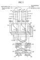
- Fig. 3 is a block diagram showing another partially redrawn conventionally studied optical switching system as disclosed under the title of " Node configuration on OADM ring system", B-10-85, page 384, Proceedings of the 1997 Society Conference of the Institute of Electronics, Information and Communication Engineers of Japan .
- reference numerals 121 each designate an optical switching system that receives currently working signals, and switches, in case of a transmission path fault, an optical signal path to an unimpaired transmission path; the reference numeral 122 designates a backup optical switching system used in place of one of the optical switching systems 121 when it is faulty; ⁇ (1)- ⁇ (n+1) each designate an optical signal with a different wavelength; reference numerals 127-128 each designate a terminal unit connected to the optical switching system 121 and 122 for transmitting and receiving the optical signals ⁇ (1)- ⁇ (n+1); 123 and 124 each designate a wavelength multiplexer for wavelength multiplexing the optical signals ⁇ (1)- ⁇ (n+1) with different wavelengths transmitted from the terminal units 127-128, and for sending them out to transmitting paths; 125 and 126 each designate a wavelength demultiplexer for demultiplexing the wavelength multiplex signals fed from receiving paths for respective wavelengths, and for inputting them to the optical switching systems corresponding to the optical signals ⁇ (1)-
- the reference numeral 24 designates a transmitting section installed in each optical switching system 121; 23 designates a receiving section installed in each optical switching system 121; 11 designates a working transmitted optical signal splitter provided for each transmitting section 24; and 22 designates a working received optical signal selector provided for each receiving section 23.
- the conventional example assumes to be applied to a ring network employing the bidirectional transmission paths that enable individual communications for respective wavelengths based on the wavelength multiplexing technique.
- Communication paths for optical signals of respective wavelengths comprise terminal units 127-128 and optical switching systems 121 and 122, and are connected to the transmission paths through the wavelength multiplexers 123 and 124 and the wavelength demultiplexers 125 and 126.
- the n intra-office interfaces 131 or 132 for outputting or inputting the optical signals to be transmitted or received correspond to n+1 wavelengths prepared in advance, and the n working channels have one preparatory channel, constituting a 1:n configuration.
- the intra-office interface associated with the fault is connected to the preparatory channel through the (n+1):n electric switch 129 or 130, thereby recovering the fault of the system.
- each of the optical switching systems 121 and 122 associated with respective wavelengths divides the transmitted signal into two with the working transmitted optical signal splitter 11, and sends them to the two transmitting paths.
- the working received optical signal selector 22 selects one of the optical signals fed from the two receiving paths. If a fault takes place on one of the two receiving paths, the working received optical signal selector 22 selects the remaining faultless receiving path to recover the fault of the transmission path.
- the conventional optical switching systems have the foregoing configurations.
- the first conventional example as shown in Figs. 1 and 2 disclosed in the B-10-230 paper employs, when the network is normal, both the working path and preparatory path separately for different communications, whereas in case of a fault it detours the currently working signals to the preparatory path using the 4x4 optical space switches 102 or 117 for the path switching.
- the 4x4 optical space switches 102 or 117 utilizing mechanical optical space switches can meet the foregoing characteristics with the reliability of practical level, and the mechanical switches with a latch function have an advantage of being able to eliminate the power required for holding the present state.
- These switches have a problem of increasing packaging dimensions because the function of a unit switch is limited to 1x2 or 2x2, which means that 16 unit switches are required to implement the 4x4 optical space switch 102 or 117 by combining the 2x2 unit switches.
- the conventional example has a problem of interrupting during the recovery job all the communications passing through the terminal units 105, 118 or 119 connected to the node because all the transmitted or received signals connected to the terminal units 105, 118 or 119 are connected to a single optical space switch 102 or 117.
- the conventional example as shown in Fig. 3 disclosed in the B-10-85 paper divides the output signals from the optical switching systems 121 and 122 to the two transmitting paths so that the two paths transmit the same signals. This presents a problem in that the working efficiency of the transmission paths is limited to 1/2 because the network always transmits the same signals through the two paths.
- an object of the present invention is to provide an optical switching system with high transmission path working efficiency without interrupting all the communications during the recovery job such as component replacement in case of a fault of an optical space switch by decreasing the number of the optical space switches, thereby reducing the packaging size with maintaining the characteristics and reliability of the optical space switches.
- the optical switching system comprises span switching means provided for each one of sets for switching between a working path and a preparatory path in the same section by switching or by passing through input and output optical signals from and to working input/output ports and from and to preparatory input/output ports; first ring switching means for supplying the span switching means of a first one of the sets with input and output signals associated with a preparatory add port of the first one of the sets, with a working add port of the first one of the sets, with a working drop port of the first one of the sets, and with a preparatory drop port of the first one of the sets by switching or passing through them; and second ring switching means for supplying the span switching means of a second one of the sets with input and output signals associated with a preparatory add port of the second one of the sets, with a working add port of the second one of the sets, with a working drop port of the second one of the sets, and with a preparatory drop port of the second one of the sets by switching or passing through them; and second
- the optical switching system is configured such that it comprises for each of the two sets the span switching means and the first and second ring switching means.
- the ring switching means can configure anther preparatory path in a reverse direction even if both the working path and preparatory path fall into a fault at the same time in a particular section of the ring network.
- the span switching means can detour the signals to the preparatory path in the same section when only the working path falls into a fault and the preparatory path is normal in the section. Providing the two switching modes can improve the reliability of the network.
- both the ring switching means and span switching means are composed of the optical space switches, the number of the optical switches required is small, offering an advantage of being able to reduce the packaging size. Moreover, because the total transmission capacity of both the working path and preparatory path can be utilized in the faultless state, the working efficiency of the transmission paths can be improved.
- Fig. 4 is a block diagram showing a configuration of an example 1 of an optical switching system not covered by the present invention.
- the reference numeral 1 designates an input port of a working system (denoted as "WRKin port” from now on) of the present embodiment 1 of the optical switching system; 2 designates an output port of the working system (denoted as “WRKout port”); 3 designates an input port of a preparatory system (denoted as "PRTin port” for now on); 4 designates an output port of the preparatory system (denoted as "PRTout port” from now on); 5 designates an add port of the working system (denoted as "Add(WRK) port” from now on) for inserting in or transmitting to a transmission path a signal through an optical switching system 18; 6 designates a drop port of the working system (denoted as "Drop(WRK) port” from now on) for discarding or receiving a signal from the transmission path through the optical switching system 18; 7 designates an add port of
- the reference numerals 18 and 26 each designate the optical switching system of the present example 1; 24 designates a transmitting section that transfers in faultless state the input optical signal to the Add(WRK) port 5 to the WRKout port 2, and the input optical signal to the Add(PRT) port 7 to the PRTout port 4, and that transfers, if a fault takes place on a transmitting side working path which is supplied with the optical signal from the WRKout port 2, the input optical signal to the Add(WRK) port 5 to both the WRKout port 2 and PRTout port 4; 23 designates a receiving section that supplies in the faultless state the input optical signal to the WRKin port 1 to the Drop(WRK) port 6, and the input optical signal to the PRTin port 3 to the Drop(PRT) port 8, and that supplies, if a fault takes place on a receiving side working path transmitting the optical signal to the WRKin port 1, the input signal to the PRTin port 3 to the Drop(WRK) port 6.
- the receiving optical switch 9 and preparatory receiving optical gate 10 are installed in the receiving section 23.
- the reference numeral 11 designates a transmitted optical signal splitter of the working system for dividing the optical signal input to the Add(WRK) port 5 into two, and for supplying one of them to the WRKout port 2; and 12 designates a preparatory transmitted optical signal selector for selecting one of the other output of the working transmitted optical signal splitter 11 and the optical signal input through the Add(PRT) port 7, and supplies the selected signal to the PRTout port 4.
- the working transmitted optical signal splitter 11 and preparatory transmitted optical signal selector 12 are both installed in the transmitting section 24.
- the reference numerals 13 and 19 each designate a working terminal unit for carrying out communications through the working paths when the transmission paths are normal; 14 and 20 each designate a preparatory terminal unit for carrying out the communications through the preparatory paths in the similar manner;
- the reference numeral 15 designates a working receiving path for connecting the WRKin port 1 of the optical switching system 18 with the WRKout port of the optical switching system 26;
- 16 designates a preparatory transmitting path for connecting the PRTout port 4 of the optical switching system 18 with the PRTin port of the optical switching system 26;
- 17 designates a preparatory receiving path for connecting the PRTin port 3 of the optical switching system 18 with the PRTout port of the optical switching system 26;
- 25 designates a working transmitting path for connecting the WRKout port 2 of the optical switching system 18 with the WRKin port of the optical switching system 26.
- optical switching systems 18 and 26 are interconnected through the working transmitting path 25 and working receiving path 15, and through the preparatory transmitting path 16 and preparatory receiving path 17.
- the optical switching systems 18 and 26 are connected with the working terminal units 13 and 19, and with the preparatory terminal units 14 and 20, respectively.
- the optical signal output from the working terminal unit 13 is supplied to the optical switching system 18 through the Add(WRK) port 5, and is transferred to the working terminal unit 19 through the working transmitted optical signal splitter 11, WRKout port 2, working transmitting path 25 and optical switching system 26.
- the working optical signal output from the working terminal unit 19 is supplied to the receiving optical switch 9 of the optical switching system 18 through the optical switching system 26, working receiving path 15 and WRKin port 1.
- the receiving optical switch 9 which is provided for switching the receiving path by bringing its internal optical transmission paths into a cross state if a fault takes place on the working receiving path 15, is in a through state in a faultless state so that the signal from the WRKin port 1 is transferred to the working terminal unit 13 through the Drop(WRK) port 6, thus establishing the bidirectional communication path between the working terminal units 13 and 19.
- the optical signal output from the preparatory terminal unit 20 is supplied to the PRTin port 3 through the optical switching system 26 and preparatory receiving path 17, and is connected to the preparatory receiving optical gate 10 through the receiving optical switch 9 in the through state, arriving at the preparatory terminal unit 14 through the preparatory receiving optical gate 10 in the transmissive state, thereby establishing the bidirectional communication path between the preparatory terminal units 14 and 20. Because the preparatory terminal units 14 and 20 can exchange signals different from those between the working terminal units 13 and 19, the total transmission capacity of both the working transmitting path 25 and receiving path 15 and of both the preparatory transmitting path 16 and receiving path 17 can be utilized in a faultless state.
- the communication is saved by switching the optical switching systems 18 and 26 to detour the working path communications to the preparatory path side.
- the optical switching system 26 divides the transmitted optical signal into two, and supplies them to both the working receiving path 15 and preparatory receiving path 17. In this case, the transmitted signal from the preparatory terminal unit 20 is discarded.
- the switching of the receiving optical switch 9 entails the path switching of the optical signal fed through the working receiving path 15 to the preparatory receiving optical gate 10 in the untransmissive state so that the optical signal is discarded by the gate function of the preparatory receiving optical gate 10.
- This can prevent the preparatory terminal unit 14, which receives the optical signal from the preparatory terminal unit 20 in a faultless state, from receiving the optical signal sent from the working terminal unit 19 during the recovery of the fault of the working receiving path 15.
- the gate function is essential to avoid erroneous connection in the case where the communication between the working terminal units 13 and 19 differ from that between the preparatory terminal units 14 and 20 in the faultless state.
- the preparatory transmitted optical signal selector 12 is brought in the cross state so that the transmitted signal from the working terminal unit 13 is divided by the working transmitted optical signal splitter 11 and delivered to both the WRKout port 2 and PRTout port 4 (bridging operation).
- the optical signal transmitted through the two paths, the working transmitting path 25 and the preparatory transmitting path 16, is received by the optical switching system 26 which selects the optical signal via the preparatory transmitting path 16 and connects it to the working terminal unit 19, thus recovering the communication between the working terminal units 13 and 19 suffering from the fault of the working transmitting path 25.
- the present example 1 can make full use of the total transmission capacity of both the working transmitting path 25 and working receiving path 15 and of both the preparatory transmitting path 16 and preparatory receiving path 17 in the faultless state.
- the communications of the preparatory system flowing through the preparatory transmitting path 16 and preparatory receiving path 17 are discarded, and the communications of the working system are detoured to the preparatory transmitting path 16 and preparatory receiving path 17. This offers an advantage of being able to save the communications of the working system.
- the number of the optical space switches the example 1 requires is small because the transmitting section 24 requires one 1x2 optical space switch (preparatory transmitted optical signal selector 12), the receiving section 23 requires one 2x2 optical space switch (receiving optical switch 9) and one optical gate switch (preparatory receiving optical gate 10). This offers an advantage of being able to reduce the packaging size.
- Fig. 5 is a block diagram showing a configuration of an example 2 of an optical switching system not covered by the present invention.
- the same components as those of the previous examples are designated by the same reference numerals, and the description thereof will be omitted.
- the reference numeral 21 designates a preparatory receiving optical switch for carrying out spatial path switching of the optical signal input from the PRTin port 3, and for supplying a first optical output to the Drop(PRT) port 8; and 22 designates a working received optical signal selector for selecting one of a second optical output of the preparatory receiving optical switch 21 and the optical signal supplied from the WRKin port 1, and for supplying the selected signal to the Drop(WRK) port 6.
- the reference numeral 23a designates a receiving section including the preparatory receiving optical switch 21 and the working received optical signal selector 22; and 18a designates an optical switching system of the present embodiment 2 comprising the transmitting section 24, receiving section 23a, WRKin port 1, WRKout port 2, PRTin port 3, PRTout port 4, Add(WRK) port 5, Drop(WRK) port 6, Add(PRT) port 7 and Drop(PRT) port 8.
- the optical switching system 18a of the present example 2 is identical to the optical switching system of the example 1 in that it can utilize in a faultless state the total transmission capacity of both the working transmitting path 25 and working receiving path 15 and of both the preparatory transmitting path 16 and preparatory receiving path 17, and in that it has the switching function inclusive of the function of breaking the optical signal in a fault switching to prevent the preparatory terminal unit 14 from being erroneously connected.
- the present example differs from the example 1 only in the configuration of the receiving section 23a.
- the receiving section 23a comprises two 2x1 optical space switches (the preparatory receiving optical switch 21 and working received optical signal selector 22).
- the preparatory receiving optical switch 21 and working received optical signal selector 22 are in the through connection state, establishing the connection between the WRKin port 1 and Drop(WRK) port 6, and the connection between the PRTin port 3 and Drop(PRT) port 8.
- a fault taking place on the working receiving path 15 will bring both the preparatory receiving optical switch 21 and working received optical signal selector 22 into the cross connection state, connecting the PRTin port 3 with the Drop(WRK) port 6.
- the working received optical signal selector 22 does not output the optical signal supplied from the WRKin port 1
- the Drop(PRT) port 8 connected to the preparatory terminal unit 14 does not output any optical signal. This can prevent the signal sent from the working terminal unit 19 from being connected to the preparatory terminal unit 14 when the fault takes place on the working receiving path 15, thereby preventing the erroneous connection.
- the present example 2 can make full use of the total transmission capacity of both the working transmitting path 25 and working receiving path 15 and of both the preparatory transmitting path 16 and preparatory receiving path 17 in the faultless state.
- the communications of the preparatory system flowing through the preparatory transmitting path 16 and preparatory receiving path 17 are discarded, and the communications of the working system are detoured to the preparatory transmitting path 16 or to the preparatory receiving path 17. This offers an advantage of being able to save the communications of the working system.
- the number of the optical space switches required is small because the transmitting section requires one 1 ⁇ 2 optical space switch (the preparatory transmitted optical signal selector 12), and the receiving section requires two 1 ⁇ 2 optical space switches (the preparatory receiving optical switch 21 and working received optical signal selector 22). This offers an advantage of being able to reduce the packaging size.
- each optical component transmits only one optical signal in the faultless state.
- the working transmitted optical signal splitter 11 transmits only the input signal fed from the Add(WRK) port 5
- the working received optical signal selector 22 transmits only the input signal fed from the WRKin port 1.
- Fig. 6 is a block diagram showing a configuration of an example 3 of the optical switching system not covered by the present invention.
- the reference numeral 31 designates a preparatory receiving optical splitter for dividing into two the optical signal supplied from the PRTin port 3;
- 32 designates a preparatory receiving optical gate installed between a first optical output of the preparatory receiving optical splitter 31 and the Drop(PRT) port 8 for switching between the optical transmissive state and untransmissive state.
- the working received optical signal selector 22 is mounted such that it selects one of a second optical output of the preparatory receiving optical splitter 31 and the optical signal supplied from the WRKin port 1, and outputs the selected signal to the Drop(WRK) port 6.
- the reference numeral 23b designates a receiving section comprising the preparatory receiving optical splitter 31, preparatory receiving optical gate 32 and working received optical signal selector 22; and 18b designates an optical switching system of the present embodiment 3 comprising the transmitting section 24, receiving section 23b, WRKin port 1, WRKout port 2, PRTin port 3, PRTout port 4, Add(WRK) port 5, Drop(WRK) port 6, Add(PRT) port 7 and Drop(PRT) port 8.
- the optical switching system 18b of the present example 3 is identical to the optical switching systems of the examples 1 and 2 in that it can utilize in the faultless state the total transmission capacity of both the working transmitting path 25 and working receiving path 15 and of both the preparatory transmitting path 16 and preparatory receiving path 17, and in that it has the switching function inclusive of the function of breaking the optical signal in a fault switching to prevent the preparatory terminal unit 14 from being erroneously connected.
- the present example differs from the examples 1 and 2 only in the configuration of the receiving section 23b.
- the optical signal supplied from the preparatory receiving path 17 to the PRTin port 3 is divided by the preparatory receiving optical splitter 31.
- the working received optical signal selector 22 selects one of the optical signals fed from the WRKin port 1 and PRTin port 3, and outputs the selected signal to the Drop(WRK) port 6.
- the working terminal unit 13 can receive the optical signal either from the working receiving path 15 or from the preparatory receiving path 17.
- the Drop(PRT) port 8 can either be connected to the optical signal input to the PRTin port 3, or be disconnected from the optical signal by closing the preparatory receiving optical gate 32.
- the present example 3 can make full use of the total transmission capacity of both the working transmitting path 25 and working receiving path 15 and of both the preparatory transmitting path 16 and preparatory receiving path 17 in the faultless state.
- the communications of the preparatory system flowing through the preparatory transmitting path 16 or preparatory receiving path 17 are discarded, and the communications of the working system are detoured to the preparatory transmitting path 16 or to the preparatory receiving path 17. This offers an advantage of being able to save the communications of the working system.
- the number of the optical space switches required is small because the transmitting section 24 requires one 1x2 optical space switch (the preparatory transmitted optical signal selector 12), and the receiving section requires one 1 ⁇ 2 optical space switch (the working received optical signal selector 22) and one optical gate switch (the preparatory receiving optical gate 32). This offers an advantage of being able to reduce the packaging size.
- each optical component transmits only one optical signal in the faultless state. This enables the signal paths in the faultless state to be mounted on separate boards, which can prevent the services from being interrupted during the maintenance such as replacing the boards.
- Fig. 7 is a block diagram showing a configuration of the example 4 of an optical switching system not covered by the present invention.
- the reference numeral 41 designates a 2x2 working Add/Drop switch that has its two inputs connected to the WRKin port 1 and the Add(WRK) port 5, respectively, and its two outputs connected to the working received optical signal selector 22 and the working transmitted optical signal splitter 11, respectively, and that switches the connections between the two inputs and the two outputs with taking the two sates, the through state and the cross state.
- the reference numeral 42 designates a 2x2 preparatory Add/Drop switch that has its two inputs connected to the PRTin port 3 and the Add(PRT) port 7, respectively, and its two outputs connected to the preparatory receiving optical splitter 31 and the preparatory transmitted optical signal selector 12, respectively, and that switches the connections between the two inputs and the two outputs with taking the two sates, the through state and the cross state.
- the conventional Add/Drop ring network as shown in Figs. 1 and 2 interconnects two or more systems in a ring configuration, and establishes the communication path between any two optical switching systems that perform the Add/Drop operation. This is carried out by inserting or transmitting the optical signal into or to the transmission path of the network (this operation will be denoted as "Add" from now on), or by placing the system at the path through state in which the signal from the transmission path is not remove or receive (Drop), but is passed through the system without change.
- the object of the present example 4 is to apply its system to such an Add/Drop ring network.
- Fig. 8 shows an example of a connection configuration of a ring network.
- reference numerals 51-54 each designate a working terminal unit; 55 designates a bidirectional working path constituting a working transmitting/receiving path; and 56 designates a bidirectional preparatory path constituting a preparatory transmitting/receiving path.
- the Add/Drop ring network comprises four optical switching systems 18c.
- a bidirectional communication is carried out between the working terminal unit 51 and working terminal unit 52 through the working path 55, for example.
- the optical switching systems 18c installing the working terminal units 51 and 52 involved in the communication are in the Add/Drop state in which the signals are transmitted to or received from the working path 55.
- the remaining optical switching systems 18c connected with the working terminal units 53 and 54 not involved in the communication are in the path through state in which the sections of the working path are interconnected, and the sections of the preparatory path 56 are interconnected without establishing the Add/Drop connection.
- the two optical switching systems 18c in the Add/Drop state undergo fault switching so that the communication path is switched to the preparatory path 56 side to save the communication.
- the optical switching systems 18c connected with the working terminal units 53 and 54 not involved in the communication keep the path through state.
- the switching to place the optical switching system 18c in the path through state or in the Add/Drop state is carried out by the working Add/Drop switch 41 and preparatory Add/Drop switch 42 as shown in Fig. 7 .
- the working Add/Drop switch 41 and preparatory Add/Drop switch 42 are in the cross state, the optical signals input to the WRKin port 1 and PRTin port 3 pass through the Add/Drop switches 41 and 42, respectively, and are supplied to the transmitting section 24.
- the preparatory transmitted optical signal selector 12 is in the through state, the input signals are transferred to the WRKout port 2 and PRTout port 4, thereby establishing the connections between the WRKin port 1 and WRKout port 2, and between the PRTin port 3 and PRTout port 4.
- the optical switching system 18c is placed in the path through state.
- the Add/Drop switches 41 and 42 are brought in the through state.
- the switching of the working Add/Drop switch 41 can change the state between the Add/Drop state and the path through state of the working signal
- the switching of the preparatory Add/Drop switch 42 can change the state between the Add/Drop state and path through state of the preparatory signal.
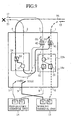
- Fig. 9 illustrates a switching pattern when a fault takes place on the working transmitting path 25
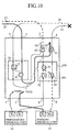
- Fig. 10 illustrates a switching pattern when a fault takes place on the working receiving path 15. In either case, switching of the preparatory transmitted optical signal selector 12 and/or of the working received optical signal selector 22 can implement the operation of the different switching patterns.
- the optical signal from the working terminal unit 13 is transmitted through the Add(WRK) port 5, working Add/Drop switch 41, working transmitted optical signal splitter 11, preparatory transmitted optical signal selector 12 and PRTout port 4, and is supplied to the preparatory transmitting path 16.
- the optical signal is received from the working receiving path 15 by the working terminal unit 13 through the WRKin port 1, working Add/Drop switch 41, working received optical signal selector 22 and Drop(WRK) port 6, or is received from the preparatory receiving path 17 by the preparatory terminal unit 14 through the PRTin port 3, preparatory Add/Drop switch 42, preparatory receiving optical splitter 31, preparatory receiving optical gate 32 and Drop(PRT) port 8.
- the optical signal transmitted via the preparatory receiving path 17 is received by the working terminal unit 13 by capturing it from the PRTin port 3, and by conveying it to the working terminal unit 13 through the preparatory Add/Drop switch 42, preparatory receiving optical splitter 31, working received optical signal selector 22 and Drop(WRK) port 6.
- the optical signal is sent from the working terminal unit 13 to the working transmitting path 25 through the Add(wRK) port 5, working Add/Drop switch 41, working transmitted optical signal splitter 11 and WRKout port 2, or is sent from the preparatory terminal unit 14 to the preparatory transmitting path 16 through the Add(PRT) port 7, preparatory Add/Drop switch 42, preparatory transmitted optical signal selector 12 and PRTout port 4.
- the present example 4 employs the receiving section 23b of the example 3 as the receiving section, using the receiving section 23 or 23a of the example 1 or 2 can implement the same operation.
- the present example 4 can make full use of the total transmission capacity of both the working transmitting path 25 and working receiving path 15 and of both the preparatory transmitting path 16 and preparatory receiving path 17 in the faultless state. Furthermore, in case of a fault, the communications of the working transmitting path 25 or the working receiving path 15 are detoured to the preparatory transmitting path 16 or preparatory receiving path 17. This offers an advantage of being able to save the communications of the working system.
- the optical switching system 18c can be constructed by adding to the number of the optical space switches required in the examples 1-3 the two 2x2 optical space switches (the working Add/Drop switch 41 and preparatory Add/Drop switch 42). This offers an advantage of being able to reduce the number of unit switches as compared with the conventional example 1, thereby shrinking the packaging size.
- the working Add/Drop switch 41 and preparatory Add/Drop switch 42 added to carry out the Add/Drop functions in the present example 4 are composed of the separate optical space switches corresponding to the working and preparatory systems each. This enables the two systems to be mounted on separate boards. Accordingly, even if a fault takes place in the Add/Drop switch of one of the systems, and a recovery job involving the board removal is required, it is unnecessary to remove the optical space switch of the other system. This offers an advantage of being able to prevent the services of the faultless system from being interrupted.
- Fig. 11 is a block diagram showing a configuration of an embodiment of the optical switching system in accordance with the present invention.
- each reference numeral 18d designates an optical switching system of the present embodiment
- 81 designates a span switching means for switching between a working path and a preparatory path in the same section on a West side transmission path
- 82 designates an East side span switching means
- 83 and 84 each designate a ring switching means (first and second ring switching means) for switching between the sections themselves on the transmission path
- 85 and 86 each designate a working terminal unit
- 87 designates a West side PRT in/out port
- 88 designates a West side WRK in/out port
- 89 designates an East side PRT in/out port
- 90 designates an East side WRK in/out port
- 91 designates a West side Add/Drop(PRT) port (Add(PRT) port and Drop(PRT) port)
- 92 designates a West side Add/D
- the working terminal unit 85 connected to the West side Add/Drop(WRK) port 92 of the optical switching system 18d is bidirectionally connected with the working terminal unit 86 via the ring switching means 83, West side span switching means 81 and working path 95.
- the span switching means 81 carries out the span switching through the steps as described in the examples 1-4.
- the span switching can be carried out between the two optical switching systems 18d adjacent to the fault section. Even if a plurality of working path faults take place between the end nodes carrying out the communications, their recovery can be implemented by the span switching in that section.
- the path switching is carried out by the end nodes when the fault takes place on the transmission path 115 only.
- the present embodiment carries out the span switching independently for each path between the adjacent nodes. This offers an advantage of being able to secure the path even in the fault pattern as described above.
- Fig. 12 illustrates a switching state of the ring switching. If faults take place at the same time on the working path 95 and preparatory path 96 in the same section, the ring switching means 83 carries out the switching to the reverse direction preparatory path 96 to save the communication.
- the ring switching function is equivalent to the switching of the conventional example as illustrated in Fig. 2(3) .
- the optical switching system comprises in the transmitting section the preparatory transmitted optical signal selector and working transmitted optical signal splitter, each of which can be implemented using a 1 ⁇ 2 optical space switch, and in the receiving section the receiving optical switch implemented using a 2x2 optical space switch, and the preparatory receiving optical gate implemented using a 1 ⁇ 2 optical space switch.
- the optical switching system is preferably applied to the path switching of the network interconnecting a plurality of nodes through the working path and preparatory path conveying optical signals.
Landscapes
- Engineering & Computer Science (AREA)
- Computer Networks & Wireless Communication (AREA)
- Signal Processing (AREA)
- Optical Communication System (AREA)
Applications Claiming Priority (2)
| Application Number | Priority Date | Filing Date | Title |
|---|---|---|---|
| JP24579598A JP3553385B2 (ja) | 1998-08-31 | 1998-08-31 | 光スイッチング装置 |
| EP99940561A EP1028550B1 (de) | 1998-08-31 | 1999-08-30 | Optischer schalter |
Related Parent Applications (1)
| Application Number | Title | Priority Date | Filing Date |
|---|---|---|---|
| EP99940561A Division EP1028550B1 (de) | 1998-08-31 | 1999-08-30 | Optischer schalter |
Publications (2)
| Publication Number | Publication Date |
|---|---|
| EP1926342A2 true EP1926342A2 (de) | 2008-05-28 |
| EP1926342A3 EP1926342A3 (de) | 2008-11-26 |
Family
ID=17138955
Family Applications (2)
| Application Number | Title | Priority Date | Filing Date |
|---|---|---|---|
| EP08075024A Withdrawn EP1926342A3 (de) | 1998-08-31 | 1999-08-30 | Optisches Schaltsystem |
| EP99940561A Expired - Lifetime EP1028550B1 (de) | 1998-08-31 | 1999-08-30 | Optischer schalter |
Family Applications After (1)
| Application Number | Title | Priority Date | Filing Date |
|---|---|---|---|
| EP99940561A Expired - Lifetime EP1028550B1 (de) | 1998-08-31 | 1999-08-30 | Optischer schalter |
Country Status (5)
| Country | Link |
|---|---|
| US (1) | US6434288B1 (de) |
| EP (2) | EP1926342A3 (de) |
| JP (1) | JP3553385B2 (de) |
| DE (1) | DE69942662D1 (de) |
| WO (1) | WO2000013347A1 (de) |
Families Citing this family (16)
| Publication number | Priority date | Publication date | Assignee | Title |
|---|---|---|---|---|
| US6721508B1 (en) | 1998-12-14 | 2004-04-13 | Tellabs Operations Inc. | Optical line terminal arrangement, apparatus and methods |
| WO2001030006A1 (en) * | 1999-10-18 | 2001-04-26 | Nortel Networks Limited | Communication network for transmitting and restoring an optical signal |
| JP3686824B2 (ja) * | 2000-05-29 | 2005-08-24 | 株式会社日立コミュニケーションテクノロジー | 光1:1切替装置 |
| JP4592170B2 (ja) * | 2000-10-18 | 2010-12-01 | 株式会社東芝 | 光伝送装置 |
| DE10104704A1 (de) * | 2001-02-02 | 2002-09-26 | Siemens Ag | Verfahren und elektro-optische Schaltungsanordnung zur Leitungsprotektion in einer WDM-Datenübertragungsstrecke |
| US6832014B1 (en) * | 2002-02-08 | 2004-12-14 | Marconi Communications, Inc. | Backplane wire and noise eliminator tube |
| GB2386804A (en) * | 2002-03-22 | 2003-09-24 | Motorola Inc | Communications network node access switches |
| US7231148B2 (en) * | 2002-03-28 | 2007-06-12 | Fujitsu Limited | Flexible open ring optical network and method |
| US7116905B2 (en) * | 2002-03-27 | 2006-10-03 | Fujitsu Limited | Method and system for control signaling in an open ring optical network |
| US7336901B1 (en) * | 2004-02-24 | 2008-02-26 | Avanex Corporation | Reconfigurable optical add-drop multiplexers employing optical multiplex section shared protection |
| JP4593267B2 (ja) * | 2004-12-28 | 2010-12-08 | 富士通株式会社 | 光ノードおよび光分岐挿入装置 |
| JP5682353B2 (ja) * | 2011-02-14 | 2015-03-11 | 富士通株式会社 | 伝送装置およびネットワークプロテクション方法 |
| US9170377B2 (en) * | 2011-07-18 | 2015-10-27 | Hewlett-Packard Development Company, L.P. | Optical interconnect |
| US9519019B2 (en) * | 2013-04-11 | 2016-12-13 | Ge Aviation Systems Llc | Method for detecting or predicting an electrical fault |
| CN108007481B (zh) * | 2017-12-07 | 2020-06-05 | 上海第二工业大学 | 一种利用光学非互易器件进行光传感的系统 |
| CN111856481B (zh) * | 2020-07-29 | 2021-07-06 | 杭州视光半导体科技有限公司 | 一种扫描器以及应用该扫描器的同轴和非同轴雷达系统 |
Family Cites Families (12)
| Publication number | Priority date | Publication date | Assignee | Title |
|---|---|---|---|---|
| US5442623A (en) * | 1992-08-17 | 1995-08-15 | Bell Communications Research, Inc. | Passive protected self healing ring network |
| JPH06209284A (ja) * | 1993-01-12 | 1994-07-26 | Nippon Telegr & Teleph Corp <Ntt> | 光スイッチングモジュール |
| JPH08149088A (ja) * | 1994-11-17 | 1996-06-07 | Nippon Telegr & Teleph Corp <Ntt> | 光多重通信網およびノード装置 |
| JPH08293854A (ja) * | 1995-04-24 | 1996-11-05 | Kokusai Denshin Denwa Co Ltd <Kdd> | 波長多重による予備回線を有する光海底ケーブル装置およびその通信方法 |
| JPH11508427A (ja) * | 1995-06-26 | 1999-07-21 | テレフオンアクチーボラゲツト エル エム エリクソン(パブル) | 自己回復網 |
| JPH10112700A (ja) * | 1996-10-04 | 1998-04-28 | Nec Corp | リング構成の波長分割多重光伝送装置 |
| JPH10126350A (ja) * | 1996-10-15 | 1998-05-15 | Nec Corp | 光ネットワーク、光分岐挿入ノードおよび障害回復方式 |
| WO1998034363A1 (en) * | 1997-01-31 | 1998-08-06 | Telefonaktiebolaget Lm Ericsson (Publ) | Wdm traffic protection |
| US5986783A (en) * | 1997-02-10 | 1999-11-16 | Optical Networks, Inc. | Method and apparatus for operation, protection, and restoration of heterogeneous optical communication networks |
| JP3285138B2 (ja) * | 1997-10-20 | 2002-05-27 | 富士通株式会社 | リングネットワークにおける伝送装置 |
| JP3639109B2 (ja) * | 1998-04-02 | 2005-04-20 | 富士通株式会社 | 光伝送装置、光伝送システム及び光端局 |
| JP2000112700A (ja) * | 1998-10-05 | 2000-04-21 | Canon Inc | データベース化装置、印刷システム、印刷装置の状態変化表示方法、及びコンピュータ読み取り可能な記憶媒体 |
-
1998
- 1998-08-31 JP JP24579598A patent/JP3553385B2/ja not_active Expired - Fee Related
-
1999
- 1999-08-30 US US09/530,448 patent/US6434288B1/en not_active Expired - Fee Related
- 1999-08-30 EP EP08075024A patent/EP1926342A3/de not_active Withdrawn
- 1999-08-30 DE DE69942662T patent/DE69942662D1/de not_active Expired - Lifetime
- 1999-08-30 WO PCT/JP1999/004682 patent/WO2000013347A1/ja not_active Ceased
- 1999-08-30 EP EP99940561A patent/EP1028550B1/de not_active Expired - Lifetime
Non-Patent Citations (2)
| Title |
|---|
| HAMADA, S. ET AL.: "WDM four-fiber ring with add/drop acousto-optic tuneable filter and 4x4 optical switch", OPTICAL FIBER COMMUNICATION CONFERENCE, TECHNICAL DIGEST SERIES, 16 February 1997 (1997-02-16), pages 313 - 314 |
| UEHARA, D. ET AL.: "Highly reliable and economical WDM ring with optical self-healing and 1:N wavelength protection", LLTH INTERNATIONAL CONFERENCE ON INTEGRATED OPTICS AND OPTICAL FIBRE COMMUNICATIONS, vol. 4, no. 448, 22 September 1997 (1997-09-22), pages 65 - 68, XP006508607 |
Also Published As
| Publication number | Publication date |
|---|---|
| US6434288B1 (en) | 2002-08-13 |
| WO2000013347A1 (en) | 2000-03-09 |
| DE69942662D1 (de) | 2010-09-23 |
| JP3553385B2 (ja) | 2004-08-11 |
| EP1028550B1 (de) | 2010-08-11 |
| JP2000078080A (ja) | 2000-03-14 |
| EP1926342A3 (de) | 2008-11-26 |
| EP1028550A1 (de) | 2000-08-16 |
| EP1028550A4 (de) | 2004-09-08 |
Similar Documents
| Publication | Publication Date | Title |
|---|---|---|
| EP0920153B1 (de) | Ringnetzwerk zur Verteilung von Schutzbetriebsmitteln durch funktionierende Kommunikationswege | |
| US6701085B1 (en) | Method and apparatus for data transmission in the wavelength-division multiplex method in an optical ring network | |
| US6434288B1 (en) | Optical switching system | |
| EP1161014A1 (de) | Selbstschützendes optisches Nachrichtenübertragungs-Ringnetzwerk | |
| JPH10112700A (ja) | リング構成の波長分割多重光伝送装置 | |
| US7133609B2 (en) | Bidirectional WDM self-healing ring network | |
| EP1033003A2 (de) | Verfahren und vorrichtung zum betrieb, schutz und wiederherstellung von heterogenen optischen übertragungsnetzwerken | |
| US6579018B1 (en) | Four-fiber ring optical cross connect system using 4×4 switch matrices | |
| US7123830B2 (en) | WDM self-healing optical ring network | |
| JP2012075115A (ja) | 光通信網用のノード | |
| EP1014613A2 (de) | Verteilter optischer Schutz in einem optischen Kommunikationsnetzwerk | |
| JP4676657B2 (ja) | 光アド・ドロップ多重化装置 | |
| US6594412B2 (en) | Optical add/drop device | |
| US7817918B2 (en) | Path protection method for a WDM network and according node | |
| US6922530B1 (en) | Method and apparatus for optical channel switching in an optical add/drop multiplexer | |
| US7020078B2 (en) | Communication network system and communication network node for use in the same communication network system | |
| US6744760B1 (en) | Node configurations within communication systems | |
| US7085493B2 (en) | Line processing equipment |
Legal Events
| Date | Code | Title | Description |
|---|---|---|---|
| PUAI | Public reference made under article 153(3) epc to a published international application that has entered the european phase |
Free format text: ORIGINAL CODE: 0009012 |
|
| 17P | Request for examination filed |
Effective date: 20080109 |
|
| AC | Divisional application: reference to earlier application |
Ref document number: 1028550 Country of ref document: EP Kind code of ref document: P |
|
| AK | Designated contracting states |
Kind code of ref document: A2 Designated state(s): AT BE CH CY DE DK ES FI FR GB GR IE IT LI LU MC NL PT SE |
|
| AX | Request for extension of the european patent |
Extension state: AL LT LV MK RO SI |
|
| RIN1 | Information on inventor provided before grant (corrected) |
Inventor name: KOBAYASHI, NAOKIC/O KDD CORPORATION Inventor name: KABASHIMA, TAKATOMIC/O KDD CORPORATION Inventor name: MIYAZAKI, TETSUYAC/O KDDI R&D LABORATORIES INC. Inventor name: YAMAMOTO, SHUC/O KDD CORPORATION Inventor name: KITAYAMA, TADAYOSHIC/O MITSUBISHI DENKI K.K. Inventor name: MIZUOCHI, TAKASHIC/O MITSUBISHI DENKI K.K. Inventor name: ICHIBANGASE, HIROSHIC/O MITSUBISHI DENKI K.K. Inventor name: UEMURA, ARITOMOC/O MITSUBISHI DENKI K.K. |
|
| PUAL | Search report despatched |
Free format text: ORIGINAL CODE: 0009013 |
|
| AK | Designated contracting states |
Kind code of ref document: A3 Designated state(s): AT BE CH CY DE DK ES FI FR GB GR IE IT LI LU MC NL PT SE |
|
| AX | Request for extension of the european patent |
Extension state: AL LT LV MK RO SI |
|
| 17Q | First examination report despatched |
Effective date: 20090130 |
|
| AKX | Designation fees paid |
Designated state(s): DE FR GB |
|
| GRAP | Despatch of communication of intention to grant a patent |
Free format text: ORIGINAL CODE: EPIDOSNIGR1 |
|
| STAA | Information on the status of an ep patent application or granted ep patent |
Free format text: STATUS: THE APPLICATION IS DEEMED TO BE WITHDRAWN |
|
| 18D | Application deemed to be withdrawn |
Effective date: 20110328 |