EP1926112A1 - Elektrisches Kontaktsystem für ein elektrisches Schaltgerät - Google Patents
Elektrisches Kontaktsystem für ein elektrisches Schaltgerät Download PDFInfo
- Publication number
- EP1926112A1 EP1926112A1 EP06405490A EP06405490A EP1926112A1 EP 1926112 A1 EP1926112 A1 EP 1926112A1 EP 06405490 A EP06405490 A EP 06405490A EP 06405490 A EP06405490 A EP 06405490A EP 1926112 A1 EP1926112 A1 EP 1926112A1
- Authority
- EP
- European Patent Office
- Prior art keywords
- contact
- electrical
- unit
- force
- bimetallic
- Prior art date
- Legal status (The legal status is an assumption and is not a legal conclusion. Google has not performed a legal analysis and makes no representation as to the accuracy of the status listed.)
- Withdrawn
Links
- 230000000694 effects Effects 0.000 claims abstract description 17
- 230000001747 exhibiting effect Effects 0.000 claims 2
- 230000013011 mating Effects 0.000 description 14
- 229910000906 Bronze Inorganic materials 0.000 description 4
- 239000010949 copper Substances 0.000 description 4
- 238000010438 heat treatment Methods 0.000 description 4
- 239000011701 zinc Substances 0.000 description 4
- 239000010974 bronze Substances 0.000 description 3
- 230000008859 change Effects 0.000 description 3
- 230000006872 improvement Effects 0.000 description 3
- 239000000463 material Substances 0.000 description 3
- 238000000034 method Methods 0.000 description 3
- 230000008569 process Effects 0.000 description 3
- RYGMFSIKBFXOCR-UHFFFAOYSA-N Copper Chemical compound [Cu] RYGMFSIKBFXOCR-UHFFFAOYSA-N 0.000 description 2
- TVZPLCNGKSPOJA-UHFFFAOYSA-N copper zinc Chemical compound [Cu].[Zn] TVZPLCNGKSPOJA-UHFFFAOYSA-N 0.000 description 2
- 230000009467 reduction Effects 0.000 description 2
- 229910052709 silver Inorganic materials 0.000 description 2
- 239000004332 silver Substances 0.000 description 2
- 229910000851 Alloy steel Inorganic materials 0.000 description 1
- 229910017518 Cu Zn Inorganic materials 0.000 description 1
- 229910017752 Cu-Zn Inorganic materials 0.000 description 1
- 229910017943 Cu—Zn Inorganic materials 0.000 description 1
- HCHKCACWOHOZIP-UHFFFAOYSA-N Zinc Chemical compound [Zn] HCHKCACWOHOZIP-UHFFFAOYSA-N 0.000 description 1
- 238000005299 abrasion Methods 0.000 description 1
- 230000003679 aging effect Effects 0.000 description 1
- 229910052782 aluminium Inorganic materials 0.000 description 1
- XAGFODPZIPBFFR-UHFFFAOYSA-N aluminium Chemical compound [Al] XAGFODPZIPBFFR-UHFFFAOYSA-N 0.000 description 1
- 238000000418 atomic force spectrum Methods 0.000 description 1
- 239000002131 composite material Substances 0.000 description 1
- 229910052802 copper Inorganic materials 0.000 description 1
- KUNSUQLRTQLHQQ-UHFFFAOYSA-N copper tin Chemical compound [Cu].[Sn] KUNSUQLRTQLHQQ-UHFFFAOYSA-N 0.000 description 1
- 230000003247 decreasing effect Effects 0.000 description 1
- 230000001419 dependent effect Effects 0.000 description 1
- 238000011982 device technology Methods 0.000 description 1
- 238000010586 diagram Methods 0.000 description 1
- 208000001848 dysentery Diseases 0.000 description 1
- 230000000670 limiting effect Effects 0.000 description 1
- 238000012423 maintenance Methods 0.000 description 1
- 239000002184 metal Substances 0.000 description 1
- 229910052751 metal Inorganic materials 0.000 description 1
- 150000002739 metals Chemical class 0.000 description 1
- 229910052755 nonmetal Inorganic materials 0.000 description 1
- 230000003647 oxidation Effects 0.000 description 1
- 238000007254 oxidation reaction Methods 0.000 description 1
- 230000000284 resting effect Effects 0.000 description 1
- 238000000926 separation method Methods 0.000 description 1
- 210000002023 somite Anatomy 0.000 description 1
- 230000007480 spreading Effects 0.000 description 1
- 229910052725 zinc Inorganic materials 0.000 description 1
Images


Classifications
-
- H—ELECTRICITY
- H01—ELECTRIC ELEMENTS
- H01H—ELECTRIC SWITCHES; RELAYS; SELECTORS; EMERGENCY PROTECTIVE DEVICES
- H01H1/00—Contacts
- H01H1/50—Means for increasing contact pressure, preventing vibration of contacts, holding contacts together after engagement, or biasing contacts to the open position
- H01H1/504—Means for increasing contact pressure, preventing vibration of contacts, holding contacts together after engagement, or biasing contacts to the open position by thermal means
-
- H—ELECTRICITY
- H01—ELECTRIC ELEMENTS
- H01H—ELECTRIC SWITCHES; RELAYS; SELECTORS; EMERGENCY PROTECTIVE DEVICES
- H01H1/00—Contacts
- H01H1/12—Contacts characterised by the manner in which co-operating contacts engage
- H01H1/14—Contacts characterised by the manner in which co-operating contacts engage by abutting
- H01H1/24—Contacts characterised by the manner in which co-operating contacts engage by abutting with resilient mounting
- H01H1/26—Contacts characterised by the manner in which co-operating contacts engage by abutting with resilient mounting with spring blade support
Definitions
- the invention relates to the field of switching device technology, in particular relates to an electrical contact system for producing an electrical contact in an electrical switching device and to an electrical switching device according to the preamble of the independent claims.
- Silver are surface-coated and in which the contact and the mating contact of the switch are resiliently pressed against each other in order to achieve an increase in the electrical conductivity in the contact area.
- European Patent EP0844631 For example, there is known a switchable electrical contact system for a grounding switch having a contact pin and a tulip-shaped mating contact. To produce an electrical contact of the mating contact is pushed with its resilient contact fingers on the contact pin, wherein the individual contact fingers press resiliently on the contact pin.
- the electrical contact between contact and mating contact is in need of improvement.
- the contact resistance is increased and thus the electrical conductivity is not optimal, resulting in wear and unwanted heating of the contacts.
- the contacts also often wear in the surface area, which for example in surface-coated contacts or contacts which work in a SF 6 gas atmosphere, contributes to reducing the electrical conductivity and thus also leads to undesirable heating in the contact area.
- a shortened life and a high maintenance of the switching device are her consequence.
- the present invention seeks to alleviate at least some of the above problems.
- the object is achieved by an electrical contact system and by an electrical switching device having the features of the independent claims.
- an electrical contact system of an electrical switching device which has a first and a second contact unit, wherein a contact force acts between the first and the second contact unit upon electrical contact. Furthermore, means for exerting the contact force are present, ie, in the case of electrical contact, a force is exerted by the first contact unit on the second contact unit or by the second contact unit on the first contact unit or by both contact units against each other.
- the first contact unit is separable from the second contact unit by the distance between the two contact units is increased. The contact separation does not take place via the means for exercising the contact force. In the disconnected state, there is no electrical contact between the first and the second contact unit.
- the inventive electrical contact system is characterized in that the means for exerting the contact force have a thermal expansion effect, which causes an increase in the contact force with increasing temperature of the means, ie when heat is applied to the thermal expansion in the means, which is about the expansion coefficient of the means and describe the temperature change in the media. It is completely irrelevant in what way the means heat is supplied.
- An improvement of the electrical and mechanical contact in the contact area can be achieved in a wide variety of conditions, with high and low contact force.
- the automatic increase in contact pressure with increasing temperature during operation of the switch advantageously leads to a reduction of the contact resistance and thus to an increased conductivity in the contact region.
- the abrasion in the contact region of the contact units of the switch is advantageously reduced by the lower contact force, whereby the service life of the contact units of the switch is markedly increased.
- an electrical switching device in particular a circuit breaker is proposed.
- the electrical switching device comprises an electrical contact system and has the features described in the preceding section or in claim 1.
- Fig. 1 shows a schematic view of a contact finger 12, a leaf spring 13 and an expansion body 15 of a contact unit 10, 20 which are parts of an electrical contact system not shown.
- the leaf spring 13, which extends substantially along the length of the contact finger 12, is fixedly connected at one end to one end of the contact finger 12.
- the expansion body 1 5 is located between the leaf spring 13 and contact fingers 12. It can be clamped, for example between leaf spring 13 and contact fingers 12. If heat is supplied to the contact unit 10, 20, eg caused by the flow of electrical current or by the medium surrounding the contact unit, the volume of expansion of the expansion body, which consists, for example, of an aluminum-bronze alloy and the material of the contact finger, is particularly high 12 and the leaf spring 13, for example a steel alloy, has a comparatively large expansion coefficient.
- FIGS. 2a and 2b respectively show a view of a contact unit 10, 20 of a contact system, not shown, which consists of a bimetallic spring 14 and a contact finger 12.
- the bimetal spring 14 is bent semicircularly at one of its ends and presses at this end on the contact finger 12.
- the contact finger 12 is constructed for example of Metalliamellenstapeln and thus elastically deformable. However, the contact finger 12 can just as easily be formed in one piece and have an elasticity.
- FIG. 2b shows the contact unit 10, 20 after it has been supplied with heat. Due to the different expansion coefficients of the two metals of the bimetallic spring 14, there is a change in shape in the spring 14.
- the bent portion of the spring 14 is widened and thus increases the spring force with which the spring 14 presses the contact finger 12 presses on a mating contact, not shown .
- the spring force of the bimetallic spring 14 and contact fingers 12 and spring 14 return to their initial state, as shown in Fig.2a, founded.Somit characterized in Fig. 2a, 2b contact unit 10th in that the means 14, which is a bimetallic spring, has a thermal expansion effect, which leads to an increase in the contact force.
- FIG 3 shows another embodiment of the contact unit 10, 20 in which the self-resilient contact fingers 18 is made of bimetal.
- the self-resilient contact fingers 18 is made of bimetal.
- the bimetallic contact finger 18 is thus itself a means for increasing the contact force.
- the self-resilient contact finger 18 is regarded as a cantilevered beam, the acting force F of the finger as well as its deflection s from the rest position can be easily calculated for a given geometry.
- the pure spring force without consideration of a bimetallic effect for a cantilevered contact finger and taking into account the aforementioned parameters 34 N.
- the contact pressure of the finger can be increased or decreased by more than 50% compared with a contact finger without bimetallic effect, if the finger has a temperature difference of 60 K. experiences.
- the contact force F caused by the contact finger 12 and the bimetallic spring 14 is increased by more than 300% in comparison with a spring-action contact finger but without additional force caused by the bimetal.
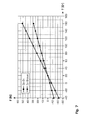
- Figure 7 shows a force-temperature diagram with the calculated force-contact temperature curves for a cantilevered copper-bronze bimetallic contact finger and a copper-zinc bimetallic contact finger.
- Both the spring element 14 and the contact element 18 in this case have a bimetallic effect.
- the spring element 14 and the self-resilient contact element 18 is not completely but only partially made of bimetal to increase the contact force, ie only a portion of the spring element and / or the contact element are made of bimetal.
- an increase in the contact force with increasing temperature can also be achieved by applying material with a suitable coefficient of expansion to the resilient contact element 17 and / or the spring element 12, so that a bimetallic effect is achieved by means of the application.
- the inventive contact system 1 of an electrical switching device shown in Figure 4 is the contact system 1 for each one Druckerpol a generator switch.
- the isolator contact system 1 has a cylindrical contact unit 10 and a cylindrical counter contact formed as a contact unit 20, which axially on the Longitudinal axis A are arranged.
- the electrical contact to the mating contact unit 20 is made via the contact fingers 12 of the contact unit 10, which are arranged annularly on the lateral surface of the contact unit 10 and secured by screw 19.
- the contact surface 23 of the mating contact unit 20 is coated with silver.
- the contact system 1 is closed and the contact fingers 12 are in electrical contact with the contact unit 20, for which purpose the contact fingers 12 are pushed onto the contact surface 23 of the contact unit 20.
- the bimetallic springs 14 of the contact fingers 12 in this case exert a contact pressure with which the contact fingers 12 press against the contact surface 23 of the mating contact unit 20.
- the contact force of the bimetallic spring 14 is increased by the fact that the contact system 1 is heated by the current flow in the contact units 10, 20 and due to the contact resistance between the contact units 10, 20.
- the increased contact pressure in turn leads to a better electrical conductivity, ie a reduction of the contact resistance between the two contact units 10, 20 and thus to a decrease in the temperature in the contact system 1.
- the contact system 1 assumes a more stable operating condition, it stabilizes automatically. Furthermore, a self-healing process occurs at the contact surfaces 16, 23. This self-healing process consists in automatically reducing the increase in contact resistance caused by oxidation or aging effects. Due to the increased contact resistance at the contact surfaces 16, 23 there is an increase in temperature in the contact units 10, 20 and thus an increased contact pressure of the contact fingers 1 2 on the contact unit 20. The increased contact force in turn improves the electrical contact between the contact surfaces 16, 23 and thus reduces the contact resistance. This improvement of the electrical conductivity at the contact surfaces 16, 23 to be understood as a self-healing effect thus likewise leads to more stable operating conditions of the contact system 1.
- FIG. 5 shows the rated current contact system 1 of a generator switch with a cylindrical contact unit 10, a cylindrical mating contact unit 20 and a plurality of contact fingers 12 which are arranged annularly around the contact unit 20 and held by bimetallic springs 14 in the circumferential recess 25.
- Each contact finger 12 has a bimetallic spring 14.
- the bimetallic springs 14 rest on both sides in the recess 25 and are shaped such that a projection in the center of the springs 14 engages in a recess 26 of the contact fingers 12.
- the selective intermeshing of spring 14 and contact fingers 12 allows a tilting movement of the contact finger 12 about its attachment point. In the closed state of the switch is ever one end of the contact finger 12 on the contact unit 10 and on the Schwarzköntaktmaschine 20 on.
- the heating of the bimetallic springs 14 causes the bimetallic effect in the springs 14, an increase in the contact force between the contact fingers 12 and contact units 10, 20th
- the illustrated embodiments may be further varied without departing from the scope of the claims as defined in the claims.
- the contact finger 12 and the bimetallic spring 14 in FIG 6 also consist of one piece and have the properties of a bimetallic spring. Furthermore, it is not necessary that the spring elements 14 or the contact fingers 12, 18 are made of bimetal. Both contact fingers 12, 18 and spring elements 14 may consist of a non-metal or other composite material, which has a bimetal effect.
Landscapes
- Thermally Actuated Switches (AREA)
- Contacts (AREA)
Abstract
Description
- Die Erfindung bezieht sich auf das Gebiet der Schaltgerätetechnik, insbesondere bezieht Sie sich auf ein elektrisches Kontaktsystem zur Herstellung eines elektrischen Kontaktes in einem elektrischen Schaltgerät und auf ein elektrisches Schaltgerät gemäss dem Oberbegriff der unabhängigen Patentansprüche.
- Elektrische Schalter mit elektrischen Kontaktsystemen werden allgemein genutzt, um den Energiefluss in einem Energieversorgungsnetz zu unterbrechen und wiederherzustellen. Solche Schalter werden auf allen Spannungsebenen des Energienetzes eingesetzt. Während des Normalbetriebes muss der Widerstand des Schalters möglichst niedrig sein, um entsprechende Leistungsverluste niedrig zu halten. Im Schaltfall muss der Schalter grosse Ströme im Normalbetrieb und sogar noch grössere Ströme im Kurzschlussfall schalten können. Aus dem Stand der Technik sind nun Schalter bekannt, bei denen die Kontakte mit einer dünnen Schicht
- Silber oberflächenbeschichtet sind und bei denen der Kontakt und der Gegenkontakt des Schalters federnd aufeinander gepresst werden, um eine Erhöhung der elektrischen Leitfähigkeit im Kontaktbereich zu erreichen. Aus der
Europäischen Patentschrift EP0844631 ist ein schaltbares elektrisches Kontaktsystem für einen Erdungsschalter bekannt, welches einen Kontaktstift und einen tulpenförmigen Gegenkontakt aufweist. Zur Herstellung eines elektrischen Kontaktes wird der Gegenkontakt mit seinen federnden Kontaktfingern auf den Kontaktstift geschoben, wobei die einzelnen Kontaktfinger federnd auf den Kontaktstift drücken. - Bei diesem und anderen elektrischen Kontaktsystemen ist die elektrische Kontaktierung zwischen Kontakt und Gegenkontakt verbesserungswürdig. Bei beispielsweise verschmutzten oder oxidierten Kontakten ist der Kontaktwiderstand erhöht und damit ist die elektrische Leitfähigkeit nicht optimal, was zu Verschleisserscheinungen und einer unerwünschten Erwärmung an den Kontakten führt. Durch den Betrieb des Schalters weisen die Kontakte auch oft Abrieb im Oberflächenbereich auf, was beispielsweise bei oberflächenbeschichteten Kontakten oder Kontakten welche in einer SF6 Gasatmosphäre arbeiten, zur Verminderung der elektrischen Leitfähigkeit beiträgt und damit ebenfalls zu einer unerwünschten Erwärmung im Kontaktbereich führt. Ein verkürzte Lebensdauer und ein hoher Wartungsaufwand des Schaltgerätes sind sie Folge.
- Die vorliegende Erfindung versucht zumindest einige der oben genannten Probleme zu mindern. Die Aufgabe wird gelöst durch ein elektrisches Kontaktsystem und durch ein elektrisches Schaltgerät mit den Merkmalen der unabhängigen Patentansprüche.
- Gemäss einem Aspekt der Erfindung wird ein elektrisches Kontaktsystem eines elektrischen Schaltgerätes vorgeschlagen, das eine erste und eine zweite Kontakteinheit aufweist, wobei zwischen der ersten und der zweiten Kontakteinheit bei elektrischem Kontakt eine Kontaktkraft wirkt. Weiterhin sind Mittel zur Ausübung der Kontaktkraft vorhanden, d. h. im Falle des elektrischen Kontaktes wird mit den Mitteln eine Kraft von der ersten Kontakteinheit auf die zweite Kontakteinheit oder von der zweiten Kontakteinheit auf die erste Kontakteinheit oder von beiden Kontakteinheiten gegeneinander ausgeübt. Die erste Kontakteinheit ist von der zweiten Kontakteinheit trennbar, indem der Abstand zwischen beiden Kontakteinheiten vergrössert wird. Die Kontakttrennung erfolgt dabei nicht über die Mittel zur Ausübung der Kontaktkraft. Im getrennten Zustand gibt es keinen elektrischen Kontakt zwischen der ersten und der zweiten Kontakteinheit. Das erfindungsgemässe elektrische Kontaktsystem ist dadurch gekennzeichnet, dass die Mittel zur Ausübung der Kontaktkraft einen thermischen Ausdehnungseffekt aufweisen, welcher eine Erhöhung der Kontaktkraft mit steigender Temperatur der Mittel bewirkt, d.h. bei Wärmezufuhr kommt es zur Wärmedehnung in den Mitteln, welche sich über den Ausdehnungskoeffizienten der Mittel und die Temperaturänderung in den Mitteln beschreiben lässt. Dabei ist es völlig unerheblich, auf welche Art den Mitteln Wärme zugeführt wird. Eine Verbesserung des elektrischen und mechanischen Kontaktes im Kontaktbereich kann bei unterschiedlichsten Bedingungen, bei hoher als auch niedriger Kontaktkraft erzielt werden. Die selbsttätige Kontaktkräfterhöhung mit steigender Temperatur während des Betriebes des Schalters führt vorteilhaft zu einer Erniedrigung des Kontaktwiderstandes und damit zu einer erhöhten Leitfähigkeit im Kontaktbereich. Weiterhin wird beim Einschaltvorgang vorteilhaft der Abrieb im Kontaktbereich der Kontakteinheiten des Schalters durch die geringere Kontaktkraft vermindert, wodurch die Lebensdauer der Kontakteinheiten des Schalters deutlich erhöht wird.
- Gemäss einem weiteren Aspekt der Erfindung wird ein elektrisches Schaltgerät, insbesondere ein Leistungsschalter vorgeschlagen. Das elektrische Schaltgerät umfasst ein elektrisches Kontaktsystem und weist die im vorangegangenen Abschnitt bzw. im Anspruch 1 beschriebenen Merkmale auf.
- Weitere Vorteile, Merkmale, Aspekte und Details der Erfindung ergeben sich aus den Unteransprüchen, der Beschreibung und den Figuren.
- Im folgenden wird der Erfindungsgegenstand anhand von bevorzugten Ausführungsbeispielen, welche in den beiliegenden Zeichnungen dargestellt sind, näher erläutert. Es zeigen schematisch:
- Fig. 1
- zwei Ansichten einer erfindungsgemässen Kontakteinheit bei unterschiedlichen Temperaturen; in gestrichelter Darstellung: Kontakteinheit bei erhöhter Temperatur;
- Fig. 2a, b
- jeweils eine Ansicht einer Kontakteinheit mit Bimetallfeder bei unterschiedlicher Temperatur;
- Fig. 3
- eine Ansicht einer Kontakteinheit s deren Kontaktfinger ein Bimetallkontaktfinger ist;
- Fig. 4
- eine Ansicht eines Kontaktsystems mit ringförmig angeordneten erfindungsgemässen Kontaktfingern und einem zylinderförmigen Gegenkontakt;
- Fig. 5
- Ansicht einer Kontakteinheit mit Bimetallkontaktfeder und Bimetallgegenkontaktfeder;
- Fig. 6
- Ansicht eines Kontaktsystems, bei dem die ringförmig angeordneten Kontakte von Bimetallfedern gehalten werden;
- Fig. 7
- Berechnete Kontakttemperatur-Kraft Kurve für zwei Kontaktfinger aus unterschiedlichem Bimetallmaterial.
- Die in den Zeichnungen verwendeten Bezugszeichen und deren Bedeutung sind in der Bezugszeichenliste zusammengefasst aufgelistet. Grundsätzlich sind in den Figuren gleiche oder gleichwirkende Teile mit gleichen oder ähnlichen Bezugszeichen versehen. Für das Verständnis der Erfindung nicht wesentliche Teile sind zum Teil nicht dargestellt. Die beschriebenen Ausführungsbeispiele stehen beispielhaft für den Erfindungsgegenstand und haben keine beschränkende Wirkung.
- Fig. 1 zeigt in schematischer Ansicht einen Kontaktfinger 12, eine Blattfeder 13 und einen Dehnungskörper 15 einer Kontakteinheit 10, 20 welche Teile eines nicht weiter dargestellten elektrischen Kontaktsystems sind. Die Blattfeder 13, die sich im Wesentlichen entlang der Länge des Kontaktfingers 12 erstreckt, ist an einem Ende fest mit einem Ende des Kontaktfingers 12 verbunden. Der Dehnungskörper 1 5 befindet sich zwischen Blattfeder 13 und Kontaktfinger 12. Er kann beispielsweise zwischen Blattfeder 13 und Kontaktfinger 12 eingeklemmt sein. Wird der Kontakteinheit 10, 20 Wärme zugeführt, z.B. verursacht durch elektrischen Stromfluss oder durch das Medium welches die Kontakteinheit umgibt, kommt es in besonderem Masse zu einer volumenmässigen Ausdehnung des Dehnungskörper, welcher beispielsweise aus einer Aluminium-Bronze Legierung besteht und gegenüber dem Material des Kontaktfingers 12 und der Blattfeder 13, beispielsweise einer Stahllegierung, einen vergleichsweise grossen Ausdehnungskoeffizienten aufweist. Die Wärmezufuhr und damit die Temperaturerhöhung des Dehnungskörpers führt somit zu einer Spreizung von Kontaktfinger 12 und Blattfeder 13 (Strich-Punkt Darstellung). Mittels der durch Wärmezufuhr verursachten Aufspreizung wird die Kontaktkraft, die vom Kontaktfinger 12 auf einen nicht weiter dargestellten Gegenkontakt ausgeübt wird, erhöht.
- Figuren 2a und 2b zeigen jeweils eine Ansicht einer Kontakteinheit 10, 20 eines nicht dargestellten Kontaktsystems, welches aus einer Bimetallfeder 14 und einem Kontaktfinger 12 besteht. Die Bimetallfeder 14 ist an einem ihrer Enden halbkreisförmig gebogen und drückt an diesem Ende auf den Kontaktfinger 12. Der Kontaktfinger 12 ist beispielsweise aus Metalliamellenstapeln aufgebaut und damit elastisch verformbar. Der Kontaktfinger 12 kann aber genauso gut einstückig geformt sein und eine Elastizität aufweisen. Figur 2b zeigt die Kontakteinheit 10, 20 nachdem ihr Wärme zugeführt wurde. Auf Grund der unterschiedlichen Ausdehnungskoeffizienten der zwei Metalle der Bimetallfeder 14, kommt es zur Formänderung in der Feder 14. Der gebogene Bereich der Feder 14 wird aufgeweitet und erhöht damit die Federkraft, mit welcher die Feder 14 den Kontaktfinger 12 drückt auf einen nicht dargestellten Gegenkontakt drückt. Bei Abgabe der aufgenommenen Wärme der Kontakteinheit 10, 20 verringert sich die Federkraft der Bimetallfeder 14 und Kontaktfinger 12 und Feder 14 kehren in ihren Ausgangszustand, wie in Fig.2a dargestellt, zurück.Somit zeichnet sich die in Fig. 2a, 2b dargestellte Kontakteinheit 10 dadurch aus, dass das Mittel 14, welches eine Bimetallfeder ist, einen thermischen Ausdehnungseffekt aufweist, der zu einer Erhöhung der Kontaktkraft führt.
- Figur 3 zeigt eine weitere Ausführungsform der Kontakteinheit 10, 20 bei welcher der selbst federnde Kontaktfinger 18 aus Bimetall ist. Somit sind beide Funktionen, die des elektrischen Kontaktierens und die der Erhöhung der Kontaktkraft durch eine Bimetallfeder in dem einzigen Element, dem Kontaktfinger 18 vereinigt. Der Bimetallkontaktfinger 18 ist somit selbst ein Mittel zur Erhöhung der Kontaktkraft. Wird der selbst federnde Kontaktfinger 18 als einseitig eingespannter Balken angesehen, lassen sich auf einfache Weise die wirkende Kraft F des Fingers sowie seine Auslenkung s aus der Ruhelage für eine gegebene Geometrie berechen. Die Auslenkung s des Fingers aus der Ruhrlage ergibt sich auf Grund unterschiedlicher thermischen Ausdehnung im Bimetall wie folgt:

wobei α der Ausdehnungskoeffizient für z.B. Kupfer, Aluminium-Bronze, und Zink ist:


und L0 die Länge des Bimetallbalkens sowie ΔT seine Temperaturdifferenz. Mit Werten für ΔT =60 K und L0 = 72mm ergibt sich für die Längenänderung L bzw. die Auslenkung s des Balkens:


- Die wirkende Kraft F auf den einseitig gespannten Bimetallbalken wie in Figur 3 dargestellt, ergibt sich aus dem Produkt seines Elastizitätsmoduls E mit dem axialen Flächenträgheitsmoment Ja und seiner Auslenkung s, sowie dem Quotienten aus seiner Länge L0:

- Als Flächenträgheitsmoment Ja für eine rechteckige Geometrie des Fingers ergibt sich:

- Für die Elastitizitätsmodule wurden die folgenden Werte angenommen:


- Mit einem daraus folgenden Mittelwert von Pa = 8*104 N/mm2 ergibt sich für ein Cu-Zn Bimetall bei einem Temperaturunterschied von 60 K eine Kraft von:

- Im Vergleich dazu beträgt die reine Federkraft ohne Berücksichtigung eines Bimetalleffektes für einen einseitig eingespannten Kontaktfinger und unter Berücksichtigung der vorgenannten Parameter 34 N.
Somit lässt sich mit einem einseitig eingespannten Kontaktfinger 12, 18, welcher aus Bimetall ist und die oben genannten Parameter hat, im Vergleich zu einem Kontaktfinger ohne Bimetalleffekt die Anpresskraft des Fingers um über 50% erhöhen bzw erniedrigen, wenn der Finger einen Temperaturunterschied von 60 K erfährt. - Für einen Kontaktfinger 12, der mittels einer beidseitig aufliegenden Bimetallfeder 14, wie in Figur 6 dargestellt, unterstützt wird, berechnet sich die in der Mitte des Fingers wirkende Kraft wie folgt:

- Unter Berücksichtung der vorhergehend angenommenen Parameter ergibt sich somit für die auf den Gegenkontakt, wirkende Kraft:

- Somit ist die durch den Kontaktfinger 12 und die Bimetallfeder 14 hervorgerufene Anpresskraft F im Vergleich zu einem Kontaktfinger mit Federwirkung aber ohne zusätzliche Kraft verursacht durch das Bimetall, um mehr als 300% erhöht.
- Figur 7 zeigt ein Kraft -Temperatur Diagramm mit den berechneten Kraft - Kontakttemperatur Kurven für einen einseitig eingespannten Kupfer-Bronze Bimetallkontaktfinger und einen Kupfer-Zink Bimetallkontaktfinger.
- In einer weiteren Ausführungsform nicht dargestellt, sind die Mittel zur Erhöhung der Kontaktkraft das Federelement 14 und das selbst federnde Kontaktelement 18, diejenigen Mittel, welche zum Anpressen des ersten Kontakteinheit 10 an die zweite Kontakteinheit 20 dienen. Sowohl das Federelement 14 als auch das Kontaktelement 18 weisen dabei einen Bimetalleffekt auf. In anderen Ausführungsformen wird zur Erhöhung der Kontaktkraft das Federelement 14 und das selbst federnde Kontaktelement 18 nicht vollständig sondern nur teilweise aus Bimetall gefertigt, d.h. nur ein Abschnitt des Federelementes und/ oder des Kontaktelementes sind aus Bimetall.
Eine Erhöhung der Kontaktkraft mit steigender Temperatur kann aber auch dadurch erreicht werden, dass auf das federnde Kontaktelement 17 und/oder auf das Federelement 12 Material mit geeignetem Ausdehnungskoeffizienten aufgebracht wird, so das mittels dem Aufbringen ein Bimetalleffekt erzielt wird. - Das in Figur Fig. 4 dargestellte erfindungsgemässe Kontaktsystem 1 eines elektrischen Schaltgerätes ist das Kontaktsystem 1 für jeweils einen Schalterpol eines Generatorschalters. Das Trenner-Kontaktsystem 1 weist eine zylinderförmige Kontakteinheit 10 und eine als zylinderförmigen Gegenkontakt ausgebildete Kontakteinheit 20 auf, welche axial auf der Längsachse A angeordnet sind. Der elektrische Kontakt zur Gegenkontakteinheit 20 wird über die Kontaktfinger 12 der Kontakteinheit 10 hergestellt, welche ringförmig auf der Mantelfläche der Kontakteinheit 10 angeordnet und durch Schraubverbindungen 19 befestigt sind. Zur Verbesserung der elektrischen Leitfähigkeit ist die Kontaktfläche 23 der Gegenkontakteinheit 20 mit Silber beschichtet. Im Betrieb des Generatorschalters ist das Kontaktsystem 1 geschlossen und die Kontaktfinger 12 befinden sich in elektrischem Kontakt mit der Kontakteinheit 20, wofür die Kontaktfinger 12 auf die Kontaktfläche 23 der Kontakteinheit 20 geschoben werden. Die Bimetallfedern 14 der Kontaktfinger 12 üben dabei eine Anpresskraft auf, mit der die Kontaktfinger 12 auf die Kontaktfläche 23 der Gegenkontakteinheit 20 drücken. Im Betrieb des Generatorschalters wird die Kontaktkraft der Bimetallfeder 14 dadurch erhöht, dass sich das Kontaktsystem 1 durch den Stromfluss in den Kontakteinheiten 10, 20 und auf Grund des Kontaktwiderstandes zwischen den Kontakteinheiten 10, 20 erwärmt. Die erhöhte Anpresskraft führt wiederum zu einer besseren elektrischen Leitfähigkeit, also einer Verringerung des Kontaktwiderstandes zwischen beiden Kontakteinheiten 10, 20 und damit zu einem Absinken der Temperatur im Kontaktsystem 1. Das Kontaktsystem 1 nimmt dadurch einen stabileren Betriebszustand ein, es stabilisiert sich selbsttätig.
Weiterhin tritt an den Kontaktflächen 16, 23 ein Selbstheilungsprozess auf. Dieser Selbstheilungsprozess besteht darin, dass die durch Oxidation oder durch Alterungseffekte hervorgerufene Vergrösserung des Kontaktwiderstandes selbsttätig erniedrigt wird. Auf Grund des erhöhten Kontaktwiderstandes an den Kontaktflächen 16, 23 kommt es zu einem Temperaturanstieg in den Kontakteinheiten 10, 20 und damit zu einer erhöhten Anpresskraft der Kontaktfinger 1 2 auf die Kontakteinheit 20. Die erhöhte Anpresskraft wiederum verbessert den elektrischen Kontakt zwischen den Kontaktflächen 16, 23 und verringert somit den Kontaktwiderstand. Diese als Selbstheilungseffekt zu verstehende Verbesserung der elektrischen Leitfähigkeit an den Kontaktflächen 16, 23 führt somit ebenfalls zu stabileren Betriebsbedingungen des Kontaktsystems 1. - Bei der in Figur 5 dargestellten Ausführungsform wird sowohl für die Kontakteinheit 10 als auch für die Gegenkontakteinheit 20 ein mit einer Bimetallfeder 14, 22 versehener Fingerkontakt 12, 21 zur elektrischen Kontaktierung verwendet. Im Unterschied zu der in Figur 4 dargestellten Ausführungsform rührt ein durch die Bimetallfeder hervorgerufene Erhöhung der Anpresskraft also von beiden Bimetallfedern 14 und 22 her, so dass sich die Federkräfte beider Federn 14, 22 addieren.
Figur 6 zeigt das Nennstromkontaktsystem 1 eines Generatorschalters mit einer zylinderförmigen Kontakteinheit 10, einer zylinderförmigen Gegenkontakteinheit 20 sowie einer Mehrzahl Kontaktfinger 12 welche ringförmig um die Kontakteinheit 20 angeordnet sind und durch Bimetallfedern 14 in der umlaufenden Ausnehmung 25 gehalten werden. Jeder Kontaktfinger 12 weist eine Bimetallfeder 14 auf. Die Bimetallfedern 14 liegen beidseitig in der Ausnehmung 25 auf und sind derart geformt, dass ein Vorsprung in der Mitte der Federn 14 in eine Aussparung 26 der Kontaktfinger 12 eingreift. Das punktuelle Ineinandergreifen von Feder 14 und Kontaktfinger 12 gestattet eine Kippenbewegung des Kontaktfingers 12 um seine Befestigungsstelle. Im geschlossenen Zustand des Schalters liegt je ein Ende des Kontaktfingers 12 auf der Kontakteinheit 10 bzw. auf der Gegenköntakteinheit 20 auf. Bei Erwärmung des Kontaktsystems 1 und damit der Erwärmung der Bimetallfedern 14 bewirkt der Bimetalleffekt in den Federn 14 eine Erhöhung der Kontaktkraft zwischen Kontaktfingern 12 und Kontakteinheiten 10, 20.
Die gezeigten Ausführungsformen können weiter variiert werden, ohne dass der in den Ansprüchen definierte Schutzumfang verlassen wird.
Beispielweise können der Kontaktfinger 12 und die Bimetallfeder 14 in Figur 6 auch aus einem Stück bestehen und weisen die Eigenschaften einer Bimetallfeder auf. Weiterhin ist es nicht notwendig, dass die Federelemente 14 oder der Kontaktfinger 12, 18 aus Bimetall bestehen. Sowohl Kontaktfinger 12, 18 als auch Federelemente 14 können aus einem Nichtmetall oder sonstigen Verbundwerkstoff bestehen, welches einen Bimetalleffekt aufweist. -
- 1
- Kontaktsystem
- 10
- Kontakteinheit
- 12, 21
- Kontaktfinger, Kontaktelement
- 13, 22
- Feder, Blattfeder, Federelement
- 14
- Bimetallfeder
- 15
- Dehnungskörper
- 16, 23, 27
- Kontaktfläche
- 18
- Bimetallkontaktfinger
- 19
- Schraubverbindung
- 20
- Kontakteinheit, Gegenkontakteinheit
- 25
- Ausnehmung
- 26
- Aussparung
- A
- Achse
Claims (12)
- Elektrisches Kontaktsystem (1) eines elektrisches Schaltgerätes mit einer ersten Kontakteinheit (10) und einer zweiten Kontakteinheit (20), wobei zwischen der ersten (10) und der zweiten (20) Kontakteinheit bei elektrischem Kontakt eine Kontaktkraft wirkt, wobei Mittel (13,14,15,18) zur Ausübung der Kontaktkraft vorhanden sind, und wobei die erste Kontakteinheit (10) von der zweiten Kontakteinheit (20) trennbar ist, dadurch gekennzeichnet, dass die Mittel (14,15,18) einen thermischen Ausdehnungseffekt aufweisen, welcher eine Erhöhung der Kontaktkraft mit steigender Temperatur der Mittel (14,15,18) bewirkt.
- Elektrisches Kontaktsystem (1) nach Anspruch 1, dadurch gekennzeichnet, dass der thermische Ausdehnungseffekt ein Bimetalleffekt ist.
- Elektrisches Kontaktsystem (1) nach Anspruch 1 oder 2, dadurch gekennzeichnet, dass die bimetalleffektaufweisenden Mittel (13,14;1 5,18) Bimetalle sind.
- Elektrisches Kontaktsystem (1) nach einem der Ansprüche 2-3, dadurch gekennzeichnet, dass die Mittel (13,15;14,18) zur Erhöhung der Kontaktkraft ein den thermischen Ausdehnungseffekt aufweisendes Bimetallfederelement (14) zum Anpressen eines ersten Kontaktelementes (12) der ersten Kontakteinheit (10) an eine zweite Kontakteinheit (20) umfassen.
- Elektrisches Kontaktsystem (1) nach einem der vorhergehenden Ansprüche, dadurch gekennzeichnet, dass die Mittel (13,14;15,18) zur Erhöhung der Kontaktkraft ein selbst federndes, den thermischen Ausdehnungseffekt aufweisendes Kontaktelement (18), insbesondere ein Bimetallkontaktelement (18), der Kontakteinheit (10, 20) umfassen.
- Elektrisches Kontaktsystem (1) nach einem der Ansprüche 4 und 5, dadurch gekennzeichnet, dass die Mittel (13,14;15,18) zur Erhöhung der Kontaktkraft sowohl das Federelement (14) gemäss Anspruch 4 als auch das selbst federnde Kontaktelement (18) gemäss Anspruch 5 umfassen.
- Elektrisches Kontaktsystem (1) nach einem der vorhergehenden Ansprüche, dadurch gekennzeichnet, dass die Mittel (13,14;15,18) zur Erhöhung der Kontaktkraft an der ersten Kontakteinheit (10) und an der zweiten Kontakteinheit (20) vorgesehen sind.
- Elektrisches Kontaktsystem (1) nach einem der vorhergehenden Ansprüche, dadurch gekennzeichnet, dass die Mittel (13,14;1 5,18) zur Erhöhung der Kontaktkraft an jedem Kontaktelement (12) der ersten Kontakteinheit (10) und /oder der zweiten Kontakteinheit (20) vorgesehen sind.
- Elektrisches Kontaktsystem (1) nach einem der vorhergehenden Ansprüche, dadurch gekennzeichnet, dass die Kontakteinheiten (10,20) Nennstromkontakteinheiten und/oder Abbrandkontakteinheiten sind.
- Elektrisches Kontaktsystem (1) nach einem der vorhergehenden Ansprüche, dadurch gekennzeichnet, dass auf ein selbstfederndes Kontaktelement (18) und/ oder auf ein Federlement (13) der Kontakteinheit (10,20) Bimetall aufgebracht ist.
- Elektrisches Kontaktsystem (1) nach einem der Ansprüche 4-6, dadurch gekennzeichnet, dass ein selbstfederndes Bimetallkontaktelement (18) oder ein Bimetallfederelement (14;13,15) der Kontakteinheit (10,20) teilweise oder ganz aus Bimetall besteht.
- Elektrisches Schaltgerät, insbesondere Leistungsschalter, umfassend ein elektrisches Kontaktsystem (1) nach einem der vorhergehenden Ansprüche.
Priority Applications (4)
| Application Number | Priority Date | Filing Date | Title |
|---|---|---|---|
| EP06405490A EP1926112A1 (de) | 2006-11-23 | 2006-11-23 | Elektrisches Kontaktsystem für ein elektrisches Schaltgerät |
| US11/941,323 US20080121504A1 (en) | 2006-11-23 | 2007-11-16 | Electrical contact system for an electrical switching device |
| JP2007301564A JP2008130567A (ja) | 2006-11-23 | 2007-11-21 | 電気的スイッチング・デバイスのための電気的コンタクト・システム |
| CNA2007101932573A CN101226832A (zh) | 2006-11-23 | 2007-11-23 | 用于电气开关装置的电接触系统 |
Applications Claiming Priority (1)
| Application Number | Priority Date | Filing Date | Title |
|---|---|---|---|
| EP06405490A EP1926112A1 (de) | 2006-11-23 | 2006-11-23 | Elektrisches Kontaktsystem für ein elektrisches Schaltgerät |
Publications (1)
| Publication Number | Publication Date |
|---|---|
| EP1926112A1 true EP1926112A1 (de) | 2008-05-28 |
Family
ID=37891433
Family Applications (1)
| Application Number | Title | Priority Date | Filing Date |
|---|---|---|---|
| EP06405490A Withdrawn EP1926112A1 (de) | 2006-11-23 | 2006-11-23 | Elektrisches Kontaktsystem für ein elektrisches Schaltgerät |
Country Status (4)
| Country | Link |
|---|---|
| US (1) | US20080121504A1 (de) |
| EP (1) | EP1926112A1 (de) |
| JP (1) | JP2008130567A (de) |
| CN (1) | CN101226832A (de) |
Cited By (1)
| Publication number | Priority date | Publication date | Assignee | Title |
|---|---|---|---|---|
| WO2013139573A1 (de) * | 2012-03-20 | 2013-09-26 | Siemens Aktiengesellschaft | Kontaktanordnung und elektrisches schaltgerät |
Families Citing this family (5)
| Publication number | Priority date | Publication date | Assignee | Title |
|---|---|---|---|---|
| KR101463043B1 (ko) * | 2009-09-01 | 2014-11-18 | 엘에스산전 주식회사 | 회로차단기의 슬라이드형 가동접촉자 어셈블리 |
| CN105810462B (zh) * | 2016-05-05 | 2018-05-25 | 许继(厦门)智能电力设备股份有限公司 | 一种耐压工装接触头连接结构 |
| DE102017109210B4 (de) * | 2017-04-28 | 2023-10-12 | Tdk Electronics Ag | Relais |
| JP7266249B2 (ja) | 2018-03-20 | 2023-04-28 | パナソニックIpマネジメント株式会社 | 電路遮断装置 |
| CN118572481B (zh) * | 2024-08-02 | 2024-12-10 | 上海拔山自动化技术有限公司 | 一种喷涂机器人用滑环供电装置及喷涂机器人 |
Citations (3)
| Publication number | Priority date | Publication date | Assignee | Title |
|---|---|---|---|---|
| US2285624A (en) | 1939-11-04 | 1942-06-09 | Westinghouse Electric & Mfg Co | Elimination of contact burning on controls |
| US3833873A (en) * | 1973-12-14 | 1974-09-03 | Texas Instruments Inc | Thermal protector |
| EP0844631A2 (de) | 1996-11-25 | 1998-05-27 | Asea Brown Boveri AG | Elektrisches Schaltgerät |
Family Cites Families (10)
| Publication number | Priority date | Publication date | Assignee | Title |
|---|---|---|---|---|
| US1699858A (en) * | 1926-04-17 | 1929-01-22 | Russell Mfg Co | Contact finger for electrical controllers and switches |
| US1924647A (en) * | 1931-02-14 | 1933-08-29 | Service Station Equipment Comp | Thermostat |
| US2014958A (en) * | 1932-12-05 | 1935-09-17 | Square D Co | Thermal relay |
| US2039241A (en) * | 1935-05-11 | 1936-04-28 | Monitor Controller Co | Thermally controlled switch |
| US2762885A (en) * | 1953-03-05 | 1956-09-11 | S W Farber Inc | Control means for electric apparatus |
| US2794884A (en) * | 1955-10-24 | 1957-06-04 | Gen Motors Corp | Circuit breaker |
| US3718162A (en) * | 1971-11-05 | 1973-02-27 | Gen Motors Corp | Circuit breaker |
| DE19830232A1 (de) * | 1998-07-07 | 2000-01-13 | Abb Research Ltd | Stromkontaktanordnungen eines Stromschalters |
| DE10103788A1 (de) * | 2001-01-29 | 2002-08-22 | Ellenberger & Poensgen | Thermisch auslösbarer Schutzschalter |
| EP1494252B1 (de) * | 2003-07-02 | 2007-09-19 | ABB Technology AG | Kontaktfinger für Hochleistungsschalter |
-
2006
- 2006-11-23 EP EP06405490A patent/EP1926112A1/de not_active Withdrawn
-
2007
- 2007-11-16 US US11/941,323 patent/US20080121504A1/en not_active Abandoned
- 2007-11-21 JP JP2007301564A patent/JP2008130567A/ja active Pending
- 2007-11-23 CN CNA2007101932573A patent/CN101226832A/zh active Pending
Patent Citations (3)
| Publication number | Priority date | Publication date | Assignee | Title |
|---|---|---|---|---|
| US2285624A (en) | 1939-11-04 | 1942-06-09 | Westinghouse Electric & Mfg Co | Elimination of contact burning on controls |
| US3833873A (en) * | 1973-12-14 | 1974-09-03 | Texas Instruments Inc | Thermal protector |
| EP0844631A2 (de) | 1996-11-25 | 1998-05-27 | Asea Brown Boveri AG | Elektrisches Schaltgerät |
Cited By (1)
| Publication number | Priority date | Publication date | Assignee | Title |
|---|---|---|---|---|
| WO2013139573A1 (de) * | 2012-03-20 | 2013-09-26 | Siemens Aktiengesellschaft | Kontaktanordnung und elektrisches schaltgerät |
Also Published As
| Publication number | Publication date |
|---|---|
| JP2008130567A (ja) | 2008-06-05 |
| US20080121504A1 (en) | 2008-05-29 |
| CN101226832A (zh) | 2008-07-23 |
Similar Documents
| Publication | Publication Date | Title |
|---|---|---|
| DE102015213375B4 (de) | Thermische Überlast-Auslösevorrichtung und Schutzschaltgerät | |
| EP2780920B1 (de) | Hochstromschalter | |
| WO1988000389A1 (fr) | Commutateur electrique | |
| DE112009004500T5 (de) | Temperaturwächter | |
| DE2917557C2 (de) | Wärmeschutzschalter | |
| DE102021113803A1 (de) | Elektrische Steckverbindung | |
| DE102005045432A1 (de) | Anordnung zum Verstellen eines Ventils | |
| EP0898291B1 (de) | Leistungssteuergerät | |
| EP1926112A1 (de) | Elektrisches Kontaktsystem für ein elektrisches Schaltgerät | |
| EP0931321B1 (de) | Kontaktgruppe mit einem kaltleiter | |
| DE10108858B4 (de) | Schaltkontaktanordnung | |
| EP2591488A1 (de) | Bimetallregler | |
| CH648687A5 (de) | Elektrischer schalter. | |
| DE2619837B2 (de) | Schnappschalter | |
| EP1903585A2 (de) | Schaltkontakt mit gewichtsreduzierter Kontaktfeder | |
| DE102019117804B4 (de) | Schalteinrichtung mit einem elektrischen Kontaktsystem | |
| EP1728311A1 (de) | Vorrichtung zum verbinden des mantels einer elektrischen wicklung mit einer erdungsleitung und damit ausgerüstete magnetschwebebahn | |
| DE102008017798B4 (de) | Sicherungshalter | |
| DE102012204371A1 (de) | Kontaktanordnung und elektrisches Schaltgerät | |
| DE19832234A1 (de) | Elektrisches Sicherungselement mit zwischen Anschlußstücken angeordnetem Schmelzstreifen | |
| DE102008031584A1 (de) | Anordnung zum Verstellen eines Ventils | |
| DE2702851B2 (de) | Bimetallgesteuerter Schalter | |
| DE102022210729A1 (de) | Anordnung zur Kontaktierung eines Formgedächtnislegierungs-Elements und Verriegelungsvorrichtung mit solch einer Anordnung | |
| DE3045929A1 (de) | Ruhekontaktschalter | |
| DE102009040098B4 (de) | Anordnung zur Verstellung eines Bauteils zwischen zwei Endstellungen |
Legal Events
| Date | Code | Title | Description |
|---|---|---|---|
| PUAI | Public reference made under article 153(3) epc to a published international application that has entered the european phase |
Free format text: ORIGINAL CODE: 0009012 |
|
| AK | Designated contracting states |
Kind code of ref document: A1 Designated state(s): AT BE BG CH CY CZ DE DK EE ES FI FR GB GR HU IE IS IT LI LT LU LV MC NL PL PT RO SE SI SK TR |
|
| AX | Request for extension of the european patent |
Extension state: AL BA HR MK RS |
|
| 17P | Request for examination filed |
Effective date: 20081014 |
|
| 17Q | First examination report despatched |
Effective date: 20081117 |
|
| AKX | Designation fees paid |
Designated state(s): AT BE BG CH CY CZ DE DK EE ES FI FR GB GR HU IE IS IT LI LT LU LV MC NL PL PT RO SE SI SK TR |
|
| GRAP | Despatch of communication of intention to grant a patent |
Free format text: ORIGINAL CODE: EPIDOSNIGR1 |
|
| STAA | Information on the status of an ep patent application or granted ep patent |
Free format text: STATUS: THE APPLICATION IS DEEMED TO BE WITHDRAWN |
|
| 18D | Application deemed to be withdrawn |
Effective date: 20110916 |