EP1925588A2 - Gabelstapler mit einer Führung zum seitlichen Ausziehen eines Batterieblocks - Google Patents
Gabelstapler mit einer Führung zum seitlichen Ausziehen eines Batterieblocks Download PDFInfo
- Publication number
- EP1925588A2 EP1925588A2 EP07021206A EP07021206A EP1925588A2 EP 1925588 A2 EP1925588 A2 EP 1925588A2 EP 07021206 A EP07021206 A EP 07021206A EP 07021206 A EP07021206 A EP 07021206A EP 1925588 A2 EP1925588 A2 EP 1925588A2
- Authority
- EP
- European Patent Office
- Prior art keywords
- telescopic
- telescopic element
- sliding
- guide
- forklift
- Prior art date
- Legal status (The legal status is an assumption and is not a legal conclusion. Google has not performed a legal analysis and makes no representation as to the accuracy of the status listed.)
- Granted
Links
Images
Classifications
-
- B—PERFORMING OPERATIONS; TRANSPORTING
- B60—VEHICLES IN GENERAL
- B60K—ARRANGEMENT OR MOUNTING OF PROPULSION UNITS OR OF TRANSMISSIONS IN VEHICLES; ARRANGEMENT OR MOUNTING OF PLURAL DIVERSE PRIME-MOVERS IN VEHICLES; AUXILIARY DRIVES FOR VEHICLES; INSTRUMENTATION OR DASHBOARDS FOR VEHICLES; ARRANGEMENTS IN CONNECTION WITH COOLING, AIR INTAKE, GAS EXHAUST OR FUEL SUPPLY OF PROPULSION UNITS IN VEHICLES
- B60K1/00—Arrangement or mounting of electrical propulsion units
- B60K1/04—Arrangement or mounting of electrical propulsion units of the electric storage means for propulsion
-
- B—PERFORMING OPERATIONS; TRANSPORTING
- B60—VEHICLES IN GENERAL
- B60L—PROPULSION OF ELECTRICALLY-PROPELLED VEHICLES; SUPPLYING ELECTRIC POWER FOR AUXILIARY EQUIPMENT OF ELECTRICALLY-PROPELLED VEHICLES; ELECTRODYNAMIC BRAKE SYSTEMS FOR VEHICLES IN GENERAL; MAGNETIC SUSPENSION OR LEVITATION FOR VEHICLES; MONITORING OPERATING VARIABLES OF ELECTRICALLY-PROPELLED VEHICLES; ELECTRIC SAFETY DEVICES FOR ELECTRICALLY-PROPELLED VEHICLES
- B60L53/00—Methods of charging batteries, specially adapted for electric vehicles; Charging stations or on-board charging equipment therefor; Exchange of energy storage elements in electric vehicles
- B60L53/80—Exchanging energy storage elements, e.g. removable batteries
-
- B—PERFORMING OPERATIONS; TRANSPORTING
- B66—HOISTING; LIFTING; HAULING
- B66F—HOISTING, LIFTING, HAULING OR PUSHING, NOT OTHERWISE PROVIDED FOR, e.g. DEVICES WHICH APPLY A LIFTING OR PUSHING FORCE DIRECTLY TO THE SURFACE OF A LOAD
- B66F9/00—Devices for lifting or lowering bulky or heavy goods for loading or unloading purposes
- B66F9/06—Devices for lifting or lowering bulky or heavy goods for loading or unloading purposes movable, with their loads, on wheels or the like, e.g. fork-lift trucks
- B66F9/075—Constructional features or details
- B66F9/07513—Details concerning the chassis
- B66F9/0754—Battery removal arrangements
-
- B—PERFORMING OPERATIONS; TRANSPORTING
- B60—VEHICLES IN GENERAL
- B60K—ARRANGEMENT OR MOUNTING OF PROPULSION UNITS OR OF TRANSMISSIONS IN VEHICLES; ARRANGEMENT OR MOUNTING OF PLURAL DIVERSE PRIME-MOVERS IN VEHICLES; AUXILIARY DRIVES FOR VEHICLES; INSTRUMENTATION OR DASHBOARDS FOR VEHICLES; ARRANGEMENTS IN CONNECTION WITH COOLING, AIR INTAKE, GAS EXHAUST OR FUEL SUPPLY OF PROPULSION UNITS IN VEHICLES
- B60K1/00—Arrangement or mounting of electrical propulsion units
- B60K1/04—Arrangement or mounting of electrical propulsion units of the electric storage means for propulsion
- B60K2001/0455—Removal or replacement of the energy storages
- B60K2001/0461—Removal or replacement of the energy storages from the side
-
- B—PERFORMING OPERATIONS; TRANSPORTING
- B60—VEHICLES IN GENERAL
- B60L—PROPULSION OF ELECTRICALLY-PROPELLED VEHICLES; SUPPLYING ELECTRIC POWER FOR AUXILIARY EQUIPMENT OF ELECTRICALLY-PROPELLED VEHICLES; ELECTRODYNAMIC BRAKE SYSTEMS FOR VEHICLES IN GENERAL; MAGNETIC SUSPENSION OR LEVITATION FOR VEHICLES; MONITORING OPERATING VARIABLES OF ELECTRICALLY-PROPELLED VEHICLES; ELECTRIC SAFETY DEVICES FOR ELECTRICALLY-PROPELLED VEHICLES
- B60L2200/00—Type of vehicles
- B60L2200/40—Working vehicles
- B60L2200/42—Fork lift trucks
-
- Y—GENERAL TAGGING OF NEW TECHNOLOGICAL DEVELOPMENTS; GENERAL TAGGING OF CROSS-SECTIONAL TECHNOLOGIES SPANNING OVER SEVERAL SECTIONS OF THE IPC; TECHNICAL SUBJECTS COVERED BY FORMER USPC CROSS-REFERENCE ART COLLECTIONS [XRACs] AND DIGESTS
- Y02—TECHNOLOGIES OR APPLICATIONS FOR MITIGATION OR ADAPTATION AGAINST CLIMATE CHANGE
- Y02T—CLIMATE CHANGE MITIGATION TECHNOLOGIES RELATED TO TRANSPORTATION
- Y02T10/00—Road transport of goods or passengers
- Y02T10/60—Other road transportation technologies with climate change mitigation effect
- Y02T10/70—Energy storage systems for electromobility, e.g. batteries
-
- Y—GENERAL TAGGING OF NEW TECHNOLOGICAL DEVELOPMENTS; GENERAL TAGGING OF CROSS-SECTIONAL TECHNOLOGIES SPANNING OVER SEVERAL SECTIONS OF THE IPC; TECHNICAL SUBJECTS COVERED BY FORMER USPC CROSS-REFERENCE ART COLLECTIONS [XRACs] AND DIGESTS
- Y02—TECHNOLOGIES OR APPLICATIONS FOR MITIGATION OR ADAPTATION AGAINST CLIMATE CHANGE
- Y02T—CLIMATE CHANGE MITIGATION TECHNOLOGIES RELATED TO TRANSPORTATION
- Y02T10/00—Road transport of goods or passengers
- Y02T10/60—Other road transportation technologies with climate change mitigation effect
- Y02T10/7072—Electromobility specific charging systems or methods for batteries, ultracapacitors, supercapacitors or double-layer capacitors
Definitions
- the invention relates to a forklift with a vehicle frame, which has a lateral removal opening for a battery pack, wherein a footprint is provided for the battery block, which by means of a guide between an operating position in which the footprint is located completely within the vehicle frame, and a battery replacement position in which the footprint is completely outside the vehicle frame, is movable.
- Forklift trucks in particular counterbalanced forklifts, are in particular more recently often designed with a lateral battery removal opening.
- the battery pack in the forklift truck is moved horizontally out of the forklift's battery compartment. This can be done for example by means of a fork lift truck, with which the battery pack located in the forklift underrun, slightly raised and then driven out of the battery compartment.
- the present invention has for its object to provide a forklift with a simple design auxiliary device for horizontal battery removal available, which takes up little space within the forklift.
- the guide is designed as a telescopic sliding guide, wherein a basic element of the guide is rigidly connected to the vehicle frame, a first telescopic element is movably guided on the base member by means of a first sliding element and a second telescopic element on the first telescopic element means a second sliding element is movably guided and the footprint is attached to the second telescopic element.
- the telescopic design of the guide with two telescopic elements ensures the required extension length of the guide to move the battery pack between a position in which it is completely within the forklift and another position in which it is completely outside the forklift.
- the basic element, the first telescopic element and the second telescopic element can each be designed in one or more parts, wherein in particular a plurality of parts, which are spaced apart in the longitudinal direction of the forklift and are always moved synchronously in the rule, are considered as belonging together.
- each sliding element usually consists of several offset in the longitudinal direction of the forklift parts.
- each slider can also consist of several offset in the transverse direction of the forklift parts, which are moved relative to each other during an extension movement of the telescopic elements.
- the first sliding element allows a substantially horizontal linear movement of the first telescopic element and a pivoting movement of the first telescopic element about a substantially horizontal axis.
- the substantially horizontal linear movement takes place in the transverse direction of the forklift and corresponds to the extension or retraction movement of the telescopic element.
- the moreover made possible by the first sliding pivot movement allows at least slight tilting of the telescopic element up or down. This enables an angle compensation, in particular in the cases when the roadway under the forklift and / or under the roller conveyor is not even or not horizontal.
- the first sliding element is fastened to the rear end of the first telescopic element, viewed from the removal opening when the footprint has been completely pushed in.
- the first sliding element is not movable relative to the first telescopic element. Upon extension and retraction of the first telescopic element, the first sliding element is displaced relative to the base element.
- a support element is provided, which is arranged on the first telescopic element and with which a part of the weight of the battery pack is supported on the base member.
- the weight of the battery pack is supported by the first slider and by the support member on the base. After a withdrawal of the first telescopic element, the support element is no longer above the base element and then has no function in this position.
- the support element is fastened to the front end of the first telescopic element, viewed from the removal opening when the footprint has been completely pushed in.
- an extendable support is provided, which is arranged on the second telescopic element and with which a part of the weight of the battery pack can be supported on a roadway.
- the support is attached to the second telescopic element.
- the support retracts and is located inside the battery compartment.
- the support is extended downward as soon as it is completely outside the forklift.
- the extended support supports the second telescopic element on the roadway and absorbs at least part of the weight of the battery pack.
- the second sliding element allows only a substantially horizontal linear movement of the second telescopic element relative to the first telescopic element.
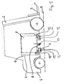
- FIG. 1 shows a side view of a forklift according to the invention.
- the load-bearing element of the forklift is a vehicle frame 1.
- a mast 2 is mounted with a load-receiving means 3 movable up and down.
- a tail weight 4 is movable up and down.
- the battery block 5 rests on a footprint 8, which according to the invention can be moved out of the battery compartment 7 in the lateral direction by means of a telescopic guide 6.
- the guide 6 comprises a basic element 10 connected to the vehicle frame 1, in which a first telescopic element 11 is displaceably guided.
- a second telescopic element 12, in turn, is displaceably guided in the first telescopic element 11.
- the second telescopic element 12 forms with the footprint 8 a common component.
- an extendable support 13 is attached directly on the second telescopic element 12 -.
- the support 13 is retracted and located within the vehicle contour.
- the support 13 automatically extends and supports the weight of the battery pack 5 directly on the roadway 9.
- a roller which rolls on the roadway 9 during the extension movement of the second telescopic element 12.
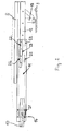
- the guide 6 of the fully extended footprint 8 is shown in side view.
- the primitive 10, which is not shown in its full length, is at the left end of the illustration.
- the base member 10 is not movable on the vehicle frame (Fig. 1, Pos. 1) attached.
- a first sliding element 21 the first telescopic element 11 is guided on the base element 10.
- the first sliding member 21 is attached to the first telescopic member 11 and can be moved relative to the base member 10 according to the left and right in the drawing.
- the first sliding element 21 allows a pivoting movement of the first telescopic element 11 about an axis 14 oriented perpendicular to the plane of the drawing.
- the second telescopic element 12 is guided displaceably on the first telescopic element 11 by means of the second sliding element 22.
- the two left in the drawing parts of the sliding member 22 are fixed to the second telescopic member 12, while the two right in the drawing parts of the sliding member 22 are attached to the first telescopic member 11.
- the second sliding element 22 allows a translatory sliding movement of the second telescopic element 12 relative to the first telescopic element 11, but no rotational movement.
- the support 13 which is fixed to the second telescopic element 12 and this is supported on the roadway 9. Shown is the support 13 in the extended position in which it prevents tilting of the extended telescopic elements 11, 12 about the axis 14. The support 13 then also carries at least part of the weight of a battery located on the footprint 8 battery block. A support element 23, also shown, is without function when the guide 6 is extended.
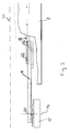
- FIG 3 the arrangement of Figure 2 is shown in plan view.
- a symmetry line 30 illustrates the axisymmetric design of the arrangement.
- the base element 10 the first telescopic element 11 and the second telescopic element 12 is shown.
- the first sliding member 21 with the rotational degree of freedom about the axis 14, and the two parts of the second sliding member 22nd
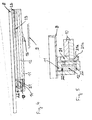
- Figure 4 shows the guide 6 for the footprint 8 - in a side view according to Figure 2 - in the inserted position, in which the footprint 8 is completely within the battery compartment (Fig. 1, Pos. 7).
- the basic element 10 the first telescopic element 11 and the second telescopic element 12, which are all pushed together.
- the first sliding element 21 the two parts of the second sliding element 22 and the support element 23, which is fastened to the first telescopic element 11.
- the support element 23 supports the first telescopic element 11 on the base element 10, so that the first telescopic element 11 does not tilt about the axis 14.
- the support 13 is retracted with the guide 6 inserted and does not absorb any forces.
- FIG. 5 shows a cross section through the guide 6, whereby only one half of the symmetrical arrangement is shown, as in FIG.
- the basic element 10, the first telescopic element 11, the second telescopic element 12 and the contact surface 8 can be seen.
- the first sliding element 21 enables a translatory displacement on a sliding surface 21 a and a rotational movement on a sliding surface 21 b.
- the second sliding element 22 is located between the first telescopic element 11 and the second telescopic element 12 and allows only a translatory relative movement.
Landscapes
- Engineering & Computer Science (AREA)
- Transportation (AREA)
- Mechanical Engineering (AREA)
- Chemical & Material Sciences (AREA)
- Combustion & Propulsion (AREA)
- Power Engineering (AREA)
- Structural Engineering (AREA)
- Civil Engineering (AREA)
- Life Sciences & Earth Sciences (AREA)
- Geology (AREA)
- Forklifts And Lifting Vehicles (AREA)
Abstract
Description
- Die Erfindung betrifft einen Gabelstapler mit einem Fahrzeugrahmen, der eine seitliche Entnahmeöffnung für einen Batterieblock aufweist, wobei für den Batterieblock eine Aufstandsfläche vorgesehen ist, welche mittels einer Führung zwischen einer Betriebsposition, in der sich die Aufstandsfläche vollständig innerhalb des Fahrzeugrahmens befindet, und einer Batteriewechselposition, in der sich die Aufstandsfläche vollständig außerhalb des Fahrzeugrahmens befindet, bewegbar ist.
- Gabelstapler, insbesondere Gegengewichtsgabelstapler, sind insbesondere in jüngerer Zeit häufig mit einer seitlichen Batterieentnahmeöffnung ausgeführt. Um den Batterieblock zu wechseln, wird der im Gabelstapler vorhandene Batterieblock in horizontaler Richtung aus dem Batteriefach des Gabelstaplers heraus bewegt. Dies kann beispielsweise mittels eines Gabelhubwagens geschehen, mit dem der im Gabelstapler befindliche Batterieblock unterfahren, geringfügig angehoben und dann aus dem Batteriefach heraus gefahren wird.
- Gleichermaßen üblich ist es bei den Betreibern von Gabelstaplern, die Batterieblöcke mittels eines Krans zu transportieren. Um dies bei Gabelstaplern mit einer seitlichen Batterieentnahmeöffnung zu ermöglichen, muss der Batterieblock zunächst vollständig aus dem Batteriefach heraus bewegt werden. Erst dann kann der Batterieblock an den Kran angehängt und angehoben werden. Analog hierzu kann während des Einsetzens in das Batteriefach der Batterieblock mittels des Krans nur neben die Entnahmeöffnung bewegt werden. Um den Batterieblock dann in horizontaler Richtung durch die Entnahmeöffnung in das Batteriefach zu bewegen, bedarf es einer Hilfsvorrichtung.
- Hilfsvorrichtungen, die es erlauben, den Batterieblock ohne Zuhilfenahme eines Gabelhubwagens in horizontaler Richtung in das Batteriefach hinein oder aus dem Batteriefach heraus zu bewegen, sind im Stand der Technik bereits bekannt. In der
DE 102 40 854 A1 ist beispielsweise beschrieben, unten im Batteriefach eine ausziehbare Rollenbahn anzuordnen. Nach dem Ausziehen der Rollenbahn kann der Batterieblock auf der Rollenbahn vollständig aus dem Batteriefach heraus gerollt werden. - Die bekannten, in den Gabelstapler integrierten Hilfsvorrichtungen erfordern in der Herstellung einen großen Bauaufwand und beanspruchen viel Bauraum innerhalb des Batteriefachs.
- Der vorliegenden Erfindung liegt die Aufgabe zugrunde, einen Gabelstapler mit einer einfach aufgebaute Hilfsvorrichtung zur horizontalen Batterieentnahme zur Verfügung zu stellen, die innerhalb des Gabelstaplers wenig Bauraum beansprucht.
- Diese Aufgabe wird erfindungsgemäß dadurch gelöst, dass die Führung als teleskopische Gleitführung ausgebildet ist, wobei ein Grundelement der Führung starr mit dem Fahrzeugrahmen verbunden ist, ein erstes Teleskopelement an dem Grundelement mittels eines ersten Gleitelements bewegbar geführt ist und ein zweites Teleskopelement an dem ersten Teleskopelement mittels eines zweiten Gleitelements bewegbar geführt ist und die Aufstandsfläche an dem zweiten Teleskopelement befestigt ist. Die teleskopische Ausführung der Führung mit zwei Teleskopelementen gewährleistet die erforderliche Ausfahrlänge der Führung, um den Batterieblock zwischen einer Position, in der er sich vollständig innerhalb des Gabelstaplers befindet und einer weiteren Position, in der er sich vollständig außerhalb des Gabelstaplers befindet, bewegen zu können. Das Grundelement, das erste Teleskopelement und das zweite Teleskopelement können jeweils ein- oder mehrteilig ausgeführt sein, wobei insbesondere mehrere Teile, die in Längsrichtung des Gabelstaplers voneinander beabstandet sind und in der Regel immer synchron bewegt werden, als zusammengehörend angesehen werden. Gleiches gilt für die Gleitelemente, wobei jedes Gleitelement in der Regel immer aus mehreren in Längsrichtung des Gabelstaplers versetzen Teilen besteht. Darüber hinaus kann jedes Gleitelement auch aus mehreren in Querrichtung des Gabelstaplers versetzten Teilen bestehen, die bei einer Ausfahrbewegung der Teleskopelemente relativ zueinander bewegt werden.
- Mit besonderem Vorteil ermöglicht das erste Gleitelement eine im Wesentlichen horizontale Linearbewegung des ersten Teleskopelements und eine Schwenkbewegung des ersten Teleskopelements um eine im Wesentlichen horizontale Achse. Die im Wesentlichen horizontale Linearbewegung erfolgt in Querrichtung des Gabelstaplers und entspricht der Ausfahr- bzw. Einfahrbewegung des Teleskopelements. Die darüber hinaus durch das erste Gleitelement ermöglichte Schwenkbewegung erlaubt ein zumindest geringfügiges Neigen des Teleskopelements nach oben oder nach unten. Dies ermöglicht einen Winkelausgleich, insbesondere in den Fällen, wenn die Fahrbahn unter dem Gabelstapler und/oder unter der Rollenbahn nicht eben oder nicht waagrecht ist.
- Das erste Gleitelement ist an dem - bei vollständig eingeschobener Aufstandsfläche von der Entnahmeöffnung aus betrachtet - hinteren Ende des ersten Teleskopelements befestigt. Das erste Gleitelement ist relativ zum ersten Teleskopelement nicht beweglich. Bei einem Aus- und Einfahren des ersten Teleskopelements wird das erste Gleitelement relativ zum Grundelement verschoben.
- Weiter ist ein Abstützelement vorgesehen, das an dem ersten Teleskopelement angeordnet ist und mit dem ein Teil der Gewichtskraft des Batterieblocks an dem Grundelement abstützbar ist. Bei vollständig eingeschobener Aufstandsfläche wird die Gewichtskraft des Batterieblocks über das erste Gleitelement und über das Abstützelement auf dem Grundelement abgestützt. Nach einem Ausziehen des ersten Teleskopelements befindet sich das Abstützelement nicht mehr über dem Grundelement und hat in dieser Stellung dann keine Funktion.
- Das Abstützelement ist an dem - bei vollständig eingeschobener Aufstandsfläche von der Entnahmeöffnung aus betrachtet - vorderen Ende des ersten Teleskopelements befestigt.
- Um bei ausgefahrener Aufstandsfläche ein Kippen des Gabelstaplers oder ein Abknicken der teleskopischen Gleitführung zu vermeiden, ist eine ausfahrbare Stütze vorgesehenen, die an dem zweiten Teleskopelement angeordnet ist und mit der ein Teil der Gewichtskraft des Batterieblocks an einer Fahrbahn abstützbar ist. Die Stütze ist an dem zweiten Teleskopelement befestigt. Bei eingeschobener Aufstandsfläche ist die Stütze eingefahren und befindet sich innerhalb des Batteriefachs. Während der Ausfahrbewegung der Aufstandsfläche wird die Stütze nach unten ausgefahren, sobald sie sich vollständig außerhalb des Gabelstaplers befindet. Die ausgefahrene Stütze stützt das zweite Teleskopelement an der Fahrbahn ab und nimmt dabei zumindest einen Teil der Gewichtskraft des Batterieblocks auf.
- Das zweite Gleitelement ermöglicht ausschließlich eine im Wesentlichen horizontale Linearbewegung des zweiten Teleskopelements relativ zum ersten Teleskopelement.
- Eine Rotationsbewegung der beiden Teleskopelemente relativ zueinander ist damit verhindert.
- Weitere Vorteile und Einzelheiten der Erfindung werden anhand des in den schematischen Figuren dargestellten Ausführungsbeispiels näher erläutert. Dabei zeigt
- Figur 1
- einen erfindungsgemäßen Gabelstapler in Seitenansicht,
- Figur 2
- die Führung für die Aufstandsfläche in ausgezogener Stellung,
- Figur 3
- die Anordnung gemäß Fig. 2 in Draufsicht,
- Figur 4
- die Führung für die Aufstandsfläche in eingeschobener Stellung,
- Figur 5
- einen Querschnitt durch die Führung.
- Figur 1 zeigt einen erfindungsgemäßen Gabelstapler in Seitenansicht. Das tragende Element des Gabelstaplers ist ein Fahrzeugrahmen 1. Vorne am Gabelstapler ist ein Hubgerüst 2 mit einem nach oben und unten bewegbaren Lastaufnahmemittel 3 befestigt. Am hinteren Ende des Gabelstaplers befindet sich ein Heckgewicht 4.
- In einem Freiraum des Fahrzeugrahmens befindet sich ein seitlich offenes Batteriefach 7, in dem ein Batterieblock 5 angeordnet ist. Der Batterieblock 5 steht auf einer Aufstandsfläche 8 auf, welche erfindungsgemäß mittels einer teleskopischen Führung 6 in seitlicher Richtung aus dem Batteriefach 7 heraus bewegt werden kann. Die Führung 6 umfasst ein mit dem Fahrzeugrahmen 1 verbundenes Grundelement 10, in dem ein erstes Teleskopelement 11 verschiebbar geführt ist. Ein zweites Teleskopelement 12 wiederum ist in dem ersten Teleskopelement 11 verschiebbar geführt. Das zweite Teleskopelement 12 bildet mit der Aufstandsfläche 8 ein gemeinsames Bauteil.
- An der Aufstandsfläche 8 - oder in einer anderen möglichen Ausführungsform direkt an dem zweiten Teleskopelement 12 - ist eine ausfahrbare Stütze 13 befestigt. Solange sich die Aufstandsfläche 8 innerhalb des Fahrzeugrahmens 1 befindet, ist die Stütze 13 eingefahren und befindet sich innerhalb der Fahrzeugkontur. Sobald sich die Stütze 13 außerhalb des Fahrzeugrahmens 1 befindet, fährt sie automatisch aus und stützt die Gewichtskraft des Batterieblocks 5 direkt an der Fahrbahn 9 ab. Am unteren Ende der Stütze 13 befindet sich eine Rolle, die während der Ausfahrbewegung des zweiten Teleskopelements 12 auf der Fahrbahn 9 abrollt.
- In Figur 2 ist die Führung 6 der vollständig ausgezogenen Aufstandsfläche 8 in Seitenansicht dargestellt. Das Grundelement 10, das nicht in seiner vollständigen Länge dargestellt ist, befindet sich am linken Ende der Darstellung. Das Grundelement 10 ist nicht bewegbar am Fahrzeugrahmen (Fig. 1, Pos. 1) befestigt. Mittels eines ersten Gleitelements 21 ist das erste Teleskopelement 11 an dem Grundelement 10 geführt. Dabei ist das erste Gleitelement 21 an dem ersten Teleskopelement 11 befestigt und kann relativ zu dem Grundelement 10 nach in der Zeichnung links und rechts verschoben werden. Zusätzlich ermöglicht das erste Gleitelement 21 eine Schwenkbewegung des ersten Teleskopelements 11 um eine senkrecht zur Zeichenebene ausgerichtete Achse 14.
- Das zweite Teleskopelement 12 ist an dem ersten Teleskopelement 11 mittels des zweiten Gleitelements 22 verschiebbar geführt. Hierbei sind die beiden in der Zeichnung linken Teile des Gleitelements 22 an dem zweiten Teleskopelement 12 befestigt, während die beiden in der Zeichnung rechten Teile des Gleitelements 22 an dem ersten Teleskopelement 11 befestigt sind. Das zweite Gleitelement 22 ermöglicht eine translatorische Schiebebewegung des zweiten Teleskopelements 12 relativ zum ersten Teleskopelement 11, jedoch keine Rotationsbewegung.
- Weiter zu erkennen ist die Stütze 13, die an dem zweiten Teleskopelement 12 befestigt ist und dieses an der Fahrbahn 9 abstützt. Dargestellt ist die Stütze 13 in ausgefahrener Stellung, in der sie ein Abkippen der ausgefahrenen Teleskopelemente 11, 12 um die Achse 14 verhindert. Die Stütze 13 trägt dann auch zumindest einen Teil der Gewichtskraft eines auf der Aufstandsfläche 8 befindlichen Batterieblocks. Ein ebenfalls dargestelltes Abstützelement 23 ist bei ausgezogener Führung 6 ohne Funktion.
- In Figur 3 ist die Anordnung gemäß Figur 2 in Draufsicht dargestellt. Eine Symmetrielinie 30 verdeutlicht die achsensymmetrische Ausbildung der Anordnung. Der Einfachheit halber ist jedoch von dem Grundelement 10, dem ersten Teleskopelement 11 und dem zweiten Teleskopelement 12 jeweils nur eine Hälfte dargestellt. Zu erkennen sind ebenfalls das erste Gleitelement 21 mit dem rotatorischen Freiheitsgrad um die Achse 14, sowie die beiden Teile des zweiten Gleitelements 22.
- Figur 4 zeigt die Führung 6 für die Aufstandsfläche 8 - in einer Seitenansicht entsprechend Figur 2 - in eingeschobener Stellung, bei der sich die Aufstandsfläche 8 vollständig innerhalb des Batteriefachs (Fig. 1, Pos. 7) befindet. Zu erkennen sind das Grundelement 10; das erste Teleskopelement 11 sowie das zweite Teleskopelement 12, die alle ineinander geschoben sind. Ebenso zu erkennen sind das erste Gleitelement 21, die beiden Teile des zweiten Gleitelements 22 sowie das Abstützelement 23, welches an dem ersten Teleskopelement 11 befestigt ist. Das Abstützelement 23 stützt bei eingeschobener Führung 6 das erste Teleskopelement 11 an dem Grundelement 10 ab, sodass das erste Teleskopelement 11 nicht um die Achse 14 abkippt. Die Stütze 13 ist bei eingeschobener Führung 6 eingefahren und nimmt keine Kräfte auf.
- In Figur 5 ist ein Querschnitt durch die Führung 6 dargestellt, wobei wie in Fig. 3 nur eine Hälfte der symmetrischen Anordnung dargestellt ist. Zu erkennen sind das Grundelement 10, das erste Teleskopelement 11, das zweite Teleskopelement 12 und die Aufstandsfläche 8. Das erste Gleitelement 21 ermöglicht an einer Gleitfläche 21 a eine translatorische Verschiebung und an einer Gleitfläche 21 b eine rotatorische Bewegung. Das zweite Gleitelement 22 befindet sich zwischen dem ersten Teleskopelement 11 und dem zweiten Teleskopelement 12 und ermöglicht ausschließlich eine translatorische Relativbewegung.
Claims (7)
- Gabelstapler mit einem Fahrzeugrahmen (1), der eine seitliche Entnahmeöffnung für einen Batterieblock (5) aufweist, wobei für den Batterieblock (5) eine Aufstandsfläche (8) vorgesehen ist, welche mittels einer Führung (6) zwischen einer Betriebsposition, in der sich die Aufstandsfläche (8) vollständig innerhalb des Fahrzeugrahmens (1) befindet, und einer Batteriewechselposition, in der sich die Aufstandsfläche (8) vollständig außerhalb des Fahrzeugrahmens (1) befindet, bewegbar ist, dadurch gekennzeichnet, dass die Führung (6) als teleskopische Gleitführung ausgebildet ist; wobei ein Grundelement (10) der Führung (6) starr mit dem Fahrzeugrahmen (1) verbunden ist, ein erstes Teleskopelement (11) an dem Grundelement (10) mittels eines ersten Gleitelements (21) bewegbar geführt ist und ein zweites Teleskopelement (12) an dem ersten Teleskopelement (11) mittels eines zweiten Gleitelements (22) bewegbar geführt ist und die Aufstandsfläche (8) an dem zweiten Teleskopelement (12) befestigt ist.
- Gabelstapler nach Anspruch 1, dadurch gekennzeichnet, dass das erste Gleitelement (21) eine im Wesentlichen horizontale Linearbewegung des ersten Teleskopelements (11) und eine Schwenkbewegung des ersten Teleskopelements (11) um eine im Wesentlichen horizontale Achse (14) ermöglicht.
- Gabelstapler nach Anspruch 1 oder 2, dadurch gekennzeichnet, dass das erste Gleitelement (21) an dem - bei vollständig eingeschobener Aufstandsfläche (8) von der Entnahmeöffnung aus betrachtet - hinteren Ende des ersten Teleskopelements (11) befestigt ist.
- Gabelstapler nach einem der Ansprüche 1 bis 3, dadurch gekennzeichnet, dass ein Abstützelement (23) vorgesehen ist, das an dem ersten Teleskopelement (11) angeordnet ist und mit dem ein Teil der Gewichtskraft des Batterieblocks (5) an dem Grundelement (10) abstützbar ist.
- Gabelstapler nach Anspruch 4, dadurch gekennzeichnet, dass das Abstützelement (23) an dem - bei vollständig eingeschobener Aufstandsfläche (8) von der Entnahmeöffnung aus betrachtet - vorderen Ende des ersten Teleskopelements (11) befestigt ist.
- Gabelstapler nach einem der Ansprüche 1 bis 5, dadurch gekennzeichnet, dass eine ausfahrbare Stütze (13) vorgesehenen ist, die an dem zweiten Teleskopelement (12) angeordnet ist und mit der ein Teil der Gewichtskraft des Batterieblocks (5) an einer Fahrbahn (9) abstützbar ist.
- Gabelstapler nach einem der Ansprüche 1 bis 6, dadurch gekennzeichnet, dass das zweite Gleitelement (22) ausschließlich eine im Wesentlichen horizontale Linearbewegung des zweiten Teleskopelements (12) relativ zum ersten Teleskopelement (11) ermöglicht.
Applications Claiming Priority (1)
| Application Number | Priority Date | Filing Date | Title |
|---|---|---|---|
| DE102006055363A DE102006055363A1 (de) | 2006-11-23 | 2006-11-23 | Gabelstapler mit einer Führung zum seitlichen Ausziehen eines Batterieblocks |
Publications (4)
| Publication Number | Publication Date |
|---|---|
| EP1925588A2 true EP1925588A2 (de) | 2008-05-28 |
| EP1925588A3 EP1925588A3 (de) | 2009-09-23 |
| EP1925588B1 EP1925588B1 (de) | 2011-01-19 |
| EP1925588B9 EP1925588B9 (de) | 2011-03-23 |
Family
ID=39047759
Family Applications (1)
| Application Number | Title | Priority Date | Filing Date |
|---|---|---|---|
| EP07021206A Not-in-force EP1925588B9 (de) | 2006-11-23 | 2007-10-30 | Gabelstapler mit einer Führung zum seitlichen Ausziehen eines Batterieblocks |
Country Status (3)
| Country | Link |
|---|---|
| EP (1) | EP1925588B9 (de) |
| AT (1) | ATE495999T1 (de) |
| DE (2) | DE102006055363A1 (de) |
Cited By (6)
| Publication number | Priority date | Publication date | Assignee | Title |
|---|---|---|---|---|
| EP2011761A3 (de) * | 2007-07-05 | 2009-01-21 | Jungheinrich Aktiengesellschaft | Flurförderzeug, insbesondere Gabelstapler |
| EP2287041A1 (de) * | 2009-08-21 | 2011-02-23 | Fahrzeugwerk Bernard Krone GmbH | Fahrzeugaufbau |
| CN102139622A (zh) * | 2011-03-01 | 2011-08-03 | 湖南南车时代电动汽车股份有限公司 | 一种电动汽车蓄电池安装方法及装置 |
| CN103192805A (zh) * | 2013-04-10 | 2013-07-10 | 科朗设备(苏州)有限公司 | 一种电动叉车蓄电池辅助更换装置 |
| EP3608990A1 (de) * | 2018-08-08 | 2020-02-12 | The Raymond Corporation | Systeme und verfahren für ein modulares batteriesystem |
| EP3719862A1 (de) * | 2019-04-03 | 2020-10-07 | The Raymond Corporation | Systeme und verfahren für ein modulares batteriesystem |
Families Citing this family (1)
| Publication number | Priority date | Publication date | Assignee | Title |
|---|---|---|---|---|
| CN114715081B (zh) * | 2018-07-20 | 2023-06-23 | 奥动新能源汽车科技有限公司 | 换电控制系统及方法 |
Citations (1)
| Publication number | Priority date | Publication date | Assignee | Title |
|---|---|---|---|---|
| EP1661847A1 (de) | 2004-11-24 | 2006-05-31 | Still Gmbh | Flurförderzeug mit einer bewegbaren Aufstandsfläche für einen Batterieblock |
Family Cites Families (1)
| Publication number | Priority date | Publication date | Assignee | Title |
|---|---|---|---|---|
| DE102005022094A1 (de) * | 2005-05-12 | 2006-11-16 | Still Gmbh | Flurförderzeug mit einem seitlich ausziehbaren Batterieblock |
-
2006
- 2006-11-23 DE DE102006055363A patent/DE102006055363A1/de not_active Withdrawn
-
2007
- 2007-10-30 EP EP07021206A patent/EP1925588B9/de not_active Not-in-force
- 2007-10-30 AT AT07021206T patent/ATE495999T1/de active
- 2007-10-30 DE DE502007006300T patent/DE502007006300D1/de active Active
Patent Citations (1)
| Publication number | Priority date | Publication date | Assignee | Title |
|---|---|---|---|---|
| EP1661847A1 (de) | 2004-11-24 | 2006-05-31 | Still Gmbh | Flurförderzeug mit einer bewegbaren Aufstandsfläche für einen Batterieblock |
Cited By (16)
| Publication number | Priority date | Publication date | Assignee | Title |
|---|---|---|---|---|
| EP2011761A3 (de) * | 2007-07-05 | 2009-01-21 | Jungheinrich Aktiengesellschaft | Flurförderzeug, insbesondere Gabelstapler |
| US8191688B2 (en) | 2007-07-05 | 2012-06-05 | Jungheinrich Aktiengesellschaft | Industrial truck with exchangeable battery block |
| EP2287041A1 (de) * | 2009-08-21 | 2011-02-23 | Fahrzeugwerk Bernard Krone GmbH | Fahrzeugaufbau |
| CN102139622A (zh) * | 2011-03-01 | 2011-08-03 | 湖南南车时代电动汽车股份有限公司 | 一种电动汽车蓄电池安装方法及装置 |
| CN102139622B (zh) * | 2011-03-01 | 2015-05-06 | 湖南南车时代电动汽车股份有限公司 | 一种电动汽车蓄电池安装方法及装置 |
| CN103192805A (zh) * | 2013-04-10 | 2013-07-10 | 科朗设备(苏州)有限公司 | 一种电动叉车蓄电池辅助更换装置 |
| CN103192805B (zh) * | 2013-04-10 | 2015-06-17 | 科朗设备(苏州)有限公司 | 一种电动叉车蓄电池辅助更换装置 |
| CN110834527A (zh) * | 2018-08-08 | 2020-02-25 | 雷蒙德股份有限公司 | 用于模块化电池系统的系统和方法 |
| EP3608990A1 (de) * | 2018-08-08 | 2020-02-12 | The Raymond Corporation | Systeme und verfahren für ein modulares batteriesystem |
| US11065967B2 (en) | 2018-08-08 | 2021-07-20 | The Raymond Corporation | Systems and methods for a modular battery system |
| CN110834527B (zh) * | 2018-08-08 | 2024-08-20 | 雷蒙德股份有限公司 | 用于模块化电池系统的系统和方法 |
| EP3719862A1 (de) * | 2019-04-03 | 2020-10-07 | The Raymond Corporation | Systeme und verfahren für ein modulares batteriesystem |
| CN111799407A (zh) * | 2019-04-03 | 2020-10-20 | 雷蒙德股份有限公司 | 用于模块化电池系统的系统和方法 |
| US11233291B2 (en) * | 2019-04-03 | 2022-01-25 | The Raymond Corporation | Systems and methods for a modular battery system |
| CN111799407B (zh) * | 2019-04-03 | 2024-06-14 | 雷蒙德股份有限公司 | 用于模块化电池系统的系统和方法 |
| AU2020202104B2 (en) * | 2019-04-03 | 2025-08-21 | The Raymond Corporation | Systems and methods for a modular battery system |
Also Published As
| Publication number | Publication date |
|---|---|
| EP1925588A3 (de) | 2009-09-23 |
| DE502007006300D1 (de) | 2011-03-03 |
| EP1925588B1 (de) | 2011-01-19 |
| DE102006055363A1 (de) | 2008-06-26 |
| ATE495999T1 (de) | 2011-02-15 |
| EP1925588B9 (de) | 2011-03-23 |
Similar Documents
| Publication | Publication Date | Title |
|---|---|---|
| EP3013729B1 (de) | Hebevorrichtung für fahrzeuge | |
| EP0983897B1 (de) | Hebevorrichtung | |
| EP1925588B1 (de) | Gabelstapler mit einer Führung zum seitlichen Ausziehen eines Batterieblocks | |
| EP1935731B1 (de) | Gabelstapler mit einer Führung zur seitlichen Batterieentnahme | |
| EP1925512B1 (de) | Flurförderzeug mit seitlich entnehmbarer Batterie | |
| EP1415874B1 (de) | Batteriewechselsystem für ein Flurförderzeug | |
| EP1396466B1 (de) | Flurförderzeug mit einer seitlichen Batterieentnahmeöffnung | |
| EP3609833B1 (de) | Hebebühne zum anheben von fahrzeugen | |
| EP2248758B1 (de) | Flurförderzeug, insbesondere Gegengewichtsgabelstapler | |
| EP2953887B1 (de) | Vorrichtung zur aufnahme und zum transport von lasten | |
| EP1849535A1 (de) | Walzgerüst | |
| EP1661847B1 (de) | Flurförderzeug mit einer bewegbaren Aufstandsfläche für einen Batterieblock | |
| EP1690823B1 (de) | Flurförderzeug | |
| DE102005022094A1 (de) | Flurförderzeug mit einem seitlich ausziehbaren Batterieblock | |
| EP2248702B1 (de) | Hubvorrichtung | |
| DE102015122455A1 (de) | Flurförderzeug | |
| EP3120969B1 (de) | Mobile achsenpresse | |
| EP1481941B1 (de) | Flurförderzeug mit einer Schienenführung | |
| EP1780170B1 (de) | Flutförderzeug mit einer bewegbaren Aufstandsfläche für einen Batterieblock | |
| DE102004052066A1 (de) | Hubgerüst für ein Flurförderzeug | |
| EP1122207B1 (de) | Schwenkschubgabel | |
| EP2072453B1 (de) | Abstützvorrichtung | |
| EP3463975A1 (de) | Abschiebevorrichtung und abschiebewagen mit einer abschiebevorrichtung | |
| DE10321487A1 (de) | Schubmaststapler |
Legal Events
| Date | Code | Title | Description |
|---|---|---|---|
| PUAI | Public reference made under article 153(3) epc to a published international application that has entered the european phase |
Free format text: ORIGINAL CODE: 0009012 |
|
| AK | Designated contracting states |
Kind code of ref document: A2 Designated state(s): AT BE BG CH CY CZ DE DK EE ES FI FR GB GR HU IE IS IT LI LT LU LV MC MT NL PL PT RO SE SI SK TR |
|
| AX | Request for extension of the european patent |
Extension state: AL BA HR MK RS |
|
| RIN1 | Information on inventor provided before grant (corrected) |
Inventor name: EVERT, RAINER Inventor name: BAVENDIEK, RAINER, DR. Inventor name: BERGMANN, ANSGAR Inventor name: LUNDELIUS, JENS Inventor name: STRUGG, GERALD. |
|
| PUAL | Search report despatched |
Free format text: ORIGINAL CODE: 0009013 |
|
| AK | Designated contracting states |
Kind code of ref document: A3 Designated state(s): AT BE BG CH CY CZ DE DK EE ES FI FR GB GR HU IE IS IT LI LT LU LV MC MT NL PL PT RO SE SI SK TR |
|
| AX | Request for extension of the european patent |
Extension state: AL BA HR MK RS |
|
| 17P | Request for examination filed |
Effective date: 20100107 |
|
| 17Q | First examination report despatched |
Effective date: 20100209 |
|
| AKX | Designation fees paid |
Designated state(s): AT BE BG CH CY CZ DE DK EE ES FI FR GB GR HU IE IS IT LI LT LU LV MC MT NL PL PT RO SE SI SK TR |
|
| GRAP | Despatch of communication of intention to grant a patent |
Free format text: ORIGINAL CODE: EPIDOSNIGR1 |
|
| GRAS | Grant fee paid |
Free format text: ORIGINAL CODE: EPIDOSNIGR3 |
|
| GRAA | (expected) grant |
Free format text: ORIGINAL CODE: 0009210 |
|
| AK | Designated contracting states |
Kind code of ref document: B1 Designated state(s): AT BE BG CH CY CZ DE DK EE ES FI FR GB GR HU IE IS IT LI LT LU LV MC MT NL PL PT RO SE SI SK TR |
|
| REG | Reference to a national code |
Ref country code: GB Ref legal event code: FG4D Free format text: NOT ENGLISH |
|
| REG | Reference to a national code |
Ref country code: CH Ref legal event code: EP |
|
| REG | Reference to a national code |
Ref country code: IE Ref legal event code: FG4D Free format text: LANGUAGE OF EP DOCUMENT: GERMAN |
|
| REF | Corresponds to: |
Ref document number: 502007006300 Country of ref document: DE Date of ref document: 20110303 Kind code of ref document: P |
|
| REG | Reference to a national code |
Ref country code: DE Ref legal event code: R096 Ref document number: 502007006300 Country of ref document: DE Effective date: 20110303 |
|
| REG | Reference to a national code |
Ref country code: NL Ref legal event code: VDEP Effective date: 20110119 |
|
| LTIE | Lt: invalidation of european patent or patent extension |
Effective date: 20110119 |
|
| PG25 | Lapsed in a contracting state [announced via postgrant information from national office to epo] |
Ref country code: LV Free format text: LAPSE BECAUSE OF FAILURE TO SUBMIT A TRANSLATION OF THE DESCRIPTION OR TO PAY THE FEE WITHIN THE PRESCRIBED TIME-LIMIT Effective date: 20110119 Ref country code: PT Free format text: LAPSE BECAUSE OF FAILURE TO SUBMIT A TRANSLATION OF THE DESCRIPTION OR TO PAY THE FEE WITHIN THE PRESCRIBED TIME-LIMIT Effective date: 20110519 Ref country code: ES Free format text: LAPSE BECAUSE OF FAILURE TO SUBMIT A TRANSLATION OF THE DESCRIPTION OR TO PAY THE FEE WITHIN THE PRESCRIBED TIME-LIMIT Effective date: 20110430 Ref country code: IS Free format text: LAPSE BECAUSE OF FAILURE TO SUBMIT A TRANSLATION OF THE DESCRIPTION OR TO PAY THE FEE WITHIN THE PRESCRIBED TIME-LIMIT Effective date: 20110519 Ref country code: LT Free format text: LAPSE BECAUSE OF FAILURE TO SUBMIT A TRANSLATION OF THE DESCRIPTION OR TO PAY THE FEE WITHIN THE PRESCRIBED TIME-LIMIT Effective date: 20110119 Ref country code: SE Free format text: LAPSE BECAUSE OF FAILURE TO SUBMIT A TRANSLATION OF THE DESCRIPTION OR TO PAY THE FEE WITHIN THE PRESCRIBED TIME-LIMIT Effective date: 20110119 Ref country code: GR Free format text: LAPSE BECAUSE OF FAILURE TO SUBMIT A TRANSLATION OF THE DESCRIPTION OR TO PAY THE FEE WITHIN THE PRESCRIBED TIME-LIMIT Effective date: 20110420 |
|
| REG | Reference to a national code |
Ref country code: IE Ref legal event code: FD4D |
|
| PG25 | Lapsed in a contracting state [announced via postgrant information from national office to epo] |
Ref country code: NL Free format text: LAPSE BECAUSE OF FAILURE TO SUBMIT A TRANSLATION OF THE DESCRIPTION OR TO PAY THE FEE WITHIN THE PRESCRIBED TIME-LIMIT Effective date: 20110119 Ref country code: FI Free format text: LAPSE BECAUSE OF FAILURE TO SUBMIT A TRANSLATION OF THE DESCRIPTION OR TO PAY THE FEE WITHIN THE PRESCRIBED TIME-LIMIT Effective date: 20110119 Ref country code: SI Free format text: LAPSE BECAUSE OF FAILURE TO SUBMIT A TRANSLATION OF THE DESCRIPTION OR TO PAY THE FEE WITHIN THE PRESCRIBED TIME-LIMIT Effective date: 20110119 Ref country code: BG Free format text: LAPSE BECAUSE OF FAILURE TO SUBMIT A TRANSLATION OF THE DESCRIPTION OR TO PAY THE FEE WITHIN THE PRESCRIBED TIME-LIMIT Effective date: 20110419 Ref country code: CY Free format text: LAPSE BECAUSE OF FAILURE TO SUBMIT A TRANSLATION OF THE DESCRIPTION OR TO PAY THE FEE WITHIN THE PRESCRIBED TIME-LIMIT Effective date: 20110119 Ref country code: PL Free format text: LAPSE BECAUSE OF FAILURE TO SUBMIT A TRANSLATION OF THE DESCRIPTION OR TO PAY THE FEE WITHIN THE PRESCRIBED TIME-LIMIT Effective date: 20110119 |
|
| PG25 | Lapsed in a contracting state [announced via postgrant information from national office to epo] |
Ref country code: DK Free format text: LAPSE BECAUSE OF FAILURE TO SUBMIT A TRANSLATION OF THE DESCRIPTION OR TO PAY THE FEE WITHIN THE PRESCRIBED TIME-LIMIT Effective date: 20110119 Ref country code: IE Free format text: LAPSE BECAUSE OF FAILURE TO SUBMIT A TRANSLATION OF THE DESCRIPTION OR TO PAY THE FEE WITHIN THE PRESCRIBED TIME-LIMIT Effective date: 20110119 Ref country code: EE Free format text: LAPSE BECAUSE OF FAILURE TO SUBMIT A TRANSLATION OF THE DESCRIPTION OR TO PAY THE FEE WITHIN THE PRESCRIBED TIME-LIMIT Effective date: 20110119 |
|
| PLBE | No opposition filed within time limit |
Free format text: ORIGINAL CODE: 0009261 |
|
| STAA | Information on the status of an ep patent application or granted ep patent |
Free format text: STATUS: NO OPPOSITION FILED WITHIN TIME LIMIT |
|
| PG25 | Lapsed in a contracting state [announced via postgrant information from national office to epo] |
Ref country code: RO Free format text: LAPSE BECAUSE OF FAILURE TO SUBMIT A TRANSLATION OF THE DESCRIPTION OR TO PAY THE FEE WITHIN THE PRESCRIBED TIME-LIMIT Effective date: 20110119 Ref country code: SK Free format text: LAPSE BECAUSE OF FAILURE TO SUBMIT A TRANSLATION OF THE DESCRIPTION OR TO PAY THE FEE WITHIN THE PRESCRIBED TIME-LIMIT Effective date: 20110119 Ref country code: CZ Free format text: LAPSE BECAUSE OF FAILURE TO SUBMIT A TRANSLATION OF THE DESCRIPTION OR TO PAY THE FEE WITHIN THE PRESCRIBED TIME-LIMIT Effective date: 20110119 |
|
| 26N | No opposition filed |
Effective date: 20111020 |
|
| PG25 | Lapsed in a contracting state [announced via postgrant information from national office to epo] |
Ref country code: IT Free format text: LAPSE BECAUSE OF FAILURE TO SUBMIT A TRANSLATION OF THE DESCRIPTION OR TO PAY THE FEE WITHIN THE PRESCRIBED TIME-LIMIT Effective date: 20110119 |
|
| REG | Reference to a national code |
Ref country code: DE Ref legal event code: R097 Ref document number: 502007006300 Country of ref document: DE Effective date: 20111020 |
|
| BERE | Be: lapsed |
Owner name: STILL G.M.B.H. Effective date: 20111031 |
|
| PG25 | Lapsed in a contracting state [announced via postgrant information from national office to epo] |
Ref country code: MC Free format text: LAPSE BECAUSE OF NON-PAYMENT OF DUE FEES Effective date: 20111031 |
|
| REG | Reference to a national code |
Ref country code: CH Ref legal event code: PL |
|
| GBPC | Gb: european patent ceased through non-payment of renewal fee |
Effective date: 20111030 |
|
| REG | Reference to a national code |
Ref country code: FR Ref legal event code: ST Effective date: 20120629 |
|
| PG25 | Lapsed in a contracting state [announced via postgrant information from national office to epo] |
Ref country code: CH Free format text: LAPSE BECAUSE OF NON-PAYMENT OF DUE FEES Effective date: 20111031 Ref country code: LI Free format text: LAPSE BECAUSE OF NON-PAYMENT OF DUE FEES Effective date: 20111031 Ref country code: BE Free format text: LAPSE BECAUSE OF NON-PAYMENT OF DUE FEES Effective date: 20111031 |
|
| PG25 | Lapsed in a contracting state [announced via postgrant information from national office to epo] |
Ref country code: GB Free format text: LAPSE BECAUSE OF NON-PAYMENT OF DUE FEES Effective date: 20111030 Ref country code: FR Free format text: LAPSE BECAUSE OF NON-PAYMENT OF DUE FEES Effective date: 20111102 |
|
| PG25 | Lapsed in a contracting state [announced via postgrant information from national office to epo] |
Ref country code: MT Free format text: LAPSE BECAUSE OF FAILURE TO SUBMIT A TRANSLATION OF THE DESCRIPTION OR TO PAY THE FEE WITHIN THE PRESCRIBED TIME-LIMIT Effective date: 20110119 |
|
| PG25 | Lapsed in a contracting state [announced via postgrant information from national office to epo] |
Ref country code: LU Free format text: LAPSE BECAUSE OF NON-PAYMENT OF DUE FEES Effective date: 20111030 |
|
| PG25 | Lapsed in a contracting state [announced via postgrant information from national office to epo] |
Ref country code: TR Free format text: LAPSE BECAUSE OF FAILURE TO SUBMIT A TRANSLATION OF THE DESCRIPTION OR TO PAY THE FEE WITHIN THE PRESCRIBED TIME-LIMIT Effective date: 20110119 |
|
| PG25 | Lapsed in a contracting state [announced via postgrant information from national office to epo] |
Ref country code: HU Free format text: LAPSE BECAUSE OF FAILURE TO SUBMIT A TRANSLATION OF THE DESCRIPTION OR TO PAY THE FEE WITHIN THE PRESCRIBED TIME-LIMIT Effective date: 20110119 |
|
| REG | Reference to a national code |
Ref country code: AT Ref legal event code: MM01 Ref document number: 495999 Country of ref document: AT Kind code of ref document: T Effective date: 20121031 |
|
| PG25 | Lapsed in a contracting state [announced via postgrant information from national office to epo] |
Ref country code: AT Free format text: LAPSE BECAUSE OF NON-PAYMENT OF DUE FEES Effective date: 20121031 |
|
| PGFP | Annual fee paid to national office [announced via postgrant information from national office to epo] |
Ref country code: DE Payment date: 20231018 Year of fee payment: 17 |
|
| REG | Reference to a national code |
Ref country code: DE Ref legal event code: R119 Ref document number: 502007006300 Country of ref document: DE |
|
| PG25 | Lapsed in a contracting state [announced via postgrant information from national office to epo] |
Ref country code: DE Free format text: LAPSE BECAUSE OF NON-PAYMENT OF DUE FEES Effective date: 20250501 |