EP1925453B1 - Druckkopfbehälter - Google Patents
Druckkopfbehälter Download PDFInfo
- Publication number
- EP1925453B1 EP1925453B1 EP07121067.8A EP07121067A EP1925453B1 EP 1925453 B1 EP1925453 B1 EP 1925453B1 EP 07121067 A EP07121067 A EP 07121067A EP 1925453 B1 EP1925453 B1 EP 1925453B1
- Authority
- EP
- European Patent Office
- Prior art keywords
- reservoir
- filter
- ink
- chamber
- input
- Prior art date
- Legal status (The legal status is an assumption and is not a legal conclusion. Google has not performed a legal analysis and makes no representation as to the accuracy of the status listed.)
- Ceased
Links
- 239000012530 fluid Substances 0.000 claims description 21
- 229910001220 stainless steel Inorganic materials 0.000 claims description 3
- 239000010935 stainless steel Substances 0.000 claims description 3
- 239000000463 material Substances 0.000 description 7
- XAGFODPZIPBFFR-UHFFFAOYSA-N aluminium Chemical compound [Al] XAGFODPZIPBFFR-UHFFFAOYSA-N 0.000 description 3
- 229910052782 aluminium Inorganic materials 0.000 description 3
- 238000013459 approach Methods 0.000 description 3
- 230000000052 comparative effect Effects 0.000 description 3
- 239000000758 substrate Substances 0.000 description 3
- 239000003086 colorant Substances 0.000 description 2
- 239000007787 solid Substances 0.000 description 2
- 230000008878 coupling Effects 0.000 description 1
- 238000010168 coupling process Methods 0.000 description 1
- 238000005859 coupling reaction Methods 0.000 description 1
- 230000005574 cross-species transmission Effects 0.000 description 1
- 238000000034 method Methods 0.000 description 1
- 239000002245 particle Substances 0.000 description 1
- 230000001105 regulatory effect Effects 0.000 description 1
- 239000007921 spray Substances 0.000 description 1
- 238000011144 upstream manufacturing Methods 0.000 description 1
Images


Classifications
-
- B—PERFORMING OPERATIONS; TRANSPORTING
- B41—PRINTING; LINING MACHINES; TYPEWRITERS; STAMPS
- B41J—TYPEWRITERS; SELECTIVE PRINTING MECHANISMS, i.e. MECHANISMS PRINTING OTHERWISE THAN FROM A FORME; CORRECTION OF TYPOGRAPHICAL ERRORS
- B41J2/00—Typewriters or selective printing mechanisms characterised by the printing or marking process for which they are designed
- B41J2/005—Typewriters or selective printing mechanisms characterised by the printing or marking process for which they are designed characterised by bringing liquid or particles selectively into contact with a printing material
- B41J2/01—Ink jet
- B41J2/17—Ink jet characterised by ink handling
- B41J2/175—Ink supply systems ; Circuit parts therefor
- B41J2/17563—Ink filters
-
- B—PERFORMING OPERATIONS; TRANSPORTING
- B41—PRINTING; LINING MACHINES; TYPEWRITERS; STAMPS
- B41J—TYPEWRITERS; SELECTIVE PRINTING MECHANISMS, i.e. MECHANISMS PRINTING OTHERWISE THAN FROM A FORME; CORRECTION OF TYPOGRAPHICAL ERRORS
- B41J2/00—Typewriters or selective printing mechanisms characterised by the printing or marking process for which they are designed
- B41J2/005—Typewriters or selective printing mechanisms characterised by the printing or marking process for which they are designed characterised by bringing liquid or particles selectively into contact with a printing material
- B41J2/01—Ink jet
- B41J2/17—Ink jet characterised by ink handling
- B41J2/175—Ink supply systems ; Circuit parts therefor
Definitions
- Solid ink printheads generally include an ink reservoir for molten ink, and the reservoir generally has a port between an ink storage chamber and an ink source, and channels leading to an array of jets or openings through which ink is dispensed.
- the printhead typically dispenses ink onto a printing substrate, such as paper, or an intermediate transfer surface such as a drum or belt.
- solid ink reservoirs include a filter in the fluid path between the ink source and the jets to prevent particles from clogging up the jets.
- the filter was in the jet fluid path, which is the fluid path between the chamber and the jets.
- a problem with this approach arises when the jets pull fluid and there is a pressure drop beyond a certain point.
- the filter resistance in the fluid jet path may cause the jets to pull a vacuum large enough to cause the jets to fail.
- a reservoir comprises:
- One embodiment comprises a printhead reservoir.
- the reservoir has an input ink port and a chamber to receive ink from an ink source through the input ink port.
- the reservoir also has a filter in a path between the input ink port and the chamber.
- the printhead includes a reservoir having an input ink port, a chamber to receive ink from an ink source through the input port and a filter in a path between the input port and the storage chamber.
- the printhead also includes an array of jets to draw ink from the chamber and control circuitry to control the jets so as to selectively output ink through the jets onto a substrate.
- Another embodiment comprises a reservoir having a filter to receive ink, a vented chamber to collect ink received through the filter and at least one jet to receive ink from the vented chamber.
- FIG. 1 shows a back view of a printhead reservoir.
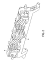
- FIG. 2 shows a front view of a printhead reservoir.
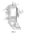
- FIG. 3 shows a cross-sectional view of a comparative example of a printhead reservoir.
- FIG. 4 shows a cross-sectional view of an example of a printhead reservoir according to the invention.
- Figure 1 shows a back view of a printhead reservoir.
- a printhead reservoir contains the ink that the ink jets will eventually spray onto a printing substrate, whether directly, such as onto paper, or indirectly, such as onto a transfer or intermediate surface.
- the printhead reservoir mates with a circuit board or other actuator means that control the operation of the array of jets.
- the circuit board and its coupling to the jets may be referred to as the 'jet stack.'
- the jets draw the ink from a chamber within the reservoir.
- An ink port allows the chamber to be filled with ink.
- the ink port receives pressurized ink through a hose.
- a filter generally prevents particulates from getting into the ink and causing problems with the jetting process. Particulates may clog the jets, causing them to fail or fire off axis.
- the printhead reservoir of Figure 1 has moved the filter out of the jet fluid path, while still keeping the filter in the ink path to regulate particulates in the ink.
- the reservoir 10 has input ink ports such as 12, which couple to a filter 14.
- the filter 14 filters the ink entering the port prior to reaching the chamber 16.
- the back plate of the reservoir may have molded or otherwise formed recesses or cavities to accommodate the filters. With or without the cavities, the back plate may also be referred to as the filter plate.
- the reservoir may comprise a filter plate, a front reservoir and an outlet plate.
- the 'front' reservoir is the reservoir that actually feeds the jets, contrasted with the back reservoir from where the pressurized ink is delivered.
- the chamber 16 is vented to the surrounding atmosphere through a vent hole 18. This alleviates the issues with pressure drop across the filter, as the chamber can regulate its own pressure.
- the vent hole 18 will generally also have an air filter to prevent particulates from contaminating the ink in the chamber 16.
- FIG. 2 shows a front face or outlet plate of the reservoir 10.
- the outlet plate may have several channels such as 20 to direct the ink from the chamber to the jets.
- the circuit board comprising the jet stack would couple to the outlet plate to control the operation of the jets.
- Figure 3 shows a side or cross-sectional view of a comparative example of a reservoir.
- the reservoir 10 has two fluid paths in this example.
- the first fluid path comprises the input fluid path 22 where the ink enters through the ink port 12 and collects in the chamber 16.
- the chamber 16 has vent hole 18, which comprises the air flow path 26.
- the second fluid path is the jet fluid path 24.
- the ink travels along the jet fluid path from the chamber 16 through the channel 20 to the outlet to the jet 28.
- the filter has moved from the jet fluid path, where it causes the problems with excessive pressure drop mentioned above, to the input fluid path. This move allows the jets to pull ink without having the issues with pressure drop.
- the air flow path 26 also contributes to the alleviation of this problem, allowing the chamber to self-regulate the pressure.
- the filter placement in this particular embodiment is outside the vented chamber.
- the placement of the filter 14 with regard to any particular component is optional. However, implementation of the embodiments of the invention should place the filter 'upstream' of a vented chamber between the filtered ink and the jets. In the embodiment of Figure 3 , the filter 14 is outside the vented chamber prior to the input ink port.
- FIG 4 shows an alternative placement of the filter 14, inside the reservoir, but prior to the vented chamber according to an example of the invention.
- the ink enters the reservoir through the ink port 12.
- the filter 14 is actually internal to the reservoir, between the ink port and the vented chamber 16, still residing in the input fluid path.
- the ink may fill the 'intermediate' chamber 30, passing through the filter 14, and spill over into the vented chamber 16.
- the vent hole 18 allows the chamber 16 to self-regulate its pressure. The jets can then draw the ink through the channel 20 without experiencing the pressure drop.
- the filter placement should be in the input fluid path, with a vented chamber lying between the input ink and the jets. This allows the jets to pull ink from a self regulated pressure chamber, and still allows the filter to filter the ink.
- the filter comprises a disc filter made up of a disc of stainless steel felt and a disc of stainless steel mesh both bonded to a formed plate, referred to as the filter plate.
- the filter discs and material mentioned above is an example, but it could be made from alternate materials or shapes. While expensive, the embodiments here use far less of the filter material in four small discs than embodiments using one large piece of filter material for each reservoir. Any materials may be used for the support structure, in this instance the aluminum filter plate. The use of aluminum may have advantages if the rest of the reservoir is constructed out of aluminum as they have the same mechanical properties.
- the reservoir of Figure 1 has four input ports, one each for the colors cyan, magenta, yellow and black. This example implies no limitation and none should be inferred.
- the use of a filter in the fluid path has no limitations as to the number of colors of ink, the types of ink or the size of the reservoir.
Landscapes
- Ink Jet (AREA)
- Particle Formation And Scattering Control In Inkjet Printers (AREA)
Claims (7)
- Vorratsbehälter, der umfasst:einen Tinten-Einleitanschluss (12);eine belüftete Kammer (16), die Tinte von einer Tintenquelle über den Tinten-Einleitanschluss aufnimmt; undeinen Filter (14) auf einem Weg zwischen dem Einleitanschluss und der Kammer,dadurch gekennzeichnet, dass sich der Einleitanschluss in eine Zwischenkammer (30) des Vorratsbehälters hinein öffnet, sich der Filter (14) in der Zwischenkammer (30) befindet und die Zwischenkammer (30) über eine Öffnung in einer Wand zwischen den zwei Kammern mit der belüfteten Kammer (16) verbunden ist.
- Vorratsbehälter nach Anspruch 1, der des Weiteren wenigstens eine Düse (38) zum Ansaugen von Tinte aus der Kammer (16) und auf einem Düsen-Fluidweg (24) zwischen der Kammer und der Düse umfasst.
- Vorratsbehälter nach Anspruch 1 oder Anspruch 2, der des Weiteren einen Einleit-Speicherweg zwischen der Kammer und dem Einleitanschluss umfasst.
- Vorratsbehälter nach einem der vorangehenden Ansprüche, wobei der Filter (14) einen Scheibenfilter umfasst.
- Vorratsbehälter nach Anspruch 4, wobei der Scheibenfilter (14) eine Scheibe aus Gewebe aus rostfreiem Stahl (stainless steel felt disc) und eine Siebscheibe umfasst, die zu einer Filterplatte miteinander verbunden sind.
- Vorratsbehälter nach einem der vorangehenden Ansprüche, wobei der Vorratsbehälter eine Filterplatte, einen vorderen Vorratsbehälter sowie eine Auslassplatte umfasst und die Filterplatte eine Filterplatte mit wenigstens einem Hohlraum zum Aufnehmen des Filters umfasst.
- Vorratsbehälter nach einem der vorangehenden Ansprüche, wobei der Vorratsbehälter eine oder mehrere Lüftungsöffnung/en (18) zwischen dem Vorratsbehälter und einer umgebenden Atmosphäre umfasst.
Applications Claiming Priority (1)
| Application Number | Priority Date | Filing Date | Title |
|---|---|---|---|
| US11/563,294 US7748830B2 (en) | 2006-11-27 | 2006-11-27 | Printhead reservoir with filter external to jet fluid path |
Publications (3)
| Publication Number | Publication Date |
|---|---|
| EP1925453A2 EP1925453A2 (de) | 2008-05-28 |
| EP1925453A3 EP1925453A3 (de) | 2009-01-07 |
| EP1925453B1 true EP1925453B1 (de) | 2013-08-21 |
Family
ID=39154098
Family Applications (1)
| Application Number | Title | Priority Date | Filing Date |
|---|---|---|---|
| EP07121067.8A Ceased EP1925453B1 (de) | 2006-11-27 | 2007-11-20 | Druckkopfbehälter |
Country Status (4)
| Country | Link |
|---|---|
| US (1) | US7748830B2 (de) |
| EP (1) | EP1925453B1 (de) |
| JP (2) | JP2008132782A (de) |
| BR (1) | BRPI0704248A (de) |
Families Citing this family (11)
| Publication number | Priority date | Publication date | Assignee | Title |
|---|---|---|---|---|
| CN1984780B (zh) * | 2004-04-30 | 2010-09-22 | 富士胶片戴麦提克斯公司 | 液滴喷射装置对准 |
| US7837297B2 (en) | 2006-03-03 | 2010-11-23 | Silverbrook Research Pty Ltd | Printhead with non-priming cavities for pulse damping |
| US7654640B2 (en) * | 2007-03-21 | 2010-02-02 | Silverbrook Research Pty Ltd | Printhead with drive circuitry components adjacent the printhead IC |
| US7758177B2 (en) * | 2007-03-21 | 2010-07-20 | Silverbrook Research Pty Ltd | High flowrate filter for inkjet printhead |
| US8079691B2 (en) * | 2009-02-09 | 2011-12-20 | Xerox Corporation | Foam plate for reducing foam in a printhead |
| USD653284S1 (en) * | 2009-07-02 | 2012-01-31 | Fujifilm Dimatix, Inc. | Printhead frame |
| US8517508B2 (en) * | 2009-07-02 | 2013-08-27 | Fujifilm Dimatix, Inc. | Positioning jetting assemblies |
| USD652446S1 (en) * | 2009-07-02 | 2012-01-17 | Fujifilm Dimatix, Inc. | Printhead assembly |
| US8201928B2 (en) | 2009-12-15 | 2012-06-19 | Xerox Corporation | Inkjet ejector having an improved filter |
| US8403457B2 (en) * | 2011-02-04 | 2013-03-26 | Xerox Corporation | Waste ink reclamation apparatus for liquid ink recirculation system |
| US8864293B2 (en) * | 2012-09-12 | 2014-10-21 | Xerox Corporation | Phase change ink reservoir for a phase change inkjet printer |
Family Cites Families (22)
| Publication number | Priority date | Publication date | Assignee | Title |
|---|---|---|---|---|
| JPS5615364A (en) * | 1979-07-18 | 1981-02-14 | Toshiba Corp | Ink jet recorder |
| JP2718724B2 (ja) * | 1987-11-27 | 1998-02-25 | キヤノン株式会社 | インクジェット記録装置、該装置用キャップユニットおよびインクジェットヘッドの回復方法 |
| JPH01228860A (ja) * | 1988-03-09 | 1989-09-12 | Canon Inc | インクジェット記録ヘッド |
| JPH0699589A (ja) * | 1992-09-22 | 1994-04-12 | Brother Ind Ltd | 液体供給装置 |
| JPH0717050A (ja) * | 1993-07-02 | 1995-01-20 | Brother Ind Ltd | インクジェットプリンタにおけるフィルタ装置 |
| DE69518191T2 (de) * | 1994-05-20 | 2001-05-31 | Canon K.K., Tokio/Tokyo | Tintenversorgungsvorrichtung und zugehöriges Tintenstrahlaufzeichnungsgerät |
| US6217164B1 (en) * | 1997-12-09 | 2001-04-17 | Brother Kogyo Kabushiki Kaisha | Ink jet recorder |
| NL1008040C2 (nl) * | 1998-01-16 | 1999-07-19 | Oce Tech Bv | Inktvoorraadhouder geschikt voor aansluiting op een inkjetprintkop alsmede een systeem van een dergelijke inktvoorraadhouder en een inkjetprintkop. |
| US6398354B1 (en) * | 1999-06-30 | 2002-06-04 | Lexmark International, Inc. | Printhead apparatus and printer having separate filtration device and method for attaching said device |
| US6199980B1 (en) * | 1999-11-01 | 2001-03-13 | Xerox Corporation | Efficient fluid filtering device and an ink jet printhead including the same |
| JP3726659B2 (ja) * | 2000-08-30 | 2005-12-14 | ブラザー工業株式会社 | インクジェット記録装置 |
| EP1244558B1 (de) * | 2000-10-23 | 2013-02-27 | Hewlett-Packard Industrial Printing Ltd. | Geschlossenes tintenzuführsystem mit druckkopf-tintendruckregelung und zugehöriges verfahren |
| JP2002144576A (ja) * | 2000-11-17 | 2002-05-21 | Canon Inc | 液体噴射ヘッドおよび液体噴射装置 |
| US7044591B2 (en) | 2002-09-25 | 2006-05-16 | Brother Kogya Kabushiki Kaisha | Ink-jet head, filter assembly used for manufacturing the ink-jet head, and method for manufacturing the ink-jet head using the filter assembly |
| JP2004122500A (ja) * | 2002-09-30 | 2004-04-22 | Canon Inc | 液体収納部と液体使用部とを連通する液体連通構造、および前記液体連通構造を用いた液体供給システムおよびインクジェット記録装置 |
| US7121658B2 (en) * | 2004-01-07 | 2006-10-17 | Xerox Corporation | Print head reservoir having purge vents |
| JP2005279962A (ja) * | 2004-03-26 | 2005-10-13 | Canon Inc | 流体連通構造、該流体連通構造を用いるインクジェット記録ヘッドおよび装置 |
| JP2005335349A (ja) * | 2004-05-31 | 2005-12-08 | Canon Inc | インクジェットヘッドおよびその製造方法 |
| JP2006001200A (ja) * | 2004-06-18 | 2006-01-05 | Seiko Epson Corp | 液体収容室の気体排出構造及び同液体収容室を備えた液体噴射装置 |
| JP4561276B2 (ja) * | 2004-09-22 | 2010-10-13 | 富士ゼロックス株式会社 | インクジェット記録装置 |
| JP2006188047A (ja) * | 2004-12-06 | 2006-07-20 | Konica Minolta Holdings Inc | インクジェットヘッドの製造方法 |
| JP4910368B2 (ja) * | 2005-11-15 | 2012-04-04 | 富士ゼロックス株式会社 | フィルター装置及び液滴吐出装置 |
-
2006
- 2006-11-27 US US11/563,294 patent/US7748830B2/en not_active Expired - Fee Related
-
2007
- 2007-11-20 EP EP07121067.8A patent/EP1925453B1/de not_active Ceased
- 2007-11-21 JP JP2007301470A patent/JP2008132782A/ja active Pending
- 2007-11-27 BR BRPI0704248-5A patent/BRPI0704248A/pt not_active IP Right Cessation
-
2013
- 2013-09-09 JP JP2013185909A patent/JP5726969B2/ja not_active Expired - Fee Related
Also Published As
| Publication number | Publication date |
|---|---|
| JP5726969B2 (ja) | 2015-06-03 |
| US20080122912A1 (en) | 2008-05-29 |
| BRPI0704248A (pt) | 2008-07-15 |
| JP2008132782A (ja) | 2008-06-12 |
| JP2013241024A (ja) | 2013-12-05 |
| US7748830B2 (en) | 2010-07-06 |
| EP1925453A2 (de) | 2008-05-28 |
| EP1925453A3 (de) | 2009-01-07 |
Similar Documents
| Publication | Publication Date | Title |
|---|---|---|
| EP1925453B1 (de) | Druckkopfbehälter | |
| US9630408B2 (en) | Inkjet head that circulates ink | |
| US8684507B2 (en) | Liquid ejecting head, liquid ejecting unit, and liquid ejecting apparatus | |
| EP1368198B1 (de) | Tintenstrahldrucksystem mit filter für pigmentierten strahldrucktinten | |
| US20020180827A1 (en) | Ink jet head | |
| KR20170114926A (ko) | 잉크젯 프린트 헤드에서의 단일 분사 재순환 | |
| JP5178168B2 (ja) | サイホン・ベントを備えたプリントヘッド・リザーバ | |
| JP2008137385A (ja) | チェックバルブ兼用のフィルタを備えるプリントヘッドリザーバ | |
| EP2043869B1 (de) | Druckerpatrone | |
| CN100348420C (zh) | 喷墨头单元和包括此单元的打印机 | |
| JPS61130054A (ja) | インク・ジエツト・プリンタ | |
| US7144100B2 (en) | Purgeable print head reservoir | |
| EP3536508B1 (de) | Druckkopf | |
| EP2360019B1 (de) | Flüssigkeitsausstoßkopf | |
| EP1273447B1 (de) | Akustische Filter für Tintenstrahldruckkopf | |
| US6827422B2 (en) | Liquid suction apparatus for liquid ejecting head and liquid ejecting apparatus | |
| US10668725B2 (en) | Supply manifold in a printhead | |
| US20090179977A1 (en) | Compact ink filter assembly | |
| US10391781B1 (en) | Printhead that evacuates air from a supply manifold | |
| US20090002469A1 (en) | Liquid ejecting head and liquid ejecting apparatus | |
| JP2007182076A (ja) | インクジェット噴射口スタックの外部マニホールド | |
| JP5246599B2 (ja) | 画像形成装置 | |
| KR20150064665A (ko) | 잉크젯 프린트 헤드에서 높은 충전 밀도를 위한 단일 제트 유체 구조 | |
| JP2021011085A (ja) | 液体吐出ヘッド及び液体吐出装置 | |
| JP5950081B2 (ja) | 液体噴射ヘッド及び液体噴射装置 |
Legal Events
| Date | Code | Title | Description |
|---|---|---|---|
| PUAI | Public reference made under article 153(3) epc to a published international application that has entered the european phase |
Free format text: ORIGINAL CODE: 0009012 |
|
| AK | Designated contracting states |
Kind code of ref document: A2 Designated state(s): AT BE BG CH CY CZ DE DK EE ES FI FR GB GR HU IE IS IT LI LT LU LV MC MT NL PL PT RO SE SI SK TR |
|
| AX | Request for extension of the european patent |
Extension state: AL BA HR MK RS |
|
| PUAL | Search report despatched |
Free format text: ORIGINAL CODE: 0009013 |
|
| AK | Designated contracting states |
Kind code of ref document: A3 Designated state(s): AT BE BG CH CY CZ DE DK EE ES FI FR GB GR HU IE IS IT LI LT LU LV MC MT NL PL PT RO SE SI SK TR |
|
| AX | Request for extension of the european patent |
Extension state: AL BA HR MK RS |
|
| 17P | Request for examination filed |
Effective date: 20090707 |
|
| 17Q | First examination report despatched |
Effective date: 20090731 |
|
| AKX | Designation fees paid |
Designated state(s): DE FR GB |
|
| GRAJ | Information related to disapproval of communication of intention to grant by the applicant or resumption of examination proceedings by the epo deleted |
Free format text: ORIGINAL CODE: EPIDOSDIGR1 |
|
| GRAP | Despatch of communication of intention to grant a patent |
Free format text: ORIGINAL CODE: EPIDOSNIGR1 |
|
| INTG | Intention to grant announced |
Effective date: 20130513 |
|
| GRAS | Grant fee paid |
Free format text: ORIGINAL CODE: EPIDOSNIGR3 |
|
| GRAA | (expected) grant |
Free format text: ORIGINAL CODE: 0009210 |
|
| AK | Designated contracting states |
Kind code of ref document: B1 Designated state(s): DE FR GB |
|
| REG | Reference to a national code |
Ref country code: GB Ref legal event code: FG4D |
|
| REG | Reference to a national code |
Ref country code: DE Ref legal event code: R096 Ref document number: 602007032345 Country of ref document: DE Effective date: 20131017 |
|
| PLBE | No opposition filed within time limit |
Free format text: ORIGINAL CODE: 0009261 |
|
| STAA | Information on the status of an ep patent application or granted ep patent |
Free format text: STATUS: NO OPPOSITION FILED WITHIN TIME LIMIT |
|
| 26N | No opposition filed |
Effective date: 20140522 |
|
| REG | Reference to a national code |
Ref country code: DE Ref legal event code: R097 Ref document number: 602007032345 Country of ref document: DE Effective date: 20140522 |
|
| REG | Reference to a national code |
Ref country code: FR Ref legal event code: PLFP Year of fee payment: 9 |
|
| REG | Reference to a national code |
Ref country code: FR Ref legal event code: PLFP Year of fee payment: 10 |
|
| REG | Reference to a national code |
Ref country code: FR Ref legal event code: PLFP Year of fee payment: 11 |
|
| PGFP | Annual fee paid to national office [announced via postgrant information from national office to epo] |
Ref country code: DE Payment date: 20171019 Year of fee payment: 11 Ref country code: FR Payment date: 20171020 Year of fee payment: 11 |
|
| PGFP | Annual fee paid to national office [announced via postgrant information from national office to epo] |
Ref country code: GB Payment date: 20171020 Year of fee payment: 11 |
|
| REG | Reference to a national code |
Ref country code: DE Ref legal event code: R119 Ref document number: 602007032345 Country of ref document: DE |
|
| GBPC | Gb: european patent ceased through non-payment of renewal fee |
Effective date: 20181120 |
|
| PG25 | Lapsed in a contracting state [announced via postgrant information from national office to epo] |
Ref country code: FR Free format text: LAPSE BECAUSE OF NON-PAYMENT OF DUE FEES Effective date: 20181130 Ref country code: DE Free format text: LAPSE BECAUSE OF NON-PAYMENT OF DUE FEES Effective date: 20190601 |
|
| PG25 | Lapsed in a contracting state [announced via postgrant information from national office to epo] |
Ref country code: GB Free format text: LAPSE BECAUSE OF NON-PAYMENT OF DUE FEES Effective date: 20181120 |