EP1925376A1 - Profilierkopf mit Vorrichtung zum Biegungsausgleich sowie Profiliermaschine mit einem solchen Profilierkopf - Google Patents
Profilierkopf mit Vorrichtung zum Biegungsausgleich sowie Profiliermaschine mit einem solchen Profilierkopf Download PDFInfo
- Publication number
- EP1925376A1 EP1925376A1 EP06291815A EP06291815A EP1925376A1 EP 1925376 A1 EP1925376 A1 EP 1925376A1 EP 06291815 A EP06291815 A EP 06291815A EP 06291815 A EP06291815 A EP 06291815A EP 1925376 A1 EP1925376 A1 EP 1925376A1
- Authority
- EP
- European Patent Office
- Prior art keywords
- profiling
- head according
- shafts
- ring
- bearing
- Prior art date
- Legal status (The legal status is an assumption and is not a legal conclusion. Google has not performed a legal analysis and makes no representation as to the accuracy of the status listed.)
- Granted
Links
Images


Classifications
-
- B—PERFORMING OPERATIONS; TRANSPORTING
- B21—MECHANICAL METAL-WORKING WITHOUT ESSENTIALLY REMOVING MATERIAL; PUNCHING METAL
- B21D—WORKING OR PROCESSING OF SHEET METAL OR METAL TUBES, RODS OR PROFILES WITHOUT ESSENTIALLY REMOVING MATERIAL; PUNCHING METAL
- B21D5/00—Bending sheet metal along straight lines, e.g. to form simple curves
- B21D5/06—Bending sheet metal along straight lines, e.g. to form simple curves by drawing procedure making use of dies or forming-rollers, e.g. making profiles
- B21D5/08—Bending sheet metal along straight lines, e.g. to form simple curves by drawing procedure making use of dies or forming-rollers, e.g. making profiles making use of forming-rollers
-
- B—PERFORMING OPERATIONS; TRANSPORTING
- B21—MECHANICAL METAL-WORKING WITHOUT ESSENTIALLY REMOVING MATERIAL; PUNCHING METAL
- B21D—WORKING OR PROCESSING OF SHEET METAL OR METAL TUBES, RODS OR PROFILES WITHOUT ESSENTIALLY REMOVING MATERIAL; PUNCHING METAL
- B21D5/00—Bending sheet metal along straight lines, e.g. to form simple curves
- B21D5/14—Bending sheet metal along straight lines, e.g. to form simple curves by passing between rollers
Definitions
- the invention relates to a profiling head equipped with anti-bending means for forming, by rolling, plates of sheet metal or equivalent having a certain profile, for example U, V or other.
- the invention also relates to machines equipped with such profiling heads.
- a profiling line of a profiling machine the sheet is progressively formed by passing through profiling heads equipped with rolling cassettes.
- the profiling machines comprise one or more profiling lines until the desired profile is reached.
- the sheet is unrolled from a reel, formed by passing through the rolls of rolling profiling heads, then collected on an output conveyor equipped with plate cutting shears and finally stacked.
- bending machines can be provided for bending the shaped sheet metal plates. Electronic equipment for controlling the profiling lines is also provided.
- Each rolling cassette of the profiling heads comprises a set of two parallel shafts on which rollers and spacers are mounted.
- the sheet is formed by passing between these rolling means respectively having a complementary profile, the two shafts being adjusted in distance on vertical uprights according to the sheet thicknesses.
- a support frame for the shafts comprising the vertical uprights and a base is provided.
- the current trend is to substantially reduce the diameter of the mounting shafts and rollers.
- the use of such shafts cause problems of bending and adjustment of the trees due to their deformation due to the dynamic stresses generated by the weight of the sheets and their advancement in the profiling lines. Adjustment can then be achieved by clamping the rollers of the rollers, which causes in time a digging effect of the rings by the work of the shaft.
- the trees are never perfectly cylindrical and their runout may, in rotation, cause their ejection.
- the invention provides to make the adjustment of all shafts and forming means integral and to provide bending adaptation means.
- the subject of the invention is a profiling head comprising at least one roller forming cassette comprising a set of two parallel shafts on which rollers separated by spacers are mounted to form a rolling tool, and a frame comprising vertical uprights for supporting the shafts and a base for fixing these uprights, which uprights are provided with means for vertical adjustment of the shafts.
- the profiling head also comprises tool alignment adjustment elements, mounted laterally on each shaft in connection with at least one vertical upright, and anti-bending adjustment elements mounted substantially in the central position of each connected shaft. with the base and / or a control beam in the case where such a control beam is mounted on the vertical uprights of the frame parallel to the shafts.
- the invention also relates to a profiling machine comprising a sheet metal storage coil, several progressive profiling heads as defined above, an output conveyor equipped with plate cutting shears profiled sheet, a tray of stacking of the plates and electronic equipment for driving profiling lines formed by each profiled sheet.
- bending machines can be provided for bending the shaped sheet metal plates.
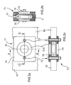
- the profiling head 1 view in main section is equipped with a rolling cassette 2 having a set of two parallel shafts 20 and 30.
- Rollers 201 to 217 are mounted on the shaft 20 and the rollers 301 to 310 are mounted on the shaft 30. Most of these rollers are mounted on bearings 3. Spacers 200 and 300 are mounted directly on the shafts 20 and 30 to wedge the rollers of one shaft on the corresponding rollers of the other shaft. The rollers and spacers form the rolling tool.
- the forming sheet is inserted between the rollers thus positioned opposite and respectively having a complementary profile.
- the two shafts being adjusted in distance on lateral uprights 41 and 51 depending on the desired gap between the rollers of the trees located opposite for a given thickness of sheet to be formed.
- a tree support frame comprises the vertical uprights 41, 51 and a base 60 on which these uprights are fixed with parts 42, 43 and 52, 53 forming vices.
- the shafts 20 and 30 are mounted parallel to the uprights 41 and 51 by means of lateral adjustment elements, respectively 61 and 71, mounted on the shafts with the aid of bearings 3 and fixed to these uprights.
- the amounts 41 and 51 are provided with stops 44 and 54 for vertical adjustment of the shafts, whose position is locked by nuts 45, 46 and 55, 56.
- the mounting shafts and rollers have a reduced diameter compared to those conventionally used.
- the diameter of the shafts is 60 mm, whereas a conventional diameter is 100 mm.
- the lateral adjusting elements 71 fixed to the upright 51 comprise tooling alignment means by centering, as detailed below, while the adjustment elements 61 mounted on the other upright 41 do not include a centering system. .
- an adjusting beam 80 is mounted on the vertical uprights, using connectors 81 and adjusting nuts 82, parallel to the mounting shafts 20 and 30.
- Anti-bending adjustment elements 90 and 91 are mounted substantially in the central position of each shaft, respectively in connection with the base 60 and the adjusting beam 80 via the rods 4 and 5.
- the rod 4 has an adjustable height through a set 6 nut / lock nut mounted on a threaded end 4a of this rod 4. The rod is inserted into the non-threaded orifice 7a of a nozzle 7.
- the other rod 5 is fixedly mounted on the adjustment beam 80 to the using means known to those skilled in the art.
- the lateral adjustment elements 61, 71 and anti-flexion 90, 91 are mounted on bearings 3 and 3a, and automatically adjust to the vertical adjustment made on the stops 44 and 54.
- FIGS. 2a, 2b and 2c illustrate a side view and sectional views of FIG. 1 concentrated on an alignment alignment element 71 of the tooling.
- an alignment alignment element 71 of the tooling comprises two centering bolts with threaded screws 72 and 73.
- the bolts are mounted on two flanges 74 and 75, disposed externally on two walls 57 and 58 of the upright 51, to pass through the walls 57 and 58.
- FIG. 3a an anti-bending adjustment element is illustrated in FIG. 3a.
- Such an element 90 comprises a conical ring 92a slotted longitudinally along the axis X'X of the shaft 20.
- the ring has a thickness sufficient to serve as a spacer.
- On this ring 92a is mounted a bearing 3a whose inner bearing 30 has the same taper as that of the ring 92a.
- the relative position of the bearing 3a on the ring is set laterally by relative movement (arrow F) of this bearing along the conical ring 92a by means of a nut 32 in connection with a threaded portion 93 of the split ring.
- Such a displacement simultaneously induces a constriction or loosening of this ring.
- FIG. 3b Another anti-flexion element 91 is illustrated in FIG. 3b.
- This element consists of a split ring 92b of the same type as the ring 92a and a bearing 3a conical inner bearing 30, identical to the bearing associated with the ring 92a.
- a lateral displacement causes the rolling of the bearing 3a on the ring 92b whose diameter remains constant by increasing or decreasing the opening of the slot of the ring. The displacement is provided by the roller 305 which bears against the bearing 3a.
- FIG. 4 illustrates, in cross-section along a variable plane AA of FIG. 1, the two anti-bending adjustment elements 90 and 91 of FIGS. 3a and 3b.
- the figure highlights the use of external bearings partial 94a, 94b formed of a cylinder section disposed opposite the connecting rod 4 to the base 60 or the rod 5 connecting to the beam 80.
- the ends of the rods 4 and 5 are respectively fixed in the bearings Partials 94a and 94b.
- This reduction in bearing length advantageous in terms of cost, is justified by the fact that only an outer bearing portion is useful for adjustment.
- the inner bearings 30 remain complete.
Landscapes
- Engineering & Computer Science (AREA)
- Mechanical Engineering (AREA)
- Bending Of Plates, Rods, And Pipes (AREA)
- Machine Tool Units (AREA)
- Straightening Metal Sheet-Like Bodies (AREA)
Priority Applications (9)
| Application Number | Priority Date | Filing Date | Title |
|---|---|---|---|
| EP06291815A EP1925376B1 (de) | 2006-11-24 | 2006-11-24 | Profilierkopf mit Vorrichtung zum Biegungsausgleich sowie Profiliermaschine mit einem solchen Profilierkopf |
| AT06291815T ATE550115T1 (de) | 2006-11-24 | 2006-11-24 | Profilierkopf mit vorrichtung zum biegungsausgleich sowie profiliermaschine mit einem solchen profilierkopf |
| JP2009537668A JP2010510072A (ja) | 2006-11-24 | 2007-11-07 | 耐曲げ異形加工(profiling)ヘッド及び当該ヘッドが備え付けられる異形加工機 |
| BRPI0719145-6A BRPI0719145A2 (pt) | 2006-11-24 | 2007-11-07 | Cabeça de perfilagem e máquina de perfilar equipada com tais cabeças. |
| US12/516,129 US20100018274A1 (en) | 2006-11-24 | 2007-11-07 | Anti-bending profiling head and profiling machine fitted with such heads |
| PCT/FR2007/001834 WO2008068404A2 (fr) | 2006-11-24 | 2007-11-07 | Tete de profilage antiflexion et machine a profiler equipee de telles tetes |
| NZ577162A NZ577162A (en) | 2006-11-24 | 2007-11-07 | An anti-bending profiling head and a profiling machine fitted with such heads |
| CA002670441A CA2670441A1 (fr) | 2006-11-24 | 2007-11-07 | Tete de profilage antiflexion et machine a profiler equipee de telles tetes |
| AU2007330632A AU2007330632A1 (en) | 2006-11-24 | 2007-11-07 | Antiflexion profiling head and profiling machine equipped with the same<0} |
Applications Claiming Priority (1)
| Application Number | Priority Date | Filing Date | Title |
|---|---|---|---|
| EP06291815A EP1925376B1 (de) | 2006-11-24 | 2006-11-24 | Profilierkopf mit Vorrichtung zum Biegungsausgleich sowie Profiliermaschine mit einem solchen Profilierkopf |
Related Child Applications (1)
| Application Number | Title | Priority Date | Filing Date |
|---|---|---|---|
| EP10015249.5 Division-Into | 2010-12-03 |
Publications (2)
| Publication Number | Publication Date |
|---|---|
| EP1925376A1 true EP1925376A1 (de) | 2008-05-28 |
| EP1925376B1 EP1925376B1 (de) | 2012-03-21 |
Family
ID=38006578
Family Applications (1)
| Application Number | Title | Priority Date | Filing Date |
|---|---|---|---|
| EP06291815A Not-in-force EP1925376B1 (de) | 2006-11-24 | 2006-11-24 | Profilierkopf mit Vorrichtung zum Biegungsausgleich sowie Profiliermaschine mit einem solchen Profilierkopf |
Country Status (9)
| Country | Link |
|---|---|
| US (1) | US20100018274A1 (de) |
| EP (1) | EP1925376B1 (de) |
| JP (1) | JP2010510072A (de) |
| AT (1) | ATE550115T1 (de) |
| AU (1) | AU2007330632A1 (de) |
| BR (1) | BRPI0719145A2 (de) |
| CA (1) | CA2670441A1 (de) |
| NZ (1) | NZ577162A (de) |
| WO (1) | WO2008068404A2 (de) |
Cited By (3)
| Publication number | Priority date | Publication date | Assignee | Title |
|---|---|---|---|---|
| CN101817020B (zh) * | 2009-02-27 | 2012-03-14 | 北新集团建材股份有限公司 | 一种轻钢龙骨加工中轧辊模具快速变换机构 |
| CN104772334A (zh) * | 2015-04-09 | 2015-07-15 | 肇庆北新建材有限公司 | 卡式龙骨新的成型方式 |
| CN114074114A (zh) * | 2020-08-12 | 2022-02-22 | 浙江惠创智能装备有限公司 | 一种光伏圆丝铜带的生产设备 |
Families Citing this family (3)
| Publication number | Priority date | Publication date | Assignee | Title |
|---|---|---|---|---|
| DE10243677A1 (de) * | 2002-09-20 | 2004-04-01 | Sms Demag Ag | Reibungsarmes Biegesystem in einem Mehrwalzen-Walzgerüst |
| CN107150077B (zh) * | 2016-03-04 | 2019-09-27 | 北新集团建材股份有限公司 | 调节用轧辊设备和龙骨开口尺寸的控制方法 |
| CN113441547B (zh) * | 2021-07-02 | 2022-08-16 | 太原理工大学 | 一种头部预弯曲改善镁/铝复合板波平连续轧制的方法 |
Citations (4)
| Publication number | Priority date | Publication date | Assignee | Title |
|---|---|---|---|---|
| FR2484874A1 (fr) * | 1980-06-18 | 1981-12-24 | Krueckels Gerhard | Machine permettant d'obtenir en continu des profiles a section variable en fonction de la longueur et procede de fabrication correspondant |
| EP0621087A1 (de) * | 1993-04-22 | 1994-10-26 | Hitachi, Ltd. | Walzwerk und Verfahren |
| DE9416413U1 (de) * | 1994-10-12 | 1994-12-01 | Helwig, Roger, 59872 Meschede | Walzengestell einer Kalt-Profilieranlage |
| EP1245302A1 (de) * | 2001-03-27 | 2002-10-02 | Dreistern-Werk Maschinenbau GmbH & co. KG | Profiliermaschine mit mehreren, in Linie hintereinander angeordneten Umformstationen |
Family Cites Families (5)
| Publication number | Priority date | Publication date | Assignee | Title |
|---|---|---|---|---|
| JPS5358466A (en) * | 1976-11-06 | 1978-05-26 | Ooemu Kougiyou Kk | Method for fabricating metal shaped material |
| JPH0238125U (de) * | 1988-08-27 | 1990-03-14 | ||
| JP2521645Y2 (ja) * | 1993-11-22 | 1996-12-25 | 冷間ロール成形システム株式会社 | ロール成形機 |
| JPH0989698A (ja) * | 1995-09-22 | 1997-04-04 | Toyota Motor Corp | 棒状部材の強制力測定方法およびその装置 |
| JPH10166055A (ja) * | 1996-12-10 | 1998-06-23 | Tokyo Steel Center Kk | 長尺鋼材のキャンバー矯正方法およびそのための装置を備えたミニレベラー設備 |
-
2006
- 2006-11-24 AT AT06291815T patent/ATE550115T1/de active
- 2006-11-24 EP EP06291815A patent/EP1925376B1/de not_active Not-in-force
-
2007
- 2007-11-07 JP JP2009537668A patent/JP2010510072A/ja active Pending
- 2007-11-07 BR BRPI0719145-6A patent/BRPI0719145A2/pt not_active IP Right Cessation
- 2007-11-07 CA CA002670441A patent/CA2670441A1/fr not_active Abandoned
- 2007-11-07 WO PCT/FR2007/001834 patent/WO2008068404A2/fr not_active Ceased
- 2007-11-07 US US12/516,129 patent/US20100018274A1/en not_active Abandoned
- 2007-11-07 NZ NZ577162A patent/NZ577162A/en unknown
- 2007-11-07 AU AU2007330632A patent/AU2007330632A1/en not_active Abandoned
Patent Citations (4)
| Publication number | Priority date | Publication date | Assignee | Title |
|---|---|---|---|---|
| FR2484874A1 (fr) * | 1980-06-18 | 1981-12-24 | Krueckels Gerhard | Machine permettant d'obtenir en continu des profiles a section variable en fonction de la longueur et procede de fabrication correspondant |
| EP0621087A1 (de) * | 1993-04-22 | 1994-10-26 | Hitachi, Ltd. | Walzwerk und Verfahren |
| DE9416413U1 (de) * | 1994-10-12 | 1994-12-01 | Helwig, Roger, 59872 Meschede | Walzengestell einer Kalt-Profilieranlage |
| EP1245302A1 (de) * | 2001-03-27 | 2002-10-02 | Dreistern-Werk Maschinenbau GmbH & co. KG | Profiliermaschine mit mehreren, in Linie hintereinander angeordneten Umformstationen |
Cited By (3)
| Publication number | Priority date | Publication date | Assignee | Title |
|---|---|---|---|---|
| CN101817020B (zh) * | 2009-02-27 | 2012-03-14 | 北新集团建材股份有限公司 | 一种轻钢龙骨加工中轧辊模具快速变换机构 |
| CN104772334A (zh) * | 2015-04-09 | 2015-07-15 | 肇庆北新建材有限公司 | 卡式龙骨新的成型方式 |
| CN114074114A (zh) * | 2020-08-12 | 2022-02-22 | 浙江惠创智能装备有限公司 | 一种光伏圆丝铜带的生产设备 |
Also Published As
| Publication number | Publication date |
|---|---|
| EP1925376B1 (de) | 2012-03-21 |
| BRPI0719145A2 (pt) | 2014-02-11 |
| CA2670441A1 (fr) | 2008-06-12 |
| ATE550115T1 (de) | 2012-04-15 |
| JP2010510072A (ja) | 2010-04-02 |
| NZ577162A (en) | 2011-08-26 |
| WO2008068404A3 (fr) | 2008-07-24 |
| WO2008068404A2 (fr) | 2008-06-12 |
| AU2007330632A1 (en) | 2008-06-12 |
| US20100018274A1 (en) | 2010-01-28 |
Similar Documents
| Publication | Publication Date | Title |
|---|---|---|
| WO2008068404A2 (fr) | Tete de profilage antiflexion et machine a profiler equipee de telles tetes | |
| EP3181312B1 (de) | Regulierbare anordnung zur umwandlung einer ebenen halterung, kassette, einheit und damit ausgerüstete maschine | |
| EP1331054B1 (de) | Vorrichtung zum rotierenden Formgeben von einem Band oder einem Blech | |
| FR2493763A1 (fr) | Chassis de tension d'un ecran pour l'impression en serigraphie | |
| FR2573344A1 (fr) | Machine de traitement d'une matiere en bande | |
| GB2253025A (en) | Roller conveyors. | |
| WO2013053900A1 (fr) | Systeme de guidage d'un arbre vertical de machine tournante et installation de conversion d'energie incorporant un tel systeme | |
| CH700557A2 (fr) | Presse plieuse pour le pliage de feuilles. | |
| EP0907432B1 (de) | Metallplattenbiegevorrichtung mit offsetdruckrollen | |
| CA2249626A1 (fr) | Cylindre pour une installation de laminage ou de coulee continue des metaux | |
| FR2771327A1 (fr) | Procede et equipement de decoupage d'un materiau en forme de feuille | |
| EP0368686B1 (de) | Automatisierbare Rundwalzeneinrichtung mit verzahnten Walzen | |
| FR2663315A1 (fr) | Montage reglable d'une roue de roulement. | |
| US20060189426A1 (en) | Eccentric bracket assembly | |
| EP3999789B1 (de) | Zuganker, insbesondere für eine gitterstruktur | |
| CA1176679A (fr) | Stator a circuit magnetique feuillete avec doigts de serrage pour machine dynamoelectrique tournante, notamment du type a bulbe immerge | |
| EP3390254B1 (de) | Umlenkrolle zum abwickeln einer spule eines bandförmigen produkts | |
| EP4169648B1 (de) | Absetzkopf einer 3d-druckmaschine, der zum gleichzeitigen absetzen mehrerer fäden konfiguriert ist, und 3d-druckmaschine mit diesem absetzkopf | |
| BE1004786A3 (fr) | Appareil pour fabriquer un tube ondule. | |
| EP1463401A2 (de) | Bodenbearbeitungswalze mit schraubenförmigen elementen | |
| EP1498650A1 (de) | Führungsvorrichtung für hydraulische Schläuche | |
| FR2859655A1 (fr) | Systeme de protection, en particulier pour convoyeurs | |
| FR2715978A1 (fr) | Dispositif d'accouplemeent de portions d'axe ou d'arbre et dispositif de montage comprenant de tels dispositifs d'accouplement. | |
| FR2806026A1 (fr) | Cassette de decoupage rotatif de type recuperable pour machines de transformation des papiers et cartons | |
| EP0329584A1 (de) | Rahmen-Spannvorrichtung |
Legal Events
| Date | Code | Title | Description |
|---|---|---|---|
| PUAI | Public reference made under article 153(3) epc to a published international application that has entered the european phase |
Free format text: ORIGINAL CODE: 0009012 |
|
| AK | Designated contracting states |
Kind code of ref document: A1 Designated state(s): AT BE BG CH CY CZ DE DK EE ES FI FR GB GR HU IE IS IT LI LT LU LV MC NL PL PT RO SE SI SK TR |
|
| AX | Request for extension of the european patent |
Extension state: AL BA HR MK RS |
|
| 17P | Request for examination filed |
Effective date: 20081023 |
|
| 17Q | First examination report despatched |
Effective date: 20081124 |
|
| AKX | Designation fees paid |
Designated state(s): AT BE BG CH CY CZ DE DK EE ES FI FR GB GR HU IE IS IT LI LT LU LV MC NL PL PT RO SE SI SK TR |
|
| GRAP | Despatch of communication of intention to grant a patent |
Free format text: ORIGINAL CODE: EPIDOSNIGR1 |
|
| GRAC | Information related to communication of intention to grant a patent modified |
Free format text: ORIGINAL CODE: EPIDOSCIGR1 |
|
| GRAJ | Information related to disapproval of communication of intention to grant by the applicant or resumption of examination proceedings by the epo deleted |
Free format text: ORIGINAL CODE: EPIDOSDIGR1 |
|
| GRAP | Despatch of communication of intention to grant a patent |
Free format text: ORIGINAL CODE: EPIDOSNIGR1 |
|
| GRAS | Grant fee paid |
Free format text: ORIGINAL CODE: EPIDOSNIGR3 |
|
| GRAA | (expected) grant |
Free format text: ORIGINAL CODE: 0009210 |
|
| AK | Designated contracting states |
Kind code of ref document: B1 Designated state(s): AT BE BG CH CY CZ DE DK EE ES FI FR GB GR HU IE IS IT LI LT LU LV MC NL PL PT RO SE SI SK TR |
|
| REG | Reference to a national code |
Ref country code: GB Ref legal event code: FG4D Free format text: NOT ENGLISH |
|
| REG | Reference to a national code |
Ref country code: CH Ref legal event code: EP |
|
| REG | Reference to a national code |
Ref country code: IE Ref legal event code: FG4D Free format text: LANGUAGE OF EP DOCUMENT: FRENCH |
|
| REG | Reference to a national code |
Ref country code: AT Ref legal event code: REF Ref document number: 550115 Country of ref document: AT Kind code of ref document: T Effective date: 20120415 |
|
| REG | Reference to a national code |
Ref country code: DE Ref legal event code: R096 Ref document number: 602006028296 Country of ref document: DE Effective date: 20120516 |
|
| REG | Reference to a national code |
Ref country code: NL Ref legal event code: VDEP Effective date: 20120321 |
|
| PG25 | Lapsed in a contracting state [announced via postgrant information from national office to epo] |
Ref country code: LT Free format text: LAPSE BECAUSE OF FAILURE TO SUBMIT A TRANSLATION OF THE DESCRIPTION OR TO PAY THE FEE WITHIN THE PRESCRIBED TIME-LIMIT Effective date: 20120321 |
|
| LTIE | Lt: invalidation of european patent or patent extension |
Effective date: 20120321 |
|
| PG25 | Lapsed in a contracting state [announced via postgrant information from national office to epo] |
Ref country code: FI Free format text: LAPSE BECAUSE OF FAILURE TO SUBMIT A TRANSLATION OF THE DESCRIPTION OR TO PAY THE FEE WITHIN THE PRESCRIBED TIME-LIMIT Effective date: 20120321 Ref country code: GR Free format text: LAPSE BECAUSE OF FAILURE TO SUBMIT A TRANSLATION OF THE DESCRIPTION OR TO PAY THE FEE WITHIN THE PRESCRIBED TIME-LIMIT Effective date: 20120622 Ref country code: LV Free format text: LAPSE BECAUSE OF FAILURE TO SUBMIT A TRANSLATION OF THE DESCRIPTION OR TO PAY THE FEE WITHIN THE PRESCRIBED TIME-LIMIT Effective date: 20120321 |
|
| REG | Reference to a national code |
Ref country code: AT Ref legal event code: MK05 Ref document number: 550115 Country of ref document: AT Kind code of ref document: T Effective date: 20120321 |
|
| PG25 | Lapsed in a contracting state [announced via postgrant information from national office to epo] |
Ref country code: CY Free format text: LAPSE BECAUSE OF FAILURE TO SUBMIT A TRANSLATION OF THE DESCRIPTION OR TO PAY THE FEE WITHIN THE PRESCRIBED TIME-LIMIT Effective date: 20120321 |
|
| PG25 | Lapsed in a contracting state [announced via postgrant information from national office to epo] |
Ref country code: PL Free format text: LAPSE BECAUSE OF FAILURE TO SUBMIT A TRANSLATION OF THE DESCRIPTION OR TO PAY THE FEE WITHIN THE PRESCRIBED TIME-LIMIT Effective date: 20120321 Ref country code: CZ Free format text: LAPSE BECAUSE OF FAILURE TO SUBMIT A TRANSLATION OF THE DESCRIPTION OR TO PAY THE FEE WITHIN THE PRESCRIBED TIME-LIMIT Effective date: 20120321 Ref country code: SE Free format text: LAPSE BECAUSE OF FAILURE TO SUBMIT A TRANSLATION OF THE DESCRIPTION OR TO PAY THE FEE WITHIN THE PRESCRIBED TIME-LIMIT Effective date: 20120321 Ref country code: EE Free format text: LAPSE BECAUSE OF FAILURE TO SUBMIT A TRANSLATION OF THE DESCRIPTION OR TO PAY THE FEE WITHIN THE PRESCRIBED TIME-LIMIT Effective date: 20120321 Ref country code: SI Free format text: LAPSE BECAUSE OF FAILURE TO SUBMIT A TRANSLATION OF THE DESCRIPTION OR TO PAY THE FEE WITHIN THE PRESCRIBED TIME-LIMIT Effective date: 20120321 Ref country code: RO Free format text: LAPSE BECAUSE OF FAILURE TO SUBMIT A TRANSLATION OF THE DESCRIPTION OR TO PAY THE FEE WITHIN THE PRESCRIBED TIME-LIMIT Effective date: 20120321 Ref country code: IS Free format text: LAPSE BECAUSE OF FAILURE TO SUBMIT A TRANSLATION OF THE DESCRIPTION OR TO PAY THE FEE WITHIN THE PRESCRIBED TIME-LIMIT Effective date: 20120721 |
|
| PG25 | Lapsed in a contracting state [announced via postgrant information from national office to epo] |
Ref country code: PT Free format text: LAPSE BECAUSE OF FAILURE TO SUBMIT A TRANSLATION OF THE DESCRIPTION OR TO PAY THE FEE WITHIN THE PRESCRIBED TIME-LIMIT Effective date: 20120723 Ref country code: SK Free format text: LAPSE BECAUSE OF FAILURE TO SUBMIT A TRANSLATION OF THE DESCRIPTION OR TO PAY THE FEE WITHIN THE PRESCRIBED TIME-LIMIT Effective date: 20120321 |
|
| PLBE | No opposition filed within time limit |
Free format text: ORIGINAL CODE: 0009261 |
|
| STAA | Information on the status of an ep patent application or granted ep patent |
Free format text: STATUS: NO OPPOSITION FILED WITHIN TIME LIMIT |
|
| PG25 | Lapsed in a contracting state [announced via postgrant information from national office to epo] |
Ref country code: AT Free format text: LAPSE BECAUSE OF FAILURE TO SUBMIT A TRANSLATION OF THE DESCRIPTION OR TO PAY THE FEE WITHIN THE PRESCRIBED TIME-LIMIT Effective date: 20120321 Ref country code: NL Free format text: LAPSE BECAUSE OF FAILURE TO SUBMIT A TRANSLATION OF THE DESCRIPTION OR TO PAY THE FEE WITHIN THE PRESCRIBED TIME-LIMIT Effective date: 20120321 Ref country code: DK Free format text: LAPSE BECAUSE OF FAILURE TO SUBMIT A TRANSLATION OF THE DESCRIPTION OR TO PAY THE FEE WITHIN THE PRESCRIBED TIME-LIMIT Effective date: 20120321 |
|
| 26N | No opposition filed |
Effective date: 20130102 |
|
| REG | Reference to a national code |
Ref country code: DE Ref legal event code: R097 Ref document number: 602006028296 Country of ref document: DE Effective date: 20130102 |
|
| PG25 | Lapsed in a contracting state [announced via postgrant information from national office to epo] |
Ref country code: ES Free format text: LAPSE BECAUSE OF FAILURE TO SUBMIT A TRANSLATION OF THE DESCRIPTION OR TO PAY THE FEE WITHIN THE PRESCRIBED TIME-LIMIT Effective date: 20120702 |
|
| PGFP | Annual fee paid to national office [announced via postgrant information from national office to epo] |
Ref country code: FR Payment date: 20130319 Year of fee payment: 7 Ref country code: DE Payment date: 20130221 Year of fee payment: 7 |
|
| PGFP | Annual fee paid to national office [announced via postgrant information from national office to epo] |
Ref country code: BE Payment date: 20130220 Year of fee payment: 7 |
|
| REG | Reference to a national code |
Ref country code: CH Ref legal event code: PL |
|
| GBPC | Gb: european patent ceased through non-payment of renewal fee |
Effective date: 20121124 |
|
| PG25 | Lapsed in a contracting state [announced via postgrant information from national office to epo] |
Ref country code: CH Free format text: LAPSE BECAUSE OF NON-PAYMENT OF DUE FEES Effective date: 20121130 Ref country code: LI Free format text: LAPSE BECAUSE OF NON-PAYMENT OF DUE FEES Effective date: 20121130 Ref country code: BG Free format text: LAPSE BECAUSE OF FAILURE TO SUBMIT A TRANSLATION OF THE DESCRIPTION OR TO PAY THE FEE WITHIN THE PRESCRIBED TIME-LIMIT Effective date: 20120621 |
|
| REG | Reference to a national code |
Ref country code: IE Ref legal event code: MM4A |
|
| PG25 | Lapsed in a contracting state [announced via postgrant information from national office to epo] |
Ref country code: IE Free format text: LAPSE BECAUSE OF NON-PAYMENT OF DUE FEES Effective date: 20121124 |
|
| PG25 | Lapsed in a contracting state [announced via postgrant information from national office to epo] |
Ref country code: GB Free format text: LAPSE BECAUSE OF NON-PAYMENT OF DUE FEES Effective date: 20121124 |
|
| PG25 | Lapsed in a contracting state [announced via postgrant information from national office to epo] |
Ref country code: MC Free format text: LAPSE BECAUSE OF NON-PAYMENT OF DUE FEES Effective date: 20121130 Ref country code: TR Free format text: LAPSE BECAUSE OF FAILURE TO SUBMIT A TRANSLATION OF THE DESCRIPTION OR TO PAY THE FEE WITHIN THE PRESCRIBED TIME-LIMIT Effective date: 20120321 |
|
| PG25 | Lapsed in a contracting state [announced via postgrant information from national office to epo] |
Ref country code: LU Free format text: LAPSE BECAUSE OF NON-PAYMENT OF DUE FEES Effective date: 20121124 |
|
| BERE | Be: lapsed |
Owner name: MINISCLOUX, FRANCIS Effective date: 20131130 |
|
| PG25 | Lapsed in a contracting state [announced via postgrant information from national office to epo] |
Ref country code: HU Free format text: LAPSE BECAUSE OF FAILURE TO SUBMIT A TRANSLATION OF THE DESCRIPTION OR TO PAY THE FEE WITHIN THE PRESCRIBED TIME-LIMIT Effective date: 20061124 |
|
| REG | Reference to a national code |
Ref country code: FR Ref legal event code: ST Effective date: 20140731 |
|
| REG | Reference to a national code |
Ref country code: DE Ref legal event code: R119 Ref document number: 602006028296 Country of ref document: DE Effective date: 20140603 |
|
| PG25 | Lapsed in a contracting state [announced via postgrant information from national office to epo] |
Ref country code: IT Free format text: LAPSE BECAUSE OF NON-PAYMENT OF DUE FEES Effective date: 20131124 Ref country code: DE Free format text: LAPSE BECAUSE OF NON-PAYMENT OF DUE FEES Effective date: 20140603 |
|
| PG25 | Lapsed in a contracting state [announced via postgrant information from national office to epo] |
Ref country code: BE Free format text: LAPSE BECAUSE OF NON-PAYMENT OF DUE FEES Effective date: 20131130 |
|
| PG25 | Lapsed in a contracting state [announced via postgrant information from national office to epo] |
Ref country code: FR Free format text: LAPSE BECAUSE OF NON-PAYMENT OF DUE FEES Effective date: 20131202 |