EP1925369A1 - Auftragsvorrichtung zur beschichtung mit hochviskosem material - Google Patents
Auftragsvorrichtung zur beschichtung mit hochviskosem material Download PDFInfo
- Publication number
- EP1925369A1 EP1925369A1 EP05783180A EP05783180A EP1925369A1 EP 1925369 A1 EP1925369 A1 EP 1925369A1 EP 05783180 A EP05783180 A EP 05783180A EP 05783180 A EP05783180 A EP 05783180A EP 1925369 A1 EP1925369 A1 EP 1925369A1
- Authority
- EP
- European Patent Office
- Prior art keywords
- highly viscous
- viscous material
- pump
- coating
- nozzle
- Prior art date
- Legal status (The legal status is an assumption and is not a legal conclusion. Google has not performed a legal analysis and makes no representation as to the accuracy of the status listed.)
- Withdrawn
Links
Images
Classifications
-
- B—PERFORMING OPERATIONS; TRANSPORTING
- B05—SPRAYING OR ATOMISING IN GENERAL; APPLYING FLUENT MATERIALS TO SURFACES, IN GENERAL
- B05C—APPARATUS FOR APPLYING FLUENT MATERIALS TO SURFACES, IN GENERAL
- B05C5/00—Apparatus in which liquid or other fluent material is projected, poured or allowed to flow on to the surface of the work
- B05C5/02—Apparatus in which liquid or other fluent material is projected, poured or allowed to flow on to the surface of the work the liquid or other fluent material being discharged through an outlet orifice by pressure, e.g. from an outlet device in contact or almost in contact, with the work
- B05C5/0254—Coating heads with slot-shaped outlet
-
- B—PERFORMING OPERATIONS; TRANSPORTING
- B05—SPRAYING OR ATOMISING IN GENERAL; APPLYING FLUENT MATERIALS TO SURFACES, IN GENERAL
- B05C—APPARATUS FOR APPLYING FLUENT MATERIALS TO SURFACES, IN GENERAL
- B05C11/00—Component parts, details or accessories not specifically provided for in groups B05C1/00 - B05C9/00
- B05C11/02—Apparatus for spreading or distributing liquids or other fluent materials already applied to a surface ; Controlling means therefor; Control of the thickness of a coating by spreading or distributing liquids or other fluent materials already applied to the coated surface
- B05C11/06—Apparatus for spreading or distributing liquids or other fluent materials already applied to a surface ; Controlling means therefor; Control of the thickness of a coating by spreading or distributing liquids or other fluent materials already applied to the coated surface with a blast of gas or vapour
-
- B—PERFORMING OPERATIONS; TRANSPORTING
- B05—SPRAYING OR ATOMISING IN GENERAL; APPLYING FLUENT MATERIALS TO SURFACES, IN GENERAL
- B05C—APPARATUS FOR APPLYING FLUENT MATERIALS TO SURFACES, IN GENERAL
- B05C11/00—Component parts, details or accessories not specifically provided for in groups B05C1/00 - B05C9/00
- B05C11/10—Storage, supply or control of liquid or other fluent material; Recovery of excess liquid or other fluent material
- B05C11/1002—Means for controlling supply, i.e. flow or pressure, of liquid or other fluent material to the applying apparatus, e.g. valves
- B05C11/1007—Means for controlling supply, i.e. flow or pressure, of liquid or other fluent material to the applying apparatus, e.g. valves responsive to condition of liquid or other fluent material
- B05C11/1013—Means for controlling supply, i.e. flow or pressure, of liquid or other fluent material to the applying apparatus, e.g. valves responsive to condition of liquid or other fluent material responsive to flow or pressure of liquid or other fluent material
-
- B—PERFORMING OPERATIONS; TRANSPORTING
- B05—SPRAYING OR ATOMISING IN GENERAL; APPLYING FLUENT MATERIALS TO SURFACES, IN GENERAL
- B05C—APPARATUS FOR APPLYING FLUENT MATERIALS TO SURFACES, IN GENERAL
- B05C9/00—Apparatus or plant for applying liquid or other fluent material to surfaces by means not covered by any preceding group, or in which the means of applying the liquid or other fluent material is not important
- B05C9/08—Apparatus or plant for applying liquid or other fluent material to surfaces by means not covered by any preceding group, or in which the means of applying the liquid or other fluent material is not important for applying liquid or other fluent material and performing an auxiliary operation
- B05C9/12—Apparatus or plant for applying liquid or other fluent material to surfaces by means not covered by any preceding group, or in which the means of applying the liquid or other fluent material is not important for applying liquid or other fluent material and performing an auxiliary operation the auxiliary operation being performed after the application
-
- B—PERFORMING OPERATIONS; TRANSPORTING
- B05—SPRAYING OR ATOMISING IN GENERAL; APPLYING FLUENT MATERIALS TO SURFACES, IN GENERAL
- B05C—APPARATUS FOR APPLYING FLUENT MATERIALS TO SURFACES, IN GENERAL
- B05C11/00—Component parts, details or accessories not specifically provided for in groups B05C1/00 - B05C9/00
- B05C11/10—Storage, supply or control of liquid or other fluent material; Recovery of excess liquid or other fluent material
- B05C11/1042—Storage, supply or control of liquid or other fluent material; Recovery of excess liquid or other fluent material provided with means for heating or cooling the liquid or other fluent material in the supplying means upstream of the applying apparatus
-
- B—PERFORMING OPERATIONS; TRANSPORTING
- B05—SPRAYING OR ATOMISING IN GENERAL; APPLYING FLUENT MATERIALS TO SURFACES, IN GENERAL
- B05D—PROCESSES FOR APPLYING FLUENT MATERIALS TO SURFACES, IN GENERAL
- B05D1/00—Processes for applying liquids or other fluent materials
- B05D1/26—Processes for applying liquids or other fluent materials performed by applying the liquid or other fluent material from an outlet device in contact with, or almost in contact with, the surface
-
- B—PERFORMING OPERATIONS; TRANSPORTING
- B05—SPRAYING OR ATOMISING IN GENERAL; APPLYING FLUENT MATERIALS TO SURFACES, IN GENERAL
- B05D—PROCESSES FOR APPLYING FLUENT MATERIALS TO SURFACES, IN GENERAL
- B05D7/00—Processes, other than flocking, specially adapted for applying liquids or other fluent materials to particular surfaces or for applying particular liquids or other fluent materials
- B05D7/14—Processes, other than flocking, specially adapted for applying liquids or other fluent materials to particular surfaces or for applying particular liquids or other fluent materials to metal, e.g. car bodies
-
- Y—GENERAL TAGGING OF NEW TECHNOLOGICAL DEVELOPMENTS; GENERAL TAGGING OF CROSS-SECTIONAL TECHNOLOGIES SPANNING OVER SEVERAL SECTIONS OF THE IPC; TECHNICAL SUBJECTS COVERED BY FORMER USPC CROSS-REFERENCE ART COLLECTIONS [XRACs] AND DIGESTS
- Y10—TECHNICAL SUBJECTS COVERED BY FORMER USPC
- Y10T—TECHNICAL SUBJECTS COVERED BY FORMER US CLASSIFICATION
- Y10T428/00—Stock material or miscellaneous articles
- Y10T428/31504—Composite [nonstructural laminate]
- Y10T428/31678—Of metal
Definitions
- the present invention relates to a coating apparatus for a highly viscous material.
- the present invention relates to a coating apparatus capable of coating the metal sheet of an automobile body with a highly viscous material such as a coat type metal sheet-reinforcing material at high precision in uniformity in the coating amount (or the thickness of a coating) and the shape of applied coating layer, etc. in order to obtain a reliable reinforcing effect.
- the invention also pertains to a coating method using the same apparatus, and a coated article obtained by using the same apparatus.
- the reinforcement of the metal sheets of automobile bodies are made in order to ensure the rigidity and dent prevention of the metal sheets which become thinner in thickness in association with the weight reduction of the automobile bodies, or in order to ensure the safety thereof against a bump.
- This reinforcing effect can be obtained as follows: a reinforcing material which is usually a highly viscous material (in general under heating by way of a heat hose or the like) is fed to a coating gun; and the reinforcing material is band-like (or bead-like) applied to the metal sheet of an automobile body from the slit nozzle of the coating gun and is then heated and cured to form a desired reinforcing material layer on the metal sheet.
- a coating apparatus for a viscous material comprising a coating gun equipped with a pressure-adjusting valve which adjusts a discharge pressure from a nozzle to thereby control the discharged amount of the viscous material, and a pressure sensor for detecting the discharge pressure (cf. Patent Publication 1); and a coating gun for bead-like application of a reinforcing material, in which the tip end portion of the nozzle is provided with a jig for adjusting the shape of beads so as to adjust the shape of the section of a reinforcing material layer (cf. Patent Publication 2).
- Patent Publication 1 JP-A-5-293413 (refer to page 1)
- Patent Publication 2 JP-A-7-256179 (refer to page 1)
- a gas injector is provided to inject a gas simultaneously with or immediately after the application of a highly viscous material to thereby fix the highly viscous material.
- a means for enabling an automatic switching operation of the constant flow pump is provided so as to adjust the inner pressure of a hose on the discharge side of the constant flow pump to a predetermined target value at the start of coating.
- a slit nozzle having a special configuration is used with a coating gun. The present invention is accomplished based on such findings.
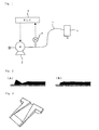
- the present invention relates to a coating apparatus for band-like applying a highly viscous material to an object, which comprises at least a hose, a pump and a coating gun having a slit nozzle, and preferably to a coating apparatus, which feeds a highly viscous material to a coating gun 3 through a hose 1 and a pump 2, and then, band-like applies the highly viscous material to an object from the slit nozzle of the coating gun 3, said coating apparatus being characterized in that
- Examples of the highly viscous material to be used in the present invention may include not only the above-described coat type metal sheet-reinforcing material but also general-use adhesives, coatings, sealing materials, coating materials, soundproof materials, damping materials, etc.
- the coat type metal sheet-reinforcing material for example, reinforcing materials comprising epoxy resins and polyurethane resins as main components as disclosed in JP-A-2002-226995 and JP-A-2003-127897 are exemplified.
- a reinforcing material comprising a liquid epoxy, a latent curing agent and a specific amount (20 to 50% by weight) of an inorganic filler in an aspect ratio (L/D) of 5 or more is preferable as the highly viscous material to be used in the present invention.
- Examples of the metal sheet of the automobile body to be coated with the above-described coat type metal sheet-reinforcing material include a SPC steel sheet, a steel sheet electroplated with zinc, a steel sheet plated with molten zinc, a steel sheet surface-treated with an organic agent, a steel sheet plated with an alloyed zinc, a steel sheet plated with a zinc-nickel alloy, a steel sheet plated with a tin-lead alloy, a cationic type electrodeposited steel sheet, an aluminum sheet, a magnesium sheet, etc.
- a coating apparatus essentially comprises a hose 1 (preferably a heat hose for feeding a highly viscous material generally under heating at a temperature of 35 to 60°C) which is connected to a feeder (not shown) for a highly viscous material such as a coat type metal sheet-reinforcing material (hereinafter simply referred to as a reinforcing material) so as to feed the reinforcing material; a pump 2; and a coating gun 3 having a slit nozzle (not shown).
- a hose 1 preferably a heat hose for feeding a highly viscous material generally under heating at a temperature of 35 to 60°C
- a feeder not shown
- a highly viscous material such as a coat type metal sheet-reinforcing material (hereinafter simply referred to as a reinforcing material) so as to feed the reinforcing material
- a pump 2 and a coating gun 3 having a slit nozzle (not shown).
- the reinforcing material kept being heated is band-like applied from the slit nozzle to the metal sheet of an automobile body.
- a robot for automatic coating.
- an optionally selected pump capable of feeding the highly viscous material may be used, and preferable examples of such a pump include constant flow pumps such as a gear pump, a plunger (or piston) pump, a rotary pump, a snake pump and the like.
- a gas injector which is one of the important features of the present invention and which is attached to the coating gun 3 to inject a gas to the band-like applied reinforcing material to thereby pressure-adhere the reinforcing material to the metal sheet so that the reinforcing material can be firmly fixed on the metal sheet of the automobile body.
- the gas to be used is preferably an air since it can be commonly used. It is also possible to use a heated or cooled air, a dried air or an inert gas such as nitrogen other than the air.
- the injector include, but not particularly limited to, devices capable of injecting compressed gases, devices capable of injecting gases by feeding the gases with propellers or fans, etc. Above all, a device capable of injecting a compressed air is the most preferable.
- the injecting angle for the gas is preferably from 15 to 85°, particularly from 30 to 60°, relative to the coating nozzle.
- the injecting pressure for the gas is preferably from 0.5 to 5 Kgf/cm 2 (from 0.05 to 0.49 MPa), particularly from 1 to 4 Kgf/cm 2 (from 0.10 to 0.39 MPa).
- the injecting pressure is lower than 0.5 Kgf/cm 2 (0.05 MPa)
- the injecting pressure exceeds 5 Kgf/cm 2 (0.49 MPa)
- the highly viscous material tends to deform.
- the precompression control mechanism comprises at least a controller 5 for the pump, such as a programmable logic controller (or PLC), and preferably further includes a pressure transmitter 4 which measures a pressure inside the hose 1 on the discharge side of the pump 2 when the application of the reinforcing material is started.
- a controller 5 for the pump such as a programmable logic controller (or PLC)
- PLC programmable logic controller
- the controller for the pump to be used in the present invention functions to read the value of a pressure inside the hose on the discharge side of the pump or the value of an output from a servo amplifier load monitor described later, for a calculating operation and to output a signal for controlling the actuation of the pump in order to adjust the inner pressure of the hose to a precompression target value.
- an example of the controller is a PLC, while, other than this means, a control panel may be used as the controller for the pump, when a coating robot is used (in case where the pump and the coating robot which are driven by servo motors, respectively, and which are provided by the same manufacturer are used in combination).
- the pressure value measured by the pressure transmitter 4 is fed to the controller 5, in which the pressure value is compared with a preset precompression target value to evaluate whether the pressure value is larger or smaller than the precompression target value.
- a reverse rotation signal, when larger than the target value, or a normal rotation signal, when smaller than the target value, is fed from the controller 5 to the constant flow pump 2, and the constant flow pump 2 is actuated for normal rotation or reverse rotation at a preset speed.
- an operation signal from the controller 5 to the constant flow pump 2 is stopped. In this way, the automatic switching operation of the constant flow pump 2 can be performed in response to the instruction from the controller 5.
- the hose 1 is preferably a heat hose capable of heating the highly viscous material to a constant temperature within a range of from 35 to 60°C.
- the use of the heat hose makes it possible to keep constant the viscosity of the highly viscous material and makes it hard for the coating amount to be influenced by a temperature of an external atmosphere. It also becomes possible to lower the viscosity of the viscous material so that the load on the constant flow pump 2 can be decreased.
- the load motor function of a servo amplifier can be used in place of the above pressure gauge.
- This case also can constitute the precompression control mechanism according to the present invention.
- an output from the load monitor of the servo amplifier can be used as the index of the above-described pressure, and the term of "pressure" used in the present specification also means "an output from the load monitor".
- Fig. 2 shows coating states: one is a case (A) where no precompression control was not made at the start of coating, and the other is a case (B) where precompression control was made at the start of coating.
- the thickness of the end portion of the applied material increases, which is likely to induce a strain in an outer metal sheet.
- the precompression is low at the start of coating, the amount of the applied material becomes insufficient, which is likely to lead to failure in fixing of the applied material, with the result that stain due to the sagging of the material, failure in electrodeposition coating and further, formation of rust may be induced.
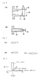
- Figs. 3 and 4 show an example of the special configuration of the slit nozzle to be used with the above-described coating gun 3.
- the configuration of the slit nozzle is other important feature of the present invention.
- Fig. 3 shows the internal structure of the slit nozzle divided into halves. The slit nozzle shown in Fig.
- a parallel nozzle which has a nozzle passage 13 (whose length L from the inlet 11 to the outlet 12 is preferably from 5 to 30 mm, more preferably from 8 to 20 mm) communicating with a radial introduction passage 10, and extending from the inlet 11 to the outlet 12 with a given parallel width W (preferably from 10 to 100 mm) and having a given clearance width S (preferably from 0.5 to 5 mm), as shown in Figs. 4(A) and 4(B) .
- the slit nozzle is preferably a heat nozzle capable of heating the highly viscous material to a constant temperature within a range of from 35 to 60°C similarly to the above-described hose.
- the slit opening of the nozzle may have a shape shown in Fig. 5(A) , a shape shown in Fig. 5(B) of which both end portions are partially cut off, or an elliptical shape shown in Fig. 5(C) . Particularly when the slit opening of the nozzle has a shape shown in Fig. 5(A) , a shape shown in Fig. 5(B) of which both end portions are partially cut off, or an elliptical shape shown in Fig. 5(C) . Particularly when the slit opening of the nozzle has a shape shown in Fig.
- the viscous material it is suitable to reapply the viscous material to parts of the applied viscous material (i.e., the cutoff portions or the end portions of the ellipse in the widthwise direction) at every one cycle (which is a period of time from the start of the first precompression to the start of the next precompression, in case where a cycle of the sequent steps of precompression, start of coating, completion of coating and precompression is repeated).
- the resultant applied material layer always can have a constant sectional shape which corresponds to the slit opening as shown in Fig. 5 .
- a reinforced metal sheet structure can be obtained by the present invention, that is, by applying a reinforcing material to a given object such as the metal sheet of an automobile body, and heating and curing the applied reinforcing material under predetermined baking conditions (generally at a temperature of from 140 to 220°C for from 10 to 60 minutes) to thereby form a reinforcing material layer having uniform thickness and shape.
- predetermined baking conditions generally at a temperature of from 140 to 220°C for from 10 to 60 minutes
- the resultant automatic coating apparatus was used in the following method.
- the metal sheet of an automobile body which was a SPC steel sheet, was used; and as a highly viscous material, "Penguin Stiffener #1190" (a coat type metal sheet-reinforcing material) manufactured by SUNSTAR ENGNEERING INC. was used.
- the pressure inside the heat hose 1 at the start of coating was adjusted to a precompression target value of 6 MPa, and then, the robot was caused to perform automatic coating.at a discharging rate of 1,200 cc/min. and at a coating rate of 400 mm/sec. and to inject a compressed air.
- the compressed air was injected in the manner shown in Fig. 6 .
- the compressed air adjusted to 3.5 Kgf/cm 2 (0.34 MPa) was injected through an air nozzle ("Typhoon Jet" having an external size of 38 mm X 65 mm X 8 mm, manufactured by H. Ikeuchi & Co., Ltd.) attached at an angle of 45° to the slit nozzle which applied the highly viscous material to the object in the arrow head direction, to thereby fix the coat type metal sheet-reinforcing material to the metal sheet of the automobile body.
- the applied reinforcing material was heated and cured under a baking condition of 170°C for 20 minutes to form an uniform and normal reinforcing material layer.
- the reinforced metal sheet structure for the automobile body was obtained.
Landscapes
- Physics & Mathematics (AREA)
- Fluid Mechanics (AREA)
- Coating Apparatus (AREA)
- Application Of Or Painting With Fluid Materials (AREA)
Applications Claiming Priority (1)
| Application Number | Priority Date | Filing Date | Title |
|---|---|---|---|
| PCT/JP2005/016838 WO2007032060A1 (ja) | 2005-09-13 | 2005-09-13 | 高粘度材料の塗布装置 |
Publications (2)
| Publication Number | Publication Date |
|---|---|
| EP1925369A1 true EP1925369A1 (de) | 2008-05-28 |
| EP1925369A4 EP1925369A4 (de) | 2014-01-15 |
Family
ID=37864666
Family Applications (1)
| Application Number | Title | Priority Date | Filing Date |
|---|---|---|---|
| EP05783180.2A Withdrawn EP1925369A4 (de) | 2005-09-13 | 2005-09-13 | Auftragsvorrichtung zur beschichtung mit hochviskosem material |
Country Status (6)
| Country | Link |
|---|---|
| US (1) | US20100279127A1 (de) |
| EP (1) | EP1925369A4 (de) |
| JP (1) | JPWO2007032060A1 (de) |
| KR (1) | KR101212431B1 (de) |
| CA (1) | CA2621551C (de) |
| WO (1) | WO2007032060A1 (de) |
Cited By (5)
| Publication number | Priority date | Publication date | Assignee | Title |
|---|---|---|---|---|
| US20100069877A1 (en) * | 2008-09-10 | 2010-03-18 | Smith Gregory A | Apparatus and method to dispense hpc-based viscous liquids into porous substrates, e.g., continuous web-based process |
| DE102008047234A1 (de) * | 2008-09-12 | 2010-03-25 | Henkel Ag & Co. Kgaa | Reparaturdüse |
| CN103464336A (zh) * | 2013-08-26 | 2013-12-25 | 蚌埠市宏威滤清器有限公司 | 滤清器涂胶机 |
| WO2016050085A1 (zh) * | 2014-09-30 | 2016-04-07 | 京东方科技集团股份有限公司 | 用于涂布封框胶的涂布装置、涂布系统及涂布方法 |
| CN105834070A (zh) * | 2016-06-20 | 2016-08-10 | 京东方科技集团股份有限公司 | 一种点胶装置 |
Families Citing this family (13)
| Publication number | Priority date | Publication date | Assignee | Title |
|---|---|---|---|---|
| ES2961277T3 (es) | 2011-04-11 | 2024-03-11 | Nordson Corp | Sistema, boquilla y procedimiento para revestir hebras elásticas |
| USD671970S1 (en) | 2012-04-10 | 2012-12-04 | Nordson Corporation | Nozzle for applying adhesive to strands |
| US9682392B2 (en) | 2012-04-11 | 2017-06-20 | Nordson Corporation | Method for applying varying amounts or types of adhesive on an elastic strand |
| US9034425B2 (en) | 2012-04-11 | 2015-05-19 | Nordson Corporation | Method and apparatus for applying adhesive on an elastic strand in a personal disposable hygiene product |
| USD673594S1 (en) | 2012-06-18 | 2013-01-01 | Nordson Corporation | Nozzle for applying adhesive to strands |
| US10422614B2 (en) * | 2012-09-14 | 2019-09-24 | Henkel IP & Holding GmbH | Dispenser for applying an adhesive to a remote surface |
| JP6308789B2 (ja) * | 2014-01-29 | 2018-04-11 | 兵神装備株式会社 | ノズル、塗布装置、及び流動物の塗布方法 |
| DE102014213401A1 (de) | 2014-03-28 | 2015-10-01 | Sms Group Gmbh | Vorrichtung zum Aufbringen und Absaugen von Betriebsstoffen im Einlauf von Kaltwalzanlagen |
| DE102017119439A1 (de) * | 2017-08-24 | 2019-02-28 | Khs Gmbh | Verfahren zum Steuern der Menge eines auf einen Träger aufzubringenden Klebemittels |
| CN113165007A (zh) * | 2018-07-16 | 2021-07-23 | 塞姆产品股份有限公司 | 组合物涂抹器尖端和仪器 |
| KR20240154352A (ko) * | 2023-04-18 | 2024-10-25 | 에스케이온 주식회사 | 디스펜싱된 점성유체의 검사와 리페어를 수행하는 장치 및 방법 |
| KR102657373B1 (ko) * | 2023-09-14 | 2024-04-12 | 민성환 | 산업용 제조 설비의 구동을 위한 회로 설계 자동화 및 이에 의한 제어 방법, 장치 및 시스템 |
| EP4527507A1 (de) * | 2023-09-21 | 2025-03-26 | Infotech, AG | Abgabesystem, abgabekopf und verfahren zum aufbringen eines klebematerials |
Family Cites Families (19)
| Publication number | Priority date | Publication date | Assignee | Title |
|---|---|---|---|---|
| FI68536C (fi) * | 1983-10-17 | 1985-10-10 | Waertsilae Oy Ab | Luftknivsbestrykare |
| JPS6274110A (ja) * | 1985-09-27 | 1987-04-04 | Toyota Motor Corp | 粘性流体の流量制御方法及び装置 |
| JPH0466158A (ja) * | 1990-07-05 | 1992-03-02 | San Tool:Kk | 塗布装置におけるノズル装置 |
| EP0477965A3 (en) * | 1990-09-28 | 1992-05-27 | National Starch And Chemical Investment Holding Corporation | Hot-melt applicator |
| CA2098784A1 (en) * | 1992-07-08 | 1994-01-09 | Bentley Boger | Apparatus and methods for applying conformal coatings to electronic circuit boards |
| JP3423077B2 (ja) * | 1993-08-25 | 2003-07-07 | ダブリュ・アール・グレイス・アンド・カンパニー・コネテイカット | 版面の製造方法 |
| US5478224A (en) * | 1994-02-04 | 1995-12-26 | Illinois Tool Works Inc. | Apparatus for depositing a material on a substrate and an applicator head therefor |
| BE1008074A3 (nl) * | 1994-02-14 | 1996-01-09 | Dsm Nv | Werkwijze voor het op continue wijze bedekken van een strookvormig materiaal met een thermohardende verf. |
| JPH08196969A (ja) * | 1995-01-25 | 1996-08-06 | Honda Motor Co Ltd | 塗布ノズル |
| DE19714029C2 (de) * | 1997-04-04 | 1999-06-10 | Bargen Rudolf Von | Auftragskopf |
| JP2000126665A (ja) * | 1998-10-23 | 2000-05-09 | Sekisui Chem Co Ltd | 接着剤自動塗布装置及び接着剤自動塗布方法 |
| JP3547404B2 (ja) * | 2001-02-01 | 2004-07-28 | サンスター技研株式会社 | 塗布型板金補強材組成物 |
| JP2002273299A (ja) * | 2001-03-22 | 2002-09-24 | Fuji Photo Film Co Ltd | 塗布装置および塗布方法 |
| JP4166465B2 (ja) * | 2001-12-14 | 2008-10-15 | 三菱化学株式会社 | 塗布装置、塗布方法、および塗布基板の製造方法 |
| JP2004148167A (ja) | 2002-10-29 | 2004-05-27 | Nordson Corp | 粘性流体材料の塗布方法及び装置 |
| JP4653088B2 (ja) * | 2003-07-14 | 2011-03-16 | ノードソン コーポレーション | 個別量の粘性材料を分配するための装置及び方法 |
| DE10337768A1 (de) * | 2003-08-14 | 2005-03-17 | Nordson Corporation, Westlake | Düsen- und Filteranordnung sowie System zum Auftragen von Fluid mit festen Partikeln auf ein Substrat |
| KR100708037B1 (ko) * | 2003-12-24 | 2007-04-16 | 마츠시타 덴끼 산교 가부시키가이샤 | 유체공급노즐, 기판처리장치 및 기판처리방법 |
| JP2005262011A (ja) * | 2004-03-16 | 2005-09-29 | Sunstar Eng Inc | 高粘度材料の塗布装置 |
-
2005
- 2005-09-13 CA CA 2621551 patent/CA2621551C/en not_active Expired - Fee Related
- 2005-09-13 KR KR1020087006489A patent/KR101212431B1/ko not_active Expired - Fee Related
- 2005-09-13 US US11/991,783 patent/US20100279127A1/en not_active Abandoned
- 2005-09-13 WO PCT/JP2005/016838 patent/WO2007032060A1/ja not_active Ceased
- 2005-09-13 JP JP2007535343A patent/JPWO2007032060A1/ja active Pending
- 2005-09-13 EP EP05783180.2A patent/EP1925369A4/de not_active Withdrawn
Cited By (8)
| Publication number | Priority date | Publication date | Assignee | Title |
|---|---|---|---|---|
| US20100069877A1 (en) * | 2008-09-10 | 2010-03-18 | Smith Gregory A | Apparatus and method to dispense hpc-based viscous liquids into porous substrates, e.g., continuous web-based process |
| DE102008047234A1 (de) * | 2008-09-12 | 2010-03-25 | Henkel Ag & Co. Kgaa | Reparaturdüse |
| DE102008047234B4 (de) * | 2008-09-12 | 2018-12-06 | Henkel Ag & Co. Kgaa | Reparaturdüse und Reparatursystem |
| CN103464336A (zh) * | 2013-08-26 | 2013-12-25 | 蚌埠市宏威滤清器有限公司 | 滤清器涂胶机 |
| WO2016050085A1 (zh) * | 2014-09-30 | 2016-04-07 | 京东方科技集团股份有限公司 | 用于涂布封框胶的涂布装置、涂布系统及涂布方法 |
| US9700914B2 (en) | 2014-09-30 | 2017-07-11 | Boe Technology Group Co., Ltd. | Coating device, system and method for sealant |
| CN105834070A (zh) * | 2016-06-20 | 2016-08-10 | 京东方科技集团股份有限公司 | 一种点胶装置 |
| CN105834070B (zh) * | 2016-06-20 | 2019-01-18 | 京东方科技集团股份有限公司 | 一种点胶装置 |
Also Published As
| Publication number | Publication date |
|---|---|
| JPWO2007032060A1 (ja) | 2009-03-19 |
| KR101212431B1 (ko) | 2012-12-13 |
| CA2621551A1 (en) | 2007-03-22 |
| KR20080048484A (ko) | 2008-06-02 |
| US20100279127A1 (en) | 2010-11-04 |
| CA2621551C (en) | 2012-10-23 |
| WO2007032060A1 (ja) | 2007-03-22 |
| EP1925369A4 (de) | 2014-01-15 |
Similar Documents
| Publication | Publication Date | Title |
|---|---|---|
| CA2621551C (en) | Coating apparatus for highly viscous material | |
| RU2755990C2 (ru) | Способ нанесения содержащего серу герметизирующего состава, устройство для него, соответственно обработанный аэрокосмический летательный аппарат и его применение | |
| US6540835B2 (en) | Scratch resistant coating application system for vehicle | |
| US10933584B2 (en) | Additive manufacturing system having dynamically variable matrix supply | |
| CA1258407A (en) | Process and apparatus for application of a curable material to an article | |
| US4682711A (en) | Method and apparatus for sealing welded seams of automobiles | |
| WO2001007230A1 (en) | Method of forming coating on inner surfaces of metal mold | |
| EP1262244B1 (de) | Beschichtungsdüse sowie Verfahren und Vorrichtung zum Beschichten eines Kompressor-Kolben mit derselben | |
| CN111936292A (zh) | 橡胶包覆帘线制造装置以及橡胶包覆帘线制造方法 | |
| CA2128837C (en) | Method and device for coating a body rotating about an axis | |
| JP2005262011A (ja) | 高粘度材料の塗布装置 | |
| US20080240842A1 (en) | Glass sealant applicator nozzle and method of use thereof | |
| CN101257978A (zh) | 高粘度材料的涂敷装置 | |
| SE513660C2 (sv) | Förfarande för framställning av blad försedda med mjuk kantbeläggning | |
| JP5606183B2 (ja) | ボルト連結部の塗装装置および塗装方法 | |
| JP5310475B2 (ja) | ワックス塗布装置および塗布方法 | |
| KR102478628B1 (ko) | 일체형 알루미늄 루프랙 제조방법 | |
| GB2615181A (en) | Application and method for application of a fluid material | |
| JP2002527226A (ja) | コンプライアンス機構 | |
| KR102241722B1 (ko) | 발포 패드 원료 도포 건, 발포 패드 원료 도포 장치, 및 발포 패드 원료 도포 방법 | |
| KR100862054B1 (ko) | 개선된 코팅액 펌핑장치 및 이를 구비한 슬릿 다이 및테이블 코팅 장치 | |
| EP1717349A1 (de) | Schutzfilmmittel und verfahren zur herstellung eines schutzfilms | |
| US6423371B1 (en) | Apparatus and method for forming a bonding on a tapered part | |
| KR100482591B1 (ko) | 바디패널 보강용 실러 도포장치 및 그 제어방법 | |
| KR100767899B1 (ko) | 실러 도포장치용 정량 토출장치 |
Legal Events
| Date | Code | Title | Description |
|---|---|---|---|
| PUAI | Public reference made under article 153(3) epc to a published international application that has entered the european phase |
Free format text: ORIGINAL CODE: 0009012 |
|
| 17P | Request for examination filed |
Effective date: 20080306 |
|
| AK | Designated contracting states |
Kind code of ref document: A1 Designated state(s): DE ES FR GB NL SE |
|
| DAX | Request for extension of the european patent (deleted) | ||
| RBV | Designated contracting states (corrected) |
Designated state(s): DE ES FR GB NL SE |
|
| A4 | Supplementary search report drawn up and despatched |
Effective date: 20131218 |
|
| RIC1 | Information provided on ipc code assigned before grant |
Ipc: B05C 5/02 20060101ALI20131212BHEP Ipc: B05C 5/00 20060101AFI20131212BHEP Ipc: B05C 11/10 20060101ALI20131212BHEP Ipc: B05C 9/12 20060101ALI20131212BHEP Ipc: B05D 1/26 20060101ALI20131212BHEP Ipc: B05D 7/14 20060101ALI20131212BHEP Ipc: B05C 11/06 20060101ALI20131212BHEP |
|
| STAA | Information on the status of an ep patent application or granted ep patent |
Free format text: STATUS: THE APPLICATION IS DEEMED TO BE WITHDRAWN |
|
| 18D | Application deemed to be withdrawn |
Effective date: 20140722 |