EP1923869A2 - Aufzeichnungsleistungskorrekturverfahren sowie Aufzeichnungs- und Wiedergabevorrichtung für einen optischen Datenträger - Google Patents
Aufzeichnungsleistungskorrekturverfahren sowie Aufzeichnungs- und Wiedergabevorrichtung für einen optischen Datenträger Download PDFInfo
- Publication number
- EP1923869A2 EP1923869A2 EP07254408A EP07254408A EP1923869A2 EP 1923869 A2 EP1923869 A2 EP 1923869A2 EP 07254408 A EP07254408 A EP 07254408A EP 07254408 A EP07254408 A EP 07254408A EP 1923869 A2 EP1923869 A2 EP 1923869A2
- Authority
- EP
- European Patent Office
- Prior art keywords
- recording
- recording power
- reproduction
- signal
- data recording
- Prior art date
- Legal status (The legal status is an assumption and is not a legal conclusion. Google has not performed a legal analysis and makes no representation as to the accuracy of the status listed.)
- Withdrawn
Links
- 238000012937 correction Methods 0.000 title claims abstract description 80
- 230000003287 optical effect Effects 0.000 title claims abstract description 68
- 238000000034 method Methods 0.000 title claims abstract description 43
- 238000001514 detection method Methods 0.000 claims abstract description 77
- 238000011156 evaluation Methods 0.000 claims description 67
- 238000004364 calculation method Methods 0.000 claims description 11
- 238000012545 processing Methods 0.000 abstract description 23
- 238000003672 processing method Methods 0.000 abstract description 4
- 230000008859 change Effects 0.000 description 16
- 230000000875 corresponding effect Effects 0.000 description 13
- 238000010586 diagram Methods 0.000 description 12
- 238000013459 approach Methods 0.000 description 8
- 230000004044 response Effects 0.000 description 7
- 239000010410 layer Substances 0.000 description 5
- 238000007476 Maximum Likelihood Methods 0.000 description 4
- 238000012360 testing method Methods 0.000 description 4
- 230000006870 function Effects 0.000 description 3
- 230000003247 decreasing effect Effects 0.000 description 2
- 238000005259 measurement Methods 0.000 description 2
- 230000005855 radiation Effects 0.000 description 2
- 230000009467 reduction Effects 0.000 description 2
- 230000007704 transition Effects 0.000 description 2
- QNRATNLHPGXHMA-XZHTYLCXSA-N (r)-(6-ethoxyquinolin-4-yl)-[(2s,4s,5r)-5-ethyl-1-azabicyclo[2.2.2]octan-2-yl]methanol;hydrochloride Chemical compound Cl.C([C@H]([C@H](C1)CC)C2)CN1[C@@H]2[C@H](O)C1=CC=NC2=CC=C(OCC)C=C21 QNRATNLHPGXHMA-XZHTYLCXSA-N 0.000 description 1
- 238000003491 array Methods 0.000 description 1
- 238000006243 chemical reaction Methods 0.000 description 1
- 230000002596 correlated effect Effects 0.000 description 1
- 230000000694 effects Effects 0.000 description 1
- 230000001678 irradiating effect Effects 0.000 description 1
- 239000011241 protective layer Substances 0.000 description 1
- 238000010187 selection method Methods 0.000 description 1
- 239000004065 semiconductor Substances 0.000 description 1
- 230000035945 sensitivity Effects 0.000 description 1
- 239000000758 substrate Substances 0.000 description 1
Images



Classifications
-
- G—PHYSICS
- G11—INFORMATION STORAGE
- G11B—INFORMATION STORAGE BASED ON RELATIVE MOVEMENT BETWEEN RECORD CARRIER AND TRANSDUCER
- G11B7/00—Recording or reproducing by optical means, e.g. recording using a thermal beam of optical radiation by modifying optical properties or the physical structure, reproducing using an optical beam at lower power by sensing optical properties; Record carriers therefor
- G11B7/12—Heads, e.g. forming of the optical beam spot or modulation of the optical beam
- G11B7/125—Optical beam sources therefor, e.g. laser control circuitry specially adapted for optical storage devices; Modulators, e.g. means for controlling the size or intensity of optical spots or optical traces
- G11B7/126—Circuits, methods or arrangements for laser control or stabilisation
- G11B7/1263—Power control during transducing, e.g. by monitoring
-
- G—PHYSICS
- G11—INFORMATION STORAGE
- G11B—INFORMATION STORAGE BASED ON RELATIVE MOVEMENT BETWEEN RECORD CARRIER AND TRANSDUCER
- G11B7/00—Recording or reproducing by optical means, e.g. recording using a thermal beam of optical radiation by modifying optical properties or the physical structure, reproducing using an optical beam at lower power by sensing optical properties; Record carriers therefor
- G11B7/004—Recording, reproducing or erasing methods; Read, write or erase circuits therefor
- G11B7/0045—Recording
Definitions
- the present invention relates to a correction technique of recording power during data recording into an optical disk.
- An optical disk such as CD-R (write-once type CD), DVD ⁇ R (write-once type DVD), HD-DVD-R (write-once type HD-DVD), or BD-R (write-once type Blu-ray disc) has a structure where a recording layer, reflective layer, and protective layer as needed are formed on one surface of an optical transparency disk substrate. Moreover, spiral or concentric-circle grooves called grooves are formed on the one surface on which the recording layer and the reflective layer are formed, and a portion between adjacent grooves is formed to be a convex portion called land.
- a recording laser beam is irradiated to the recording layer over the grooves with the beam tracking along the grooves by a recording and reproduction device for optical disk, thereby pits are formed so that recording is performed.
- the pits have a length nT (bit length between respective reference channel clocks is assumed to be T, and length of integral multiples of n of the bit length is assumed to be nT), and portions between the pits (hereinafter, called spaces) also have a length nT, arrays of them are irradiated with a laser beam for reproduction, and a reflected beam is converted into a reproduction signal, so that reproduction is performed.
- the recording and reproduction device for optical disk that performs such recording or reproduction is designed so as to meet a recording condition that is varied every time when recording is performed into each optical disk due to a drive, an optical disk (sometimes called media), recording velocity and the like.
- the recording and reproduction device for optical disk employs a technique for optimally setting laser radiation intensity (hereinafter, called recording power).
- recording power a technique for optimally setting laser radiation intensity
- a device is given as such a technique, which uses OPC (Optimal Power Calibration) as a selection method.
- OPC Optimal Power Calibration
- test recording is performed before data recording into a test area (Power Calibration Area) of a recording disk while changing output of a recording laser beam.
- each of results of the test recording is compared to a result based on a previously registered, initial condition, and therethrough best recording power providing excellent recording quality is selected from the results, and set. Recording is performed into a data recording area of the optical disk using the set recording laser beam with the best recording power.
- a value of ⁇ which is one type of asymmetry being an evaluation index showing asymmetry of a waveform formed by reproducing a recording waveform, is calculated from change in recording and reproduction signal when a recording power condition is changed, and the value of ⁇ is determined so as to be equal or close to a target value, so that best recording power is obtained for best recording correction.
- a device employing a technique in which, to cope with change in characteristic (sensitivity) depending on thickness variation from inner circumference to outer circumference of an optical disk or influence of a warp of the optical disk, a return beam (WRF) to a spot of a recording laser beam is detected during data recording, or a sub-spot provided near a main spot is detected by using optical diffraction during the data recording, thereby the value of ⁇ as above, jitter (fluctuation in a time axis direction of a digital signal) or a value of an evaluation index in a correlation with the jitter is acquired so that the recording power condition is optimized in real time for the optical disk itself or the recording and reproduction device for optical disk.
- ROPC Running Optimal Power Calibration
- a device is disclosed as a simple approach of the above technique, which employs a technique (WOPC: Walking Optical Power Calibration) in which during data recording from inner circumference to outer circumference of an optical disk, recording operation is temporarily stopped at a predetermined position on the optical disk, and data area, to which recording is performed immediately before such operation stop, is subjected to reproduction, thereby the value of ⁇ , jitter, or the value of the evaluation index in a correlation with the jitter is acquired in order to optimize the recording power condition.
- WOPC Walking Optical Power Calibration
- the usual techniques have a problem that they cannot cope with an optical disk for high density recording and reproduction, in which the value of ⁇ or asymmetry as an evaluation index being similar to ⁇ but calculated by a different method is not in a correlation with recording power, consequently the techniques cannot appropriately correct recording power.
- the invention was made noticing the above points, and an object of the invention is to provide a correction technique of recording power that can cope with even the recording and reproduction system for optical disk for high density optical recording and reproduction (hereinafter, called high density optical recording and reproduction device).
- Another object of the invention is to provide a technique that enables appropriate correction of recording power using a novel evaluation index.
- Still another object of the invention is to provide a technique for updating correction data of recording power such that recording power of a high density optical recording and reproduction device can be more accurately corrected.
- a recording power correction method includes a step of performing data recording into an optical disk, then temporarily stopping the data recording, and reproducing a certain period in the data recording, and detecting a reproduction signal caused by the reproduction; a step of specifying a detection pattern including a predetermined code from the reproduction signal that was detected; a step of detecting a signal state in the reproduction signal corresponding to the detection pattern; and a step of determining a correction direction and amount of correction of recording power in the data recording based on the signal state that was detected, and a reference state specified from the detection pattern.
- processing is performed on the basis of the detection pattern in this way, thereby even a high density optical recording and reproduction device employing the PRML signal processing method can be appropriately corrected in recording power.
- the predetermined code is sometimes a code having a length nearest to effective diameter of a spot of a laser beam for reproduction. While described in detail below, by noticing such a code, the technical approach can cope with an optical disk in which ⁇ or asymmetry is not correlated with recording power.
- the reference state is sometimes a theoretical value corresponding to the detection pattern. Moreover, the reference state is sometimes determined based on data obtained in pre-adjustment of the recording power performed before the data recording.
- the amount of correction of the recording power is sometimes a predetermined fixed amount. That is, only the correction direction is determined in the determination step, and the amount of correction is fixed.
- the determination step may include a step of calculating the amount of correction of the recording power based on difference between the signal state and the reference state, and a predetermined relationship between the signal state and the reference state.
- the amount of correction is calculated on the basis of a novel evaluation index of difference between the signal state and the reference state.
- the difference between the signal state and the reference state may include information on polarity (for example, plus or minus).
- the predetermined relationship between the signal state and the reference state may be specified by a relational expression between the signal state and the reference state or a table showing that relational expression, which is obtained in pre-adjustment of the recording power performed before the data recording.
- the signal state and the reference state are sometimes specified by an amplitude level of the reproduction signal respectively.
- they are sometimes specified by information of length between two points at which a certain slice level intersects with the reproduction signal in an area where difference between the signal state and the reference state appears.
- a recording power correction method includes a step of performing data recording into an optical disk, then temporarily stopping the data recording, and reproducing a certain period in the data recording, and detecting a reproduction signal caused by the reproduction; a step of specifying a detection pattern including a code having a length nearest to effective diameter of a spot of a laser beam for reproduction from the reproduction signal that was detected; a step of detecting a signal state in the reproduction signal corresponding to the detection pattern; and a correction step of performing correction of recording power in the data recording based on the signal state that was detected.
- the code having the length nearest to the effective diameter of the spot of the laser beam for reproduction is noticed, and correction of recording power is performed using the novel evaluation index, thereby recording power can be more appropriately corrected.
- the signal state may be an amplitude level.
- the correction step may include a step of calculating a value of asymmetry according to the code having the length nearest to the effective diameter of the spot of the laser beam for reproduction. A novel evaluation index is introduced in this way, thereby the correction amount of recording power can be appropriately set.
- the signal state may be an amplitude level.
- the correction step may include a step of calculating a value of a numerical aperture or amplitude level variation according to the code having the length nearest to the effective diameter of the spot of the laser beam for reproduction. A novel evaluation index may be introduced in this way.
- a recording power correction method includes a step of performing data recording into an optical disk, then temporarily stopping the data recording, and reproducing a certain period in the data recording, and detecting a reproduction signal caused by the reproduction; a step of specifying a detection pattern including a predetermined code from the reproduction signal that was detected; a step of detecting a signal state in the reproduction signal corresponding to the detection pattern; an evaluation value calculation step of calculating an evaluation value based on the signal state that was detected; and a step of using recording power in the data recording and the evaluation value to correct a correction expression or correction table of the recording power.
- the correction expression or correction table for the recording power is corrected in this way, thereby correction of the correction expression or the correction table of the recording power is advanced every time when the recording power correction method according to the third aspect of the invention is carried out, and correction data of the recording power can be updated such that the recording power can be more accurately corrected, consequently appropriate data recording is performed.
- a reference state specified from the detection pattern may be further used to calculate the evaluation value in the evaluation value calculation step.
- the evaluation value may be a value of asymmetry, a numerical aperture, or amplitude level variation according to a code having a length nearest to effective diameter of a spot of a laser beam for reproduction.
- the evaluation value may be a value based on difference between the detected signal state and the reference state specified from the detection pattern. Moreover, the evaluation value may be a length between two points at which a certain slice level intersects with the reproduction signal.
- a program for allowing a processor to execute the recording power correction method of the invention can be produced. That program is stored in a storage medium or a storage device such as an optical disk including flexible disk or CD-ROM, or magneto-optical disk, a semiconductor memory, and a hard disk. Moreover, the program is sometimes distributed by a digital signal via a network. Data during processing are temporarily stored in a storage device such as a memory of the processor.
- FIG. 1 A method has been used, in which change in value of an evaluation index such as asymmetry or ⁇ is used to evaluate recording power.
- an evaluation index such as asymmetry or ⁇
- a condition where the index is not in a correlation with the recording power may occur at a high possibility in an optical disk for high density optical recording and reproduction (optical disk according to the Blu-ray standard or the HD-DVD standard, hereinafter, simply called "high density optical disk").
- a vertical axis shows a value (level) of asymmetry
- a horizontal axis shows recording power
- plotted data show how asymmetry changes when recording power is changed.
- the asymmetry described herein is a value showing asymmetry of an eye pattern as ⁇ , and an evaluation index obtained as follows: when an HF signal is obtained from recording data read by an optical pickup in an evaluation circuit system in DC (direct current) connection, and it is assumed that a maximum amplitude level at a space side is I2S, a minimum amplitude level at a pit side is I2P, a minimum amplitude level at a space side is 18S, and a maximum amplitude level at a pit side is I8P, the evaluation index is obtained by the following expression.
- a new evaluation index for appropriately evaluating intensity of recording power is investigated.
- a detection pattern (appearance pattern of marks and spaces) for detecting change in recording condition due to recording power is considered.
- Fig. 2 shows change in amplitude level of each code (mark of length nT) in the case that recording power is changed. That is, in Fig. 2 , a vertical axis shows an amplitude level in a form of a signal voltage level, and a horizontal axis shows a data symbol (n of the mark of length nT is an integer between 2 and 8 in the Blu-ray standard, and an integer between 2 and 11 in the HD-DVD standard).
- n of the mark of length nT is an integer between 2 and 8 in the Blu-ray standard, and an integer between 2 and 11 in the HD-DVD standard.
- the amplitude level reaches a peak level between 4T and 6T in any kind of recording power, and the relevant amplitude level is extremely slightly different from an amplitude level of a code having a length longer than the relevant length.
- a spot of the laser beam has an effective diameter ( ⁇ 0.4 ⁇ m).
- a signal voltage level as the amplitude level is changed in proportion to the mark length, and when the mark length is sufficiently larger than the effective diameter of the spot as shown in Fig. 3B , the signal voltage level is not significantly influenced by the mark length.
- change in length, width and depth of a mark is an amplitude variation factor in the case that effective diameter of a spot is longer than mark length
- change in length of a mark is not an amplitude variation factor
- only change in width and depth of a mark is an amplitude variation factor in the case that effective diameter of a spot is shorter than mark length.
- a value of the asymmetry of 2T8T which is calculated from an amplitude level of a mark of 2T in which effective diameter of a spot is longer than mark length, and an amplitude level of a mark of 8T in which effective diameter of a spot is shorter than mark length, becomes an index being not significantly changed with change in recording power.
- Fig. 4 shows summary of only change in minimum power and change in maximum power in the amplitude change model when recording power is changed as shown in Fig. 2 .
- a vertical axis shows an amplitude level
- a horizontal axis shows time and corresponding data symbols in proportion to time.
- a pulse for writing the corresponding code data is shown so as to be able to correspond to the amplitude change model.
- Fig. 4 as power is increased, more time is required before the amplitude level reaches the peak. For example, when power is low, the time before it reaches the peak requires only a short time corresponding to 4T. However, when power is high, it requires a time corresponding to 5T.
- the mark of 4T is most significantly subjected to influence of recording power on the relevant peak level. That is, recording power in forming the mark of 4T is in a correlation with the amplitude level in reproducing the mark of 4T in a manner that the recording power has influence on the amplitude level.
- Fig. 5 shows an ideal state transition chart of PR (1, 2, 2, 1) used in the Blu-ray standard.
- PR is abbreviation of partial response, and it shows imperfect frequency response, in which inter-symbol interference is remained, with respect to frequency response for achieving a distortionless condition, and relates to a signal processing method for covering reduction in signal quality for removing inter-symbol interference in combination with a technique of maximum likelihood decoding.
- an amplitude level of 4t mark is shown by an upward curve, and just reaches a peak value 6 of amplitude peak levels (levels of 0 to 6).
- Respective plots of amplitude levels of data samples as shown in Fig.
- Fig. 5 correspond to values given by converting ideal signals into amplitude levels, the ideal signals being obtained from profile values (1, 3, 5, 6, 5, 3, 1) given by calculating mark length of 4T according to the Viterbi algorithm at a condition of "Low to High".
- an amplitude level of the 3T mark does not reach the amplitude peak level as clear from Figs. 2 and 4 .
- the 4T mark is most influenced by recording power.
- a downward curve shows an ideal state transition in the case of a space of 4T. This shows that the amplitude level of the 4T mark is largely changed depending on recording power.
- profile values given by calculating the mark length of 4T according to the Viterbi algorithm at a condition of "High to Low” profile values of respective data samples of marks and spaces in Fig. 5 are interchanged.
- a code pattern is used as a detection pattern, which is centered at the 4T mark, and under influence of adjacent spaces, and a recording condition of the code pattern is grasped as a signal condition, thereby recording power can be adjusted.
- Each of code conditions before and after the 4T mark is desirably specified to be a space symbol being so long that inter-symbol interference does not have problematic influence on the space symbol, or specified to be, for example, a code condition of the 3T space or more so as to be not influenced by a code pattern.
- the code of the 4T mark is specified from effective diameter of a spot of a laser beam for reproduction for BD-R in the Blu-ray standard, and the 4T mark is not necessarily suitable in all cases.
- a code pattern is preferably used as a detection pattern, which is centered at the 5T mark, and under influence of adjacent spaces.
- Each of code conditions before and after the 5T mark is desirably specified to be a space symbol being so long that inter-symbol interference does not have problematic influence on the space symbol, or specified to be, for example, a code condition of the 4T space or more so as to be not influenced by a code pattern.
- Fig. 6 shows a functional block chart of a high density optical recording and reproduction device according to a first embodiment of the invention.
- the high density optical recording and reproduction device has an optical unit (PU) 1 for irradiating a laser beam to a high density optical disk 15 to perform the recording and reproduction; a pre-equalizer (Pre-EQ) 3 for performing equalization of a waveform so as to easily convert an electric signal from a photodetector included in the optical unit 1 into a digital signal in a subsequent step; ADC (Analog Digital Converter) 5 for converting an analog signal into a digital signal; an equalizer 7 that performs nonlinear equalization of a waveform for making amplitude of a shortest mark length to be close to amplitude of DVD or the like, that is, performs equalization of a binarized digital signal with a waveform, in which an amplitude level in a central position in a longitudinal direction of the 4T mark corresponds to a peak value, and values of amplitude levels, each
- a high density optical recording and reproduction device for example, since a shortest mark length of a pit recorded into a high density optical disk is 0.149 ⁇ m, which is short, 1/2.7 of that in the case of DVD, the mark length is close to a limit of optical resolution for an optical beam to be able to identify a pit. Moreover, when a pit row of a mark is reproduced using an optical beam, amplitude of a reproduction signal is reduced with decrease in mark length, and reduced to zero at the limit of resolution. Furthermore, in addition to such reduction in amplitude to zero, interference (called inter-symbol interference) occurs with adjacent marks in neighboring mark rows to be recorded, so that distortion appears in a reproduction signal. In consideration of such a special circumstance, the high density optical recording and reproduction device is configured to perform the PRML signal processing.
- the control part 11 has a code identification part 111 that relates output of the equalizer 7 (RF signal given by reproduction in which a waveform is nonlinearly equalized) to output (code data given by maximum likelihood decoding) of the Viterbi decoder 9; a detection instruction part 113 that specifically instructs detection of an amplitude level when the part 113 detects a previously set detection pattern based on code data from the code identification part 111, for example, detects appearance of a state of recorded medium in an amplitude level of 4T mark influenced by adjacent 3T spaces; a detection part 115 that performs detection processing of a signal state in the amplitude level to an RF signal from the code identification part 111 according to an instruction from the detection instruction part 113; and an operation part 117 that has a not-shown memory, and generates a reference state based on output from the detection part 115, performs operation described below, and performs setting for the recording waveform generation part 13.
- the operation part 117 may be achieved by a combination of a
- step S1 determination of laser radiation intensity (called recording power) for appropriately performing recording during recording, which is called power calibration, is carried out, and initial reference data are acquired (step S1).
- the operation part 117 of the control part 111 allows a predetermined pattern to be written at several kinds of recording power into a test write area provided, for example, on the most inner circumferential area of the optical disk 15, and determines initial recording power to the relevant optical disk 15 based on a predetermined reference. Since a specific procedure of such processing is disclosed in various literatures, and it is not a major part in the embodiment, further description of the processing is omitted.
- the detection part 115 performs specifying of the predetermined codes of "3T space, 4T mark, and 3T space" as a detection pattern to the RF signal from the code identification part 111 in response to the detection instruction, and detects a signal state of the pattern as an amplitude level of a 4t mark influenced by 3T spaces before and after the 4t mark.
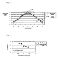
- Fig. 8 Processing by the detection part 115 is described using Fig. 8 with a relationship between plotted values given by calculating an amplitude level of a signal of the 4T mark length influenced by 3T spaces before and after the 4t mark in detected signals, and profile values in an ideal state of an ideal signal of the 4T mark length, the ideal state being calculated according to the Viterbi algorithm.
- a vertical axis shows the amplitude level
- a horizontal axis shows a data sample number.
- the detection part 115 detects amplitude levels (data sample values), for example, at seven points of detection signal b shown in Fig. 8 with a peak as a center, and outputs the amplitude levels to the operation part 117.
- a span of length to be detected may be wider than a span of code length of a detection object to take more data samples if it is without departing from the gist of the invention, for example, the span of length to be detected may be wider than a span corresponding to 4T in the case of a 4T mark, or may be wider than a span corresponding to 5T, for example, a span corresponding to 8T in the case of the 5T mark.
- the operation part 117 specifies three points centered at the peak as an operation sample, the points being enclosed by a dotted line A in Fig. 8 , and calculates an evaluation value ProfileGap by the following expression.
- the three points are illustrative only.
- D(x) indicates, for example, values of the detection signal b shown in Fig. 8 as data sample values
- R(x) indicates values of the ideal signal a shown in Fig. 8
- a symbol x shows a data profile number (data sample number)
- symbol a shows an operation beginning data profile number
- symbol n shows the number of data samples.
- a is 3, and n is 7.
- gaps between the detection signal b and the ideal signal a are summed at the three points enclosed by the dotted line A, and when the detection signal b is lower than the ideal signal a as shown in Fig. 8 , recording power is insufficient, and conversely, when the detection signal b is higher than the ideal signal a, the recording power is excessive.
- This can be determined by a sign of the evaluation value ProfileGap, and consequently a correction direction on whether the recording power is insufficient or excessive, and the amount of the correction are obtained.
- Such processing is carried out every time when the detection pattern is detected, and an average value of the evaluation values ProfileGap is calculated and related to a recording power value of each time, and then stored in a memory of the operation part 117.
- the operation part 117 has a function of performing recurrence calculation to calculate a proportion coefficient of a line showing a relationship between the evaluation value ProfileGap (specifically an average value) and the recording power.
- Fig. 9 shows the relationship between the evaluation value ProfileGap (vertical axis y) and the recording power (horizontal axis x).
- the vertical axis shows the evaluation value ProfileGap
- the horizontal axis shows the recording power.
- the evaluation values ProfileGap are plotted while changing measurement data as shown in Fig. 8 into data with recording power by each recording power as shown in the horizontal axis of Fig. 9 , of which numeral values are stored in the memory in the operation part 117.
- a plotted result corresponds to respective rhombic points as shown in Fig. 9 , and a linear expression (a proportion coefficient and an intercept) is calculated through recurrence calculation.
- the recurrence calculation may be performed also in step S1 in order to use the linear expression in the first step S13.
- the embodiment shows an example where original data for calculating a line as shown in Fig. 9 are acquired in the step S1.
- the original data for calculating the line as shown in Fig. 9 may be previously stored in the memory of the operation part 117, and used.
- an evaluation value ProfileGap and profile data (respective data sample values of the detection signal b in Fig. 8 ) on recording power, which was determined to be optimal in power calibration according to another standard, are kept for subsequent processing.
- respective data sample values for example, average values are used.
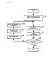
- the operation part 117 first sets a recording condition according to a result of power calibration, then sets a recording condition in the recording waveform generation part 13 based on a result of step S13 described later (step S3).
- the recording waveform generation part 13 generates a recording waveform according to write data, and performs data recording into the optical disk 15 via the optical unit 1 (step S5) .
- This processing is completely not different from processing in a usual case.
- a predetermined amount of data are recorded, then predetermined time is passed, or recording velocity is changed, and then the control part 11 determines whether data recording is finished or not (step S7).
- step S7: Yes route When data recording is finished (step S7: Yes route), processing is finished.
- step S7: No route the control part 11 temporarily stops data recording (step S9). Then, the control part 11 performs reproduction (detection) of a portion into which data recording was performed after stopping data recording last time (step S11).
- step S11 the same operation as in the step S1 is performed as described before.
- the detection instruction part 113 detects the detection pattern of "3T space, 4T mark, and 3T space" based on the code data from the code identification part 111
- the part 113 outputs detection instruction to the detection part 115.
- the detection part 115 performs detection of an amplitude level to an RF signal from the code identification part 111 in response to the detection instruction, and outputs the amplitude level to the operation part 117.
- the operation part 117 specifies the three points centered at the peak as the operation sample, the points being enclosed by the dotted line A in Fig. 8 , and calculates an evaluation value ProfileGap by the expression (1).
- the value of R(x) the value of the ideal signal a as shown in Fig. 8 may be used as itself, or profile data at optimal recording power may be used, which were acquired in power calibration of the step S1 or the like.
- Such processing is carried out every time when the detection pattern is detected, and an average value of the evaluation values ProfileGap is calculated, and stored in the memory of the operation part 117 while being related to a recording power value in each time. Then, the operation part 117 performs recurrence calculation to a set of the average value of the evaluation values ProfileGap stored in the memory, and recording power, and recalculates a proportion coefficient of a line showing a relationship between the evaluation value ProfileGap (specifically an average value) and the recording power.
- the operation part 117 calculates amount of correction (including increase or decrease of the amount) of recording power using difference between an evaluation value ProfileGap calculated last time and an evaluation value ProfileGap at the optimal recording power, and the calculated, proportion coefficient of the line showing the relationship between the evaluation value ProfileGap (specifically the average value) and the recording power (step S13), and then processing is returned to the step S3, and the operation part 117 sets a recording condition in the recording waveform generation part 13.
- the amount of correction is calculated using a product of the difference between the evaluation value ProfileGap calculated last time and the evaluation value ProfileGap at the optimal recording power, and the proportion coefficient.
- amplitude levels of a 4T code are assumed to be I4H and I4L
- amplitude levels of a code having a code length nT are assumed to be InH and InL, the amplitude levels being corresponding or equivalent to peak values respectively.
- the 4T asymmetry is used in place of the evaluation index ProfileGap in the first embodiment.
- the processing flow itself is not different from that in the first embodiment. It is noted that while asymmetry of the shortest symbol and longest symbol, and asymmetry of the shortest symbol and second-shortest symbol are usually used, the 4T asymmetry has not been noticed so far as asymmetry having a code length nearest to effective diameter of a spot, and it is novel as itself to conceive the approximately proportional relationship of the 4T asymmetry as a reference to recording power.
- Fig. 11 shows an example of a relationship between recording power, 4T asymmetry, and nT asymmetry.
- a horizontal axis shows recording power
- a vertical axis shows a value of asymmetry.
- the value of 4T asymmetry is reduced. This is because when the recording power is increased, a 4T mark is disrupted in heat balance with respect to a mark of a long symbol of which the amplitude level reaches the peak.
- a numerical aperture of 4T, I4/In, as an evaluation index according to the embodiment is calculated as follows.
- I ⁇ 4 / In I ⁇ 4 ⁇ H - I ⁇ 4 ⁇ L / InH - InL
- the numerical aperture of 4T, 14/In is used in place of the evaluation index ProfileGap in the first embodiment.
- the processing flow itself is not different from that in the first embodiment.
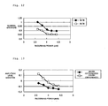
- Fig. 12 shows an example of a relationship between recording power and the numerical aperture of 4T.
- a horizontal axis shows recording power
- a vertical axis shows a numerical aperture.
- An amplitude level variation (I4H/InH) of an evaluation index 4T is calculated by the following expression (4) or (5).
- I ⁇ 4 ⁇ H / InH difference I ⁇ 4 ⁇ H - InH / InH
- I ⁇ 4 ⁇ H / InH ratio I ⁇ 4 ⁇ H / InH
- the amplitude level variation (I4H/InH) of 4T is used in place of the evaluation index ProfileGap in the first embodiment.
- the processing flow itself is not different from that in the first embodiment.
- Fig. 13 shows an example of a relationship between recording power and the amplitude level variation of 4T (difference).
- a horizontal axis shows recording power
- a vertical axis shows amplitude level variation.
- Fig. 14 shows an example of a relationship between recording power and the amplitude level variation of 4T (ratio).
- a horizontal axis shows recording power
- a vertical axis shows amplitude level variation.
- amplitude level variation of the mark 4T is reduced with respect to a mark of a long symbol of which the amplitude level reaches the peak.
- Still another evaluation index can be introduced.
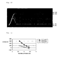
- "3T space, 4T mark, and 3T space” is detected as a detection pattern, and as shown in Fig. 15 , a slice level is given in an area where an amplitude level is different between an ideal signal and a detection signal, and time (detection length) t between intersections of a detection signal of the relevant detection pattern and a shown slice level is assumed to be D(x), and time (ideal length) t' between intersections of an ideal signal and the same slice level as the above is assumed to be R(x).
- D(x) time (ideal length) t' between intersections of an ideal signal and the same slice level as the above
- R(x) time (ideal length) t' between intersections of an ideal signal and the same slice level as the above
- a relationship between the recording power and the evaluation index may be previously acquired in the power calibration, and may be used for calculation of the amount of correction, or similar data may be previously kept in a memory.
Landscapes
- Physics & Mathematics (AREA)
- Optics & Photonics (AREA)
- Optical Recording Or Reproduction (AREA)
- Optical Head (AREA)
Applications Claiming Priority (1)
| Application Number | Priority Date | Filing Date | Title |
|---|---|---|---|
| JP2006309878 | 2006-11-16 |
Publications (2)
| Publication Number | Publication Date |
|---|---|
| EP1923869A2 true EP1923869A2 (de) | 2008-05-21 |
| EP1923869A3 EP1923869A3 (de) | 2008-07-02 |
Family
ID=39030808
Family Applications (1)
| Application Number | Title | Priority Date | Filing Date |
|---|---|---|---|
| EP07254408A Withdrawn EP1923869A3 (de) | 2006-11-16 | 2007-11-08 | Aufzeichnungsleistungskorrekturverfahren sowie Aufzeichnungs- und Wiedergabevorrichtung für einen optischen Datenträger |
Country Status (6)
| Country | Link |
|---|---|
| US (1) | US7881170B2 (de) |
| EP (1) | EP1923869A3 (de) |
| JP (1) | JP4691539B2 (de) |
| KR (1) | KR101000477B1 (de) |
| CN (1) | CN101183540B (de) |
| TW (1) | TW200839748A (de) |
Families Citing this family (4)
| Publication number | Priority date | Publication date | Assignee | Title |
|---|---|---|---|---|
| US7948409B2 (en) * | 2006-06-05 | 2011-05-24 | Mediatek Inc. | Automatic power control system for optical disc drive and method thereof |
| JP4691539B2 (ja) * | 2006-11-16 | 2011-06-01 | 太陽誘電株式会社 | 記録パワー補正方法及び光ディスク記録再生装置 |
| CN102394074B (zh) * | 2008-11-19 | 2015-01-28 | 联发科技股份有限公司 | 光碟机的计算起始驱动信号的方法以及自动功率控制系统 |
| JP2011118961A (ja) * | 2009-12-01 | 2011-06-16 | Taiyo Yuden Co Ltd | データ記録評価方法,装置及びプログラム、並びに光情報記録媒体 |
Citations (1)
| Publication number | Priority date | Publication date | Assignee | Title |
|---|---|---|---|---|
| JP2004234812A (ja) | 2002-12-04 | 2004-08-19 | Ricoh Co Ltd | 光学的情報記録方法、光学的情報記録装置、光学的情報処理装置及び光ディスク装置 |
Family Cites Families (20)
| Publication number | Priority date | Publication date | Assignee | Title |
|---|---|---|---|---|
| JP3858613B2 (ja) * | 2001-03-23 | 2006-12-20 | ティアック株式会社 | 光ディスク装置 |
| US6636468B2 (en) * | 2001-03-26 | 2003-10-21 | Oak Technology, Inc. | Method and apparatus for laser power control during recording |
| JP4351813B2 (ja) * | 2001-04-20 | 2009-10-28 | 株式会社東芝 | 光ディスク装置 |
| JP3858731B2 (ja) * | 2002-03-07 | 2006-12-20 | 日本電気株式会社 | 記録状態検出指数の算出方法並びにこれを用いた光ディスク記録方法及び光ディスク記録装置 |
| JP2003331426A (ja) * | 2002-05-09 | 2003-11-21 | Mitsumi Electric Co Ltd | 光ディスク装置 |
| WO2004029944A1 (ja) * | 2002-09-30 | 2004-04-08 | Nec Corporation | 記録条件設定方法及びそれを用いた情報記録装置 |
| KR20040037894A (ko) * | 2002-10-30 | 2004-05-08 | 삼성전자주식회사 | 광 기록 매체의 자동 기록 최적화 방법 및 이를 수행하는광 기록/재생 장치 |
| JP2005310351A (ja) * | 2004-03-25 | 2005-11-04 | Sanyo Electric Co Ltd | 光ディスク装置 |
| WO2005109418A1 (en) * | 2004-05-12 | 2005-11-17 | Koninklijke Philips Electronics N.V. | Optimal power control |
| JP4280996B2 (ja) * | 2004-05-13 | 2009-06-17 | 太陽誘電株式会社 | 光情報記録装置 |
| JP4154608B2 (ja) * | 2004-05-27 | 2008-09-24 | 日本電気株式会社 | 情報記録媒体への記録方法及び情報記録再生装置並びに情報記録媒体 |
| WO2006001423A1 (ja) | 2004-06-28 | 2006-01-05 | Pioneer Corporation | 情報記録装置、情報記録方法及び情報記録プログラム |
| JP4353023B2 (ja) * | 2004-07-30 | 2009-10-28 | 株式会社日立製作所 | 試し書き方法、情報記録方法 |
| JP3998011B2 (ja) * | 2004-09-08 | 2007-10-24 | 株式会社日立製作所 | 光ディスク装置 |
| TWI259447B (en) * | 2005-01-11 | 2006-08-01 | Lite On It Corp | Optical reproducing/recording apparatus and method for detecting RF signal quality executed thereby |
| JP4244039B2 (ja) * | 2005-02-24 | 2009-03-25 | 太陽誘電株式会社 | 光情報記録装置および方法および信号処理回路並びに光情報再生装置および方法および信号処理回路 |
| JP4395455B2 (ja) * | 2005-02-24 | 2010-01-06 | 太陽誘電株式会社 | 光情報記録装置および方法および信号処理回路 |
| JP4818126B2 (ja) * | 2005-04-28 | 2011-11-16 | 三菱電機株式会社 | 光記録方法、光記録装置、及び光記録再生装置 |
| JP4440207B2 (ja) * | 2005-12-14 | 2010-03-24 | 太陽誘電株式会社 | 光情報記録再生装置、光情報記録処理方法、光情報記録媒体、プログラム、及び中央演算装置 |
| JP4691539B2 (ja) * | 2006-11-16 | 2011-06-01 | 太陽誘電株式会社 | 記録パワー補正方法及び光ディスク記録再生装置 |
-
2007
- 2007-10-30 JP JP2007281129A patent/JP4691539B2/ja not_active Expired - Fee Related
- 2007-11-07 US US11/936,700 patent/US7881170B2/en not_active Expired - Fee Related
- 2007-11-08 EP EP07254408A patent/EP1923869A3/de not_active Withdrawn
- 2007-11-09 KR KR1020070114514A patent/KR101000477B1/ko not_active Expired - Fee Related
- 2007-11-14 CN CN2007101871090A patent/CN101183540B/zh not_active Expired - Fee Related
- 2007-11-14 TW TW096143088A patent/TW200839748A/zh not_active IP Right Cessation
Patent Citations (1)
| Publication number | Priority date | Publication date | Assignee | Title |
|---|---|---|---|---|
| JP2004234812A (ja) | 2002-12-04 | 2004-08-19 | Ricoh Co Ltd | 光学的情報記録方法、光学的情報記録装置、光学的情報処理装置及び光ディスク装置 |
Also Published As
| Publication number | Publication date |
|---|---|
| JP4691539B2 (ja) | 2011-06-01 |
| KR20080044767A (ko) | 2008-05-21 |
| TW200839748A (en) | 2008-10-01 |
| CN101183540B (zh) | 2010-08-25 |
| JP2008146811A (ja) | 2008-06-26 |
| TWI373763B (de) | 2012-10-01 |
| CN101183540A (zh) | 2008-05-21 |
| KR101000477B1 (ko) | 2010-12-14 |
| US20080151714A1 (en) | 2008-06-26 |
| US7881170B2 (en) | 2011-02-01 |
| EP1923869A3 (de) | 2008-07-02 |
Similar Documents
| Publication | Publication Date | Title |
|---|---|---|
| JP5450376B2 (ja) | 信号評価方法および信号評価装置 | |
| EP2043102A1 (de) | Bewertungsverfahren für ein informationsaufzeichnungsmedium, informationsaufzeichnungsmedium, verfahren zur herstellung eines informationsaufzeichnungsmediums, signalverarbeitungsverfahren und zugangssteuerungsvorrichtung | |
| KR100951629B1 (ko) | 데이터 기록 평가 방법 및 광 디스크 기록 재생 장치 | |
| EP2343702A1 (de) | Informationsaufzeichnungsmedium und aufzeichnungs-/wiedergabevorrichtung | |
| JP4900391B2 (ja) | 光学的情報記録再生装置及び記録マーク品質測定方法 | |
| US7881170B2 (en) | Recording power correction method and recording and reproduction apparatus for optical disk | |
| JPWO2006112277A1 (ja) | 光学的情報記録媒体へのデータ記録における記録パルス条件の最適化方法 | |
| JP4395455B2 (ja) | 光情報記録装置および方法および信号処理回路 | |
| JP2007207357A (ja) | 光学的情報再生方法及び装置 | |
| EP1956595B1 (de) | Verfahren zur Anpassung der Aufzeichnungsbedingungen für optische Plattenaufzeichnungs-/-wiedergabesysteme, optische Aufzeichnungswiedergabevorrichtung und optische Platte | |
| JP4395450B2 (ja) | 光情報記録装置および信号処理回路 | |
| JP2009238301A5 (de) | ||
| JP2009238301A (ja) | データ記録評価方法及び光ディスク記録再生装置 | |
| KR20070097512A (ko) | 저장 매체 상의 광학 이펙트의 분석 | |
| HK1115934A (en) | Recording power correction method and recording and reproduction apparatus for optical disk | |
| HK1121283B (en) | Recording condition adjusting method of optical disc recording/playing system, optical recording playing device and optical disc | |
| JP2009140566A (ja) | 記録ストラテジ調整方法、および情報記録再生装置 | |
| KR20090091827A (ko) | 기록 스트래티지 조정 방법 및 광 디스크 기록/재생 장치 |
Legal Events
| Date | Code | Title | Description |
|---|---|---|---|
| PUAI | Public reference made under article 153(3) epc to a published international application that has entered the european phase |
Free format text: ORIGINAL CODE: 0009012 |
|
| AK | Designated contracting states |
Kind code of ref document: A2 Designated state(s): AT BE BG CH CY CZ DE DK EE ES FI FR GB GR HU IE IS IT LI LT LU LV MC MT NL PL PT RO SE SI SK TR |
|
| AX | Request for extension of the european patent |
Extension state: AL BA HR MK RS |
|
| PUAL | Search report despatched |
Free format text: ORIGINAL CODE: 0009013 |
|
| AK | Designated contracting states |
Kind code of ref document: A3 Designated state(s): AT BE BG CH CY CZ DE DK EE ES FI FR GB GR HU IE IS IT LI LT LU LV MC MT NL PL PT RO SE SI SK TR |
|
| AX | Request for extension of the european patent |
Extension state: AL BA HR MK RS |
|
| AKX | Designation fees paid | ||
| 17P | Request for examination filed |
Effective date: 20090213 |
|
| RBV | Designated contracting states (corrected) |
Designated state(s): AT BE BG CH CY CZ DE DK EE ES FI FR GB GR HU IE IS IT LI LT LU LV MC MT NL PL PT RO SE SI SK TR |
|
| REG | Reference to a national code |
Ref country code: DE Ref legal event code: 8566 |
|
| 17Q | First examination report despatched |
Effective date: 20090330 |
|
| STAA | Information on the status of an ep patent application or granted ep patent |
Free format text: STATUS: THE APPLICATION IS DEEMED TO BE WITHDRAWN |
|
| 18D | Application deemed to be withdrawn |
Effective date: 20121211 |