EP1923818A1 - Barcodelesegerät - Google Patents
Barcodelesegerät Download PDFInfo
- Publication number
- EP1923818A1 EP1923818A1 EP07020083A EP07020083A EP1923818A1 EP 1923818 A1 EP1923818 A1 EP 1923818A1 EP 07020083 A EP07020083 A EP 07020083A EP 07020083 A EP07020083 A EP 07020083A EP 1923818 A1 EP1923818 A1 EP 1923818A1
- Authority
- EP
- European Patent Office
- Prior art keywords
- reader according
- barcode reader
- optical
- heat
- heating element
- Prior art date
- Legal status (The legal status is an assumption and is not a legal conclusion. Google has not performed a legal analysis and makes no representation as to the accuracy of the status listed.)
- Granted
Links
Images

Classifications
-
- G—PHYSICS
- G06—COMPUTING OR CALCULATING; COUNTING
- G06K—GRAPHICAL DATA READING; PRESENTATION OF DATA; RECORD CARRIERS; HANDLING RECORD CARRIERS
- G06K7/00—Methods or arrangements for sensing record carriers, e.g. for reading patterns
- G06K7/10—Methods or arrangements for sensing record carriers, e.g. for reading patterns by electromagnetic radiation, e.g. optical sensing; by corpuscular radiation
- G06K7/10544—Methods or arrangements for sensing record carriers, e.g. for reading patterns by electromagnetic radiation, e.g. optical sensing; by corpuscular radiation by scanning of the records by radiation in the optical part of the electromagnetic spectrum
Definitions
- the invention relates to a bar code reader with a housing in which optical and electronic components and an electrical heating element are arranged with a heat conducting body, wherein the heating element is thermally conductively connected to the heat conducting body.
- Barcode readers of this kind for reading barcodes are used, for example, as mobile handheld devices or stationary devices on conveyor systems in the commercial and industrial sector.
- the read barcodes are used to identify the labeling of various intermediate or end products, such as workpieces, construction and machine elements, consumer goods, medicines and foodstuffs.
- the use of the bar code readers also makes it necessary, even at low ambient temperatures, in unheated warehouses, in outdoor storage areas or in cold stores. In such applications, ambient temperatures can be much lower than 0 ° C, in cold stores typically to about - 40 ° C.
- the thermally sensitive optical components of the bar code reader include components with superficially optical components, such as a transmitting light emitting transmitter with, for example, a laser diode, a receive light receiving receiver with photodiode o. The like. And deflecting mirrors and deflection units with driven movable mirrors for periodic deflection of the transmitter and receiving light beams.
- a deflection unit has, for example, a rotating polygon mirror wheel or a pivoting mirror on a noise-sensitive electronic component of the bar code reader, for example, forms the predominantly electronic components for control and regulation comprehensive integrated circuit board.
- generic bar code readers have an electrical heating element integrated in the housing in order to keep the internal temperature within the housing within a permissible operating temperature range.
- the integrated heating element can be formed, for example, by a resistance element or a semiconductor element.
- the beam passage window has a disk heater, e.g. in the form of heating wires, which are applied to the disc to avoid fogging of the beam passage window.
- the integrated heating element is connected to a heat conducting body in order to distribute the heat generated by the heating element in the housing interior.
- a bar code reader which has a heating element which rests on a heat-conducting body and is in thermal contact therewith.
- the thermally conductive body is mounted on a heat-insulating support of the housing and preferably formed by a plate made of aluminum.
- the heat-insulating support ensures that the plate is kept at a distance from the housing.
- the plate extends over wide areas of the housing interior at a distance from the optical and electronic components.
- the heat generated by the heating element is transmitted by heat conduction directly to the heat-conducting body in plate shape, which in turn emits the heat preferably by heat radiation to the interior of the housing and thus to the optical and electronic components.
- the heat-insulating support of the heat-conducting body prevents heat transfer by heat conduction to the housing, bringing almost the entire heating power of the heating element is effectively used to heat the optical and electronic components inside the housing.
- the arrangement of the plate above the polygon mirror wheel which generates an air circulation inside the housing as a result of the rotation.
- the heat is not distributed sufficiently evenly in the interior of the housing, so that set at extremely low ambient temperatures locally significantly different indoor temperatures.
- a temperature sensor integrated in the housing interior detects an actual temperature that corresponds to the setpoint temperature in the permissible operating temperature range and consequently causes the switching off of the heating element or the operational readiness of the barcode reader is signaled, although in certain areas of the housing interior, the permissible operating temperature has not been reached .
- the temperature sensor is placed at such a thermally disadvantaged area of the housing interior, a considerably higher heating power of the heating element is required to achieve the permissible operating temperature at this location, which also leads to an unnecessary over-temperature of the thermally favorably located optical and electronic components. This not only increases the energy consumption, but leads to thermal overload, in particular of the electronic components, and to premature wear of the heating element.
- the space requirement of extending over wide areas of the housing interior plate is a constructive limitation for the bar code reader.
- the invention is therefore based on the object to improve the heat distribution in a generic bar code reader with low energy and design effort.
- the heat-conducting body is formed by a receiving console for holding the optical and / or electronic components.
- the heat can reach the optical and electronic components in an energetically favorable way by thermal conduction via the thermally conductive receiving console and heat-conducting connecting elements.
- the heat transfer to the optical and electronic components is thus less due to the energetically more complex heat radiation according to previous versions in the prior art as by heat conduction within the heat-conducting materials of recording console and fasteners.
- the receiving console is thermally insulated connected to the housing.
- the receiving console is thermally insulated connected to the housing.
- the receiving console has at least one web which protrudes into the housing interior space between the optical and electronic components. These webs support as heat-transferring surfaces, the heat conduction by additional convective heat transfer from the surfaces of the receiving console to the air space of the housing interior.
- the air flow generated in the interior of the housing with the movement of the mirror can on the one hand increase the heat-transferring convection action on the webs and, in addition, the distribute the heat well inside the enclosure.
- the convection effect can be increased if the web is designed such that it at least partially surrounds the polygon mirror wheel.
- the air ventilation reaches large surface portions of the web, without the web hinders the optical function of the movable mirror.
- the receiving console has at least one holding element, to which the heating element can be attached, screwed or latched.
- a convenient replacement of the heating element allows for example for maintenance or wear.
- the placement of the heating element can be varied locally as required. If, for example, the heat losses of the individual optical and electronic components generated are approximately the same, a central arrangement of the heating element at a central center position of the receiving console for effective heat distribution of the heat generated by the heating element is low, since the heat is distributed equally in all directions.
- the excess temperature of the heat-conducting receiving console is greatest compared to the air space of the housing interior, there also reaches the convective heat transfer of the recording console, in particular the webs, their optimum.
- Konvezzysrial when the heating element in a vicinity of the movably driven mirror, preferably at a nearby web, is arranged.
- a plurality of heating elements are provided, which are modularly switchable by means of a central control unit.
- This not only allows a favorable distributed arrangement of the heat sources but also allows selective switching on or off of heating elements, depending on the needs and conditions of use of the bar code reader.
- a targeted and more uniform heat distribution can be achieved by means of this modular design of the heating elements. Due to the decentralized distribution of the heat output, a local thermal overload of the optical and electronic components is also avoided.
- a disk heating element for heating a jet passage disk, it is advantageous if this disk heating element can be switched to the heating elements in a modular manner by means of the central control unit.
- the central control unit allows the disk heater to operate separately from the heating elements.
- the low heat output of the Scheibencreamides the remaining heating elements need not be switched on. This is used for such, not rarely occurring applications, less heating energy and at the same time reduces the wear of the heating elements. In addition, an unnecessary thermal overload of the optical and electronic components avoided.
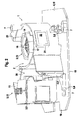
- the bar code reader 1 is shown without its housing in Fig. 1 and 2, whereby a view of the interior 2 of the housing with the internal structure of the bar code reader 1 is made possible.
- the internal structure of the bar code reader comprises optical and electronic components 3, 4, which are held together by a receiving console 5.
- the receiving console 5 serves as a support frame for the fixed arrangement of the optical and electronic components 3, 4 in the interior 2 of the housing and the other as a heat-conducting body 6.
- the frame-like receiving console 5 is made of stable and thermally conductive material, such as zinc, and extends At its outer ends, the receiving console 5 mounting holes 7, by means of which the receiving console 5 is connected to a housing bottom and lid, not shown, thermally insulating in an expansive, membered form substantially over the entire extent of the housing interior 2 of the barcode reader.
- optical components 3 in the context of this invention are those equipped with substantially optical components functional units of Barcode reader 1 referred to.
- the optical components 3 in the present embodiment of the bar code reader 1 according to the invention are a transmitter emitting light emitting transmitter 9 with preferably a laser diode, a receive light receiving receiver 8 with, for example, a photodiode, a deflecting and concave mirrors 10, 11 existing mirror and a deflection unit 13 with a Polygonaptrad 14.
- Electronic components, such as the evaluation unit for processing the receiver light beams and recognition of the barcode are mainly combined on the central circuit board 15, which forms a significant electronic component 4 of the barcode reader 1 because of their predominantly equipped with electronic components.
- the transmission beams, emitted by the transmitter 9, are deflected by the deflection mirror 10 and guided by the deflection unit 13.
- the polygon mirror wheel 14 of the deflection unit 13, driven by a motor, not shown, rotates at a certain speed about a rotation axis 16.
- the polygon shaped peripheral surface of the polygon mirror wheel 14 generates a periodic deflection of the transmitted light beam in a certain reflection angle range.
- the transmitted light rays then penetrate a beam passage window in the housing, not shown, and reach the bar code to be recognized in a detection range corresponding to the reflection angle range.
- the equipment of the bar code reader 1 with an additional module with additional optical component the transmitted light beams are passed before exiting the beam passage window via a deflection unit with pivoting mirror.
- the transmitted light beams are periodically deflected in a reflection angle range superposed by a second dimension.
- the receiver light beams reflected by the bar code essentially run in the opposite direction through the beam passage window, are optionally deflected by the pivoting mirror and then by the polygonal mirror wheel 14 and directed onto the concave mirror 11, which transmits the receiver light beam focused feeds the receiver 8.
- the receiver light beams amplitude-modulated by the bar patterns of the bar codes are converted into electrical signals, decoded and evaluated.
- the above-described optical components 3 and the circuit board 15 are thermally conductively connected to the receiving console 5.
- the printed circuit board 15 is partially flush mounted on a flat underside 18 of the receiving console 5 and is thus in thermal contact with the receiving console 5.
- Receiver 8, deflecting mirror 10 and deflection unit 13 are connected directly to the receiving console 5.
- the heat can be transferred very well by heat conduction to the optical and electronic components 3, 4.
- the unit comprising receiving console 5, optical components 3 and printed circuit board 15 is thermally insulated from the surrounding housing in order to prevent heat loss to the environment by heat conduction to the housing.
- pads or spacers made of heat-insulating material between the receiving console 5 and the housing parts, in particular in the region of the mounting holes 7, are provided.
- the receiving console 5 extends not only flat in the housing interior 2 of the barcode reader 1 but has on its upper side 19 over cantilevered webs 20 which protrude between the optical components 3 in the housing interior 2. They promote the convective heat transfer to the air of the housing interior 2 in addition to the heat conduction along the receiving console 5.
- the running in close proximity to the Polygonaptrad 14 web 20 encloses the Polygonaptrad 14 circular and almost complete, so that here the convective heat transfer through the polygon mirror 14th generated air flow is supported.
- FIG. 2 there is a holding element 21 to which a heating element 22 is detachably mounted.
- the heating element 22 is in heat-conducting contact with the Recording console 5.
- the electric heating element 22 serves as a heat source for heating the optical and electronic components 3, 4 of the bar code reader 1 by means of the receiving console 5 in the manner described above.
- the present embodiment shows only a holding element 21 for the arrangement of a heating element 22, wherein the invention is not limited thereto and the arrangement of a plurality of heating elements 22 by means of further holding elements 21 at different points of the receiving console 5 is readily conceivable.
- the electrical heating element 22 contains, for example, a PTC resistance element or a semiconductor element and, if appropriate, can be modularly connected and regulated in addition to other heating elements 22 by means of a microcontroller as a control and regulation unit.
- the actual value of the temperature in the housing interior 2 is detected by a temperature sensor located therein and compared with a desired value. According to the control deviation, the heating power of the heating element 22 or the heating elements 22 is activated.
- the receiving console 5 as a support frame and heat-conducting body 6, the heat is transported from the heat source constructive and energetically favorable to the optical and electronic components 3, 4 and distributed as it were throughout the housing interior 2.
- the particular embodiments of the receiving console 5 in cooperation with the heating element 22 improves the energetically favorable heat distribution in the manner described above.
Landscapes
- Physics & Mathematics (AREA)
- Engineering & Computer Science (AREA)
- Electromagnetism (AREA)
- Artificial Intelligence (AREA)
- Toxicology (AREA)
- General Health & Medical Sciences (AREA)
- Health & Medical Sciences (AREA)
- Computer Vision & Pattern Recognition (AREA)
- General Physics & Mathematics (AREA)
- Theoretical Computer Science (AREA)
- Cooling Or The Like Of Electrical Apparatus (AREA)
- Mechanical Optical Scanning Systems (AREA)
- Electrochromic Elements, Electrophoresis, Or Variable Reflection Or Absorption Elements (AREA)
- Polishing Bodies And Polishing Tools (AREA)
Abstract
Description
- Die Erfindung betrifft ein Barcodelesegerät mit einem Gehäuse, in welchem optische und elektronische Komponenten sowie ein elektrisches Heizelement mit einem Wärmeleitkörper angeordnet sind, wobei das Heizelement wärmeleitend mit dem Wärmeleitkörper verbunden ist.
- Derartige Barcodelesegeräte zum Lesen von Barcodes werden beispielsweise als mobile Handgeräte oder stationäre Geräte an Förderanlagen im gewerblichen und industriellen Bereich eingesetzt. Die gelesenen Barcodes dienen zur Identifikation der Etikettierung verschiedenster Zwischen- oder Endprodukte, wie zum Beispiel Werkstücke, Bau- und Maschinenelemente, Gebrauchsgüter, Medikamente und Lebensmittel. Je nach dem Lagerort der zu identifizierenden Produkte macht sich der Einsatz der Barcodelesegeräte auch bei niedrigen Umgebungstemperaturen in unbeheizten Lagerhallen, auf Lagerplätzen im Außenbereich oder in Kühlhäusern erforderlich. Bei derartigen Anwendungsfällen können Umgebungstemperaturen herrschen, die weit unter 0°C liegen, in Kühlhäusern typischer Weise bis ca. - 40°C. Diese Anwendungsbedingungen führen zu Betriebsstörungen des Barcodelesegerätes, z.B. infolge des Beschlagens des Strahldurchtrittsfensters, der Linsen und Spiegel der optischen Komponenten und infolge des Funktionsausfalls der elektronischen Bauteile. Zu den thermisch empfindlichen, optischen Komponenten des Barcodelesegerätes zählen Komponenten mit vordergründig optischen Bauelementen, wie ein Sendelichtstrahlen emittierenden Sender mit beispielsweise einer Laserdiode, ein Empfangslichtstrahlen empfangenden Empfänger mit Photodiode o. dgl. sowie Umlenkspiegel und Ablenkeinheiten mit angetriebenen beweglichen Spiegeln zur periodischen Ablenkung der Sende- und Empfangslichtstrahlen. Eine solche Ablenkeinheit weist beispielsweise ein rotierendes Polygonspiegelrad oder einen Schwenkspiegel auf Eine störempfindliche elektronische Komponente des Barcodelesegerätes bildet beispielsweise die vornehmlich elektronische Bauteile zur Steuerung und Regelung umfassende integrierte Leiterplatte.
- Um die Funktionsfähigkeit dieser optischen und elektronischen Komponenten des Barcodelesegerätes auch unter den kritischen Anwendungsbedingungen aufrecht zu erhalten, verfügen gattungsgemäße Barcodelesegeräte über ein im Gehäuse integriertes elektrisches Heizelement, um die Innentemperatur innerhalb des Gehäuse in einem zulässigen Betriebstemperaturbereich zu halten. Das integrierte Heizelement kann beispielsweise von einem Widerstandselement oder einem Halbleiterelement gebildet sein. Ergänzend verfügt das Strahldurchtrittsfenster über ein Scheibenheizelement, z.B. in Form von Heizdrähten, welche auf die Scheibe aufgebracht sind, um das Beschlagen des Strahldurchtrittsfensters zu vermeiden.
- Gattungsgemäß ist das integrierte Heizelement mit einem Wärmeleitkörper verbunden, um die vom Heizelement erzeugte Wärme im Gehäuseinnenraum zu verteilen. Aus der Druckschrift
DE 199 33 518 B4 ist ein Barcodelesegerät bekannt, der über ein Heizelement verfügt, welches auf einem wärmeleitenden Körper aufsitzt und in Wärmekontakt mit diesem steht. Der wärmeleitende Körper ist auf einer wärmeisolierenden Auflage des Gehäuses gelagert und vorzugsweise von einer Platte aus Aluminium gebildet. Die wärmeisolierende Auflage gewährleistet, dass die Platte in einem Abstand zum Gehäuse gehalten wird. Vorteilhaft erstreckt sich die Platte über weite Bereiche des Gehäuseinnenraumes in einem Abstand zu den optischen und elektronischen Komponenten. Die vom Heizelement erzeugte Wärme wird durch Wärmeleitung direkt auf den wärmeleitenden Körper in Plattengestalt übertragen, der wiederum die Wärme vorzugsweise durch Wärmestrahlung an das Innere des Gehäuses und damit an die optischen und elektronischen Komponenten abgibt. Die wärmeisolierende Auflage des Wärmeleitkörpers verhindert dabei einen Wärmeübergang durch Wärmeleitung an das Gehäuse, womit nahezu die gesamte Heizleistung des Heizelementes effektiv dazu verwendet wird, um die optischen und elektronischen Komponenten im Inneren des Gehäuses aufzuheizen. Für eine zusätzliche Wärmeverteilung sorgt die Anordnung der Platte oberhalb des Polygonspiegelrades, das infolge der Rotation eine Luftzirkulation im Gehäuseinneren erzeugt. - Trotz dieser Maßnahmen zur Wärmeverteilung wird die Wärme nicht genügend gleichmäßig im Innenraum des Gehäuses verteilt, so dass sich bei extrem niedrigen Umgebungstemperaturen örtlich erheblich unterschiedliche Innenraumtemperaturen einstellen.
- So kann es sein, dass beispielsweise ein im Gehäuseinnenraum integrierter Temperatursensor eine Isttemperatur erfasst, die der Solltemperatur im zulässigen Betriebstemperaturbereich entspricht und infolgedessen das Abschalten des Heizelementes veranlasst oder die Betriebsbereitschaft des Barcodelesegerätes signalisiert wird, obwohl in bestimmten Bereichen des Gehäuseinnenraumes die zulässige Betriebstemperatur nicht erreicht wurde. Ist andererseits der Temperatursensor an einem solchen thermisch benachteiligten Bereich des Gehäuseinnenraumes platziert, wird zur Erreichung der zulässigen Betriebstemperatur an diesem Ort eine erheblich höhere Heizleistung des Heizelementes erforderlich, die zudem zu einer unnötigen Übertemperierung der thermisch günstiger gelegenen optischen und elektronischen Komponenten führt. Das erhöht nicht nur den Energieverbrauch, sondern führt zur thermischen Überlastung, insbesondere der elektronischen Bauteile, und zum vorzeitigen Verschleiß des Heizelementes. Außerdem stellt der Platzbedarf der sich über weite Bereiche des Gehäuseinnenraumes erstreckenden Platte eine konstruktive Einschränkung für das Barcodelesegerät dar.
- Der Erfindung liegt daher die Aufgabe zugrunde, die Wärmeverteilung in einem gattungsgemäßen Barcodelesegerät mit geringem energetischem und konstruktivem Aufwand zu verbessern.
- Die Aufgabe wird erfindungsgemäß mit den Merkmalen des Patentanspruches 1 gelöst. Die in den Unteransprüchen 2 bis 17 aufgeführten Maßnahmen beschreiben vorteilhafte Ausgestaltungen des erfindungsgemäßen Barcodelesegerätes.
- Bei dem erfindungsgemäßen Barcodelesegeräte ist der Wärmeleitkörper von einer Aufnahmekonsole zur Halterung der optischen und/oder elektronischen Komponenten gebildet.
- Damit erübrigen sich die konstruktiven Aufwendungen für die Installation eines gesonderten Wärmeleitkörpers im Innenraum des Gehäuses. Die ohnehin notwendige Tragekonstruktion für die Halterung der optischen und/oder elektronischen Komponenten im Gehäuse übernimmt in Form einer Aufnahmekonsole zugleich die Funktion des Wärmeleitkörpers. Aus dem statischem Erfordernis einer zentralen Halterung für die optischen und/oder elektronischen Komponenten ergibt sich, dass die Aufnahmekonsole verzweigt oder flächig übergreifend den gesamten Innenraum des Gehäuses überspannt. In gleichzeitiger Funktion als Wärmeleitkörper - wobei die Aufnahmekonsole vorzugsweise aus gut wärmeleitenden Metall, insbesondere Zink oder Aluminium bestehtwird die Wärme sehr effektiv im Innenraum des Gehäuses verteilt.
- Sind die optischen und/oder elektronischen Komponenten zudem wärmeleitend mit der Aufnahmekonsole verbunden, kann die Wärme auf energetisch günstigem Wege durch Wärmeleitung über die wärmeleitende Aufnahmekonsole und wärmeleitenden Verbindungselemente zu den optischen und elektronischen Komponenten gelangen. Die Wärmeübertragung auf die optischen und elektronischen Komponenten erfolgt somit weniger durch die energetisch aufwändigere Wärmestrahlung nach bisherigem Ausführungen im Stand der Technik als vielmehr durch Wärmeleitung innerhalb der wärmeleitenden Materialien von Aufnahmekonsole und Verbindungselemente.
- Des Weiteren ist es vorteilhaft, wenn die Aufnahmekonsole wärmeisolierend mit dem Gehäuse verbunden ist. Somit entsteht nahezu kein Wärmeverlust an die Umgebung des Barcodelesegerätes infolge der Wärmeleitung von der Aufnahmekonsole zum Gehäuse.
- In einer günstigen Ausgestaltung weist die Aufnahmekonsole zumindest einen Steg auf, der in den Gehäuseinnenraum zwischen den optischen und elektronischen Komponenten ragt. Diese Stege unterstützen als wärmeübertragende Flächen die Wärmeleitung durch zusätzlichen konvektiven Wärmeübergang von den Oberflächen der Aufnahmekonsole an den Luftraum des Gehäuseinnenraumes.
- Ist einer oder mehrere der Stege in unmittelbarer Nähe zu der optischen Komponente angeordnet, die einen beweglich angetriebenen Spiegel, vorzugsweise ein rotierendes Polygonspiegelrad aufweist, kann die mit der Bewegung des Spiegels erzeugte Luftströmung im Gehäuseinneren zum einen die wärmeübertragende Konvektionswirkung an den Stegen erhöhen und zusätzlich die abgegebene Wärme gut im Innenraum des Gehäuses verteilen. Insbesondere kann die Konvektionswirkung dadurch erhöht werden, wenn der Steg derart gestaltet ist, dass er das Polygonspiegelrad zumindest teilweise umfasst. Somit erreicht die Luftventilation große Flächenabschnitte des Steges, ohne das der Steg die optische Funktion des beweglichen Spiegels behindert.
- Besonders vorteilhaft ist, dass die Aufnahmekonsole mindestens ein Halteelement aufweist, an welches das Heizelement ansteckbar, anschraubbar oder einrastbar ist. Somit ermöglicht sich ein bequemer Austausch des Heizelementes z.B. zu Wartungszwecken oder bei Verschleiß. Sind mehrere Halteelemente vorgesehen, kann die Platzierung des Heizelementes je nach Bedarf örtlich variiert werden. Ist beispielsweise die eigens erzeugte Verlustwärme der einzelnen optischen und elektronischen Komponenten annähernd gleich, ist eine zentrale Anordnung des Heizelementes an einer zentralen Mittenposition der Aufnahmekonsole zur effektiven Wärmeverteilung der durch das Heizelement erzeugten Wärme günstig, da hierdurch die Wärme gleichermaßen in alle Richtungen verteilt wird.
- Da in der nahen Umgebung des Heizelementes die Übertemperatur der wärmeleitenden Aufnahmekonsole gegenüber dem Luftraum des Gehäuseinnenraumes am größten ist, erreicht dort auch die konvektive Wärmeübertragung der Aufnahmekonsole, insbesondere der Stege, ihr Optimum. Somit wirkt es sich verstärkend auf Konvektionswirkung aus, wenn das Heizelement in einem Nahbereich zum beweglich angetriebenen Spiegel, vorzugsweise an einem nahe gelegenen Steg, angeordnet ist.
- In einer besonders vorteilhaften Ausgestaltung sind mehrere, Heizelemente vorgesehen, die mittels einer zentralen Steuer- und Regeleinheit modular schaltbar sind. Das erlaubt nicht nur eine günstige verteilte Anordnung der Wärmequellen sondern ermöglicht auch ein selektives Zu- bzw. Abschalten von Heizelementen, je nach Bedarf und Einsatzbedingungen des Barcodelesegerätes. Insbesondere bei größeren Barcodelesegeräten, z.B. bei Barcodelesegeräten mit Schwenkspiegel, kann mittels dieses modularen Aufbaus der Heizelemente eine gezielte und gleichmäßigere Wärmeverteilung erreicht werden. Durch die dezentrale Verteilung der Wärmeleistung wird zudem eine örtliche thermische Überlastung der optischen und elektronischen Komponenten vermieden.
- Ist ein Scheibenheizelement zur Beheizung einer Strahldurchtrittsscheibe vorgesehen, ist es vorteilhaft, wenn dieses Scheibenheizelement mittels der zentralen Steuer- und Regeleinheit modular zu den Heizelementen schaltbar ist. Bei bestimmten Witterungsbedingungen ist es möglich, dass die Strahldurchtrittsscheibe beschlägt, obwohl die Umgebungstemperatur innerhalb des zulässigen Betriebstemperaturbereiches des Barcodelesegerätes liegt. Die modulare Betriebsweise der zentralen Steuer- und Regeleinheit erlaubt das Scheibenheizelement separat zu den Heizelementen zu betreiben. Als Maßnahme gegen das Beschlagen genügt die geringe Heizleistung des Scheibenheizelementes, die übrigen Heizelemente müssen nicht zugeschaltet werden. Damit wird für derartige, nicht selten auftretende Einsatzfälle, weniger Heizenergie verbraucht und zugleich der Verschleiß der Heizelemente gemindert. Zudem wird eine unnötige thermische Überlastung der optischen und elektronischen Komponenten vermieden.
- Das erfindungsgemäße Barcodelesegerät wird nachfolgend an einem Ausführungsbeispiel näher erläutert. Die zugehörigen Zeichnungen zeigen in einer schematischen Darstellung in
- Figur 1
- eine Draufsicht auf den Innenaufbau des erfindungsgemäßen Barcodelesegerätes nach dem Ausführungsbeispiel und in
- Figur 2
- eine Seitenansicht auf den Innenaufbau des erfindungsgemäßen Barcodelesegerätes nach dem Ausführungsbeispiel.
- Zur besseren Veranschaulichung der Erfindung ist in Fig. 1 und 2 das Barcodelesegerät 1 ohne sein Gehäuse dargestellt, wodurch eine Einsichtnahme auf den Innenraum 2 des Gehäuses mit dem Innenaufbau des Barcodelesegerätes 1 ermöglicht ist. Der Innenaufbau des Barcodelesegerätes umfasst optische und elektronische Komponenten 3, 4, die gemeinsam von einer Aufnahmekonsole 5 gehalten sind. Die Aufnahmekonsole 5 dient zum einen als Tragegestell zur befestigten Anordnung der optischen und elektronischen Komponenten 3, 4 im Innenraum 2 des Gehäuses und zum anderen als Wärmleitkörper 6. Die gestellartige Aufnahmekonsole 5 besteht aus stabilem und wärmeleitenden Material, wie zum Beispiel Zink, und erstreckt sich in ausladender, gliedriger Gestalt im Wesentlichen über die gesamten Ausdehnung des Gehäuseinnenraumes 2 des Barcodelesegerätes 1. An ihre äußeren Enden weist die Aufnahmekonsole 5 Befestigungsbohrungen 7 auf, mittels derer die Aufnahmekonsole 5 mit einem nicht dargestellten Gehäuseboden und -deckel thermisch isolierend verbunden wird.
- Als optische Komponenten 3 im Sinne dieser Erfindung sind solche, mit im Wesentlichen optischen Bauelementen ausgestatteten Funktionseinheiten des Barcodelesegerätes 1 bezeichnet. Die optischen Komponenten 3 im vorliegenden Ausführungsbeispiel des erfindungsgemäßen Barcodelesegerätes 1 sind ein Sendelichtstrahlen emittierender Sender 9 mit vorzugsweise einer Laserdiode, ein Empfangslichtstrahlen empfangender Empfänger 8 mit beispielsweise einer Photodiode, ein aus Umlenk- und Hohlspiegel 10, 11 bestehender Spiegel sowie eine Ablenkeinheit 13 mit einem Polygonspiegelrad 14. Elektronische Bauteile, wie z.B. die Auswerteeinheit zur Verarbeitung der Empfängerlichtstrahlen und Erkennung des Barcodes sind hauptsächlich auf der zentralen Leiterplatte 15 vereint, die wegen ihrer vornehmlichen Ausstattung mit elektronischen Bauteilen eine wesentliche elektronische Komponente 4 des Barcodelesegerätes 1 bildet.
- Die Sendestrahlen, ausgesendet vom Sender 9, werden über den Umlenkspiegel 10 umgelenkt und über die Ablenkeinheit 13 geführt. Das Polygonspiegelrad 14 der Ablenkeinheit 13, angetrieben von einem nicht dargestellten Motor, rotiert mit bestimmter Drehzahl um eine Rotationsachse 16. Die polygon gestaltete Umfangsfläche des Polygonspiegelrades 14 erzeugt eine periodische Ablenkung des Sendelichtstrahles in einem bestimmten Reflexionswinkelbereich. Die Sendelichtstrahlen durchdringen anschließend ein Strahldurchtrittsfenster im nicht dargestellten Gehäuse und erreichen den zu erkennenden Barcode in einem dem Reflexionswinkelbereich entsprechenden Erfassungsbereich. In der nicht dargestellten, alternativen Ausstattung des Barcodelesegerätes 1 mit einem Zusatzmodul mit optische Zusatzkomponente, werden die Sendelichtstrahlen vor Austritt aus dem Strahldurchtrittsfenster über eine Ablenkeinheit mit Schwenkspiegel geleitet. Somit werden die Sendelichtstrahlen in einem durch eine zweite Dimension überlagerten Reflexionswinkelbereiches periodisch abgelenkt.
- Die von dem Barcode reflektierten Empfängerlichtstrahlen verlaufen im Wesentlichen in umgekehrter Richtung durch das Strahldurchtrittsfenster, werden gegebenenfalls vom Schwenkspiegel und anschließend vom Polygonspiegelrad 14 abgelenkt und auf den Hohlspiegel 11 geleitet, der den Empfängerlichtstrahl fokussiert dem Empfänger 8 zuführt. In der Auswerteeinheit werden die durch die Strichmuster der Barcodes amplitudenmodulierten Empfängerlichtstrahlen in elektrische Signale umgewandelt, dekodiert und ausgewertet.
- Die vorbeschriebenen optischen Komponenten 3 und die Leiterplatte 15 sind wärmeleitend mit der Aufnahmekonsole 5 verbunden. Dabei ist die Leiterplatte 15 teilweise bündig an einer flächigen Unterseite 18 der Aufnahmekonsole 5 befestigt und steht so in Wärmekontakt mit der Aufnahmekonsole 5. Sender 9,
- Empfänger 8, Umlenkspiegel 10 und Ablenkeinheit 13 sind direkt mit der Aufnahmekonsole 5 verbunden. Somit kann die Wärme sehr gut durch Wärmeleitung zu den optischen und elektronischen Komponenten 3, 4 übertragen werden. Gleichzeitig ist die Einheit aus Aufnahmekonsole 5, optischer Komponenten 3 und Leiterplatte 15 gegenüber dem umgebenden Gehäuse thermisch isoliert, um Wärmeverlust an die Umgebung durch Wärmeleitung an das Gehäuse zu vermeiden. Dazu werden beispielsweise Auflagen oder Abstandshalter (nicht ersichtlich) aus wärmeisolierendem Material zwischen der Aufnahmekonsole 5 und den Gehäuseteilen, insbesondere im Bereich der Befestigungsbohrungen 7, vorgesehen.
- Die Aufnahmekonsole 5 erstreckt sich nicht nur flächig im Gehäuseinnenraum 2 des Barcodelesegerätes 1 sondern verfügt an ihrer Oberseite 19 über auskragende Stege 20, die zwischen die optischen Komponenten 3 in den Gehäuseinnenraum 2 ragen. Sie fördern den konvektiven Wärmeübergang an die Luft des Gehäuseinnenraumes 2 in Ergänzung zur Wärmeleitung entlang der Aufnahmekonsole 5. Der in unmittelbarer Nähe zum Polygonspiegelrad 14 verlaufene Steg 20 umschließt das Polygonspiegelrad 14 kreisförmig und fast vollständig, so dass hier der konvektive Wärmeübergang durch die vom Polygonspiegelrad 14 erzeugte Luftströmung unterstützt wird.
- An diesem Steg 20, gut ersichtlich in Fig. 2, befindet sich ein Haltelement 21, an dem ein Heizelement 22 lösbar montiert wird. Über die Verbindung zum Haltelement 21 steht das Heizelement 22 in wärmeleitenden Kontakt mit der Aufnahmekonsole 5. Das elektrische Heizelement 22 dient als Wärmequelle für die Beheizung der optischen und elektronischen Komponenten 3, 4 des Barcodelesegerätes 1 mittels der Aufnahmekonsole 5 in der vorbeschriebenen Weise. Das vorliegende Ausführungsbeispiel zeigt nur ein Haltelement 21 für die Anordnung eines Heizelementes 22, wobei die Erfindung nicht darauf beschränkt ist und die Anordnung mehrerer Heizelemente 22 mittels weiterer Halteelemente 21 an verschiedenen Stellen der Aufnahmekonsole 5 ohne weiteres denkbar ist. Das elektrische Heizelement 22 enthält beispielsweise ein PTC-Widerstandselement oder ein Halbleiterelement und kann gegebenenfalls neben anderen Heizelementen 22 mittels eines Mikrocontrollers als Steuer- und Regeleinheit modular geschalten und geregelt werden. Der Istwert der Temperatur im Gehäuseinnenraum 2 wird über einen darin befindlichen Temperatursensor erfasst und mit einem Sollwert verglichen. Entsprechend der Regelabweichung wird die Heizleistung des Heizelementes 22 oder der Heizelemente 22 angesteuert.
- In der Doppelfunktion der Aufnahmekonsole 5 als Tragegestell und Wärmeleitkörper 6 wird die Wärme ausgehend von der Wärmequelle konstruktiv und energetisch günstig zu den optischen und elektronischen Komponenten 3, 4 transportiert und gleichsam im gesamten Gehäuseinnenraum 2 verteilt. Die besonderen Ausgestaltungen der Aufnahmekonsole 5 im Zusammenwirken mit dem Heizelement 22 verbessert die energetisch günstige Wärmeverteilung in vorbeschriebener Weise.
-
- (1)
- Barcodelesegerät
- (2)
- Innenraum des Gehäuses, Gehäuseinnenraum
- (3)
- optische Komponente
- (4)
- elektronische Komponente
- (5)
- Aufnahmekonsole
- (6)
- Wärmleitkörper
- (7)
- Befestigungsbohrung
- (8)
- Empfänger
- (9)
- Sender
- (10)
- Umlenkspiegel
- (11)
- Hohlspiegel
- (13)
- Ablenkeinheit
- (14)
- beweglicher Spiegel, Polygonspiegelrad
- (15)
- Leiterplatte
- (16)
- Rotationsachse
- (17)
- polygone Umfangsfläche
- (18)
- Unterseite der Aufnahmekonsole
- (19)
- Oberseite der Aufnahmekonsole
- (20)
- Steg
- (21)
- Haltelement
- (22)
- Heizelement
Claims (17)
- Barcodelesegerät mit einem Gehäuse, in welchem optische und elektronische Komponenten sowie ein elektrisches Heizelement mit einem Wärmeleitkörper angeordnet sind, wobei das Heizelement wärmeleitend mit dem Wärmeleitkörper verbunden ist, dadurch gekennzeichnet, dass der Wärmeleitkörper (6) von einer Aufnahmekonsole (5) zur Halterung der optischen (3) und/oder elektronischen Komponenten (4) gebildet ist.
- Barcodelesegerät nach Anspruch 1, dadurch gekennzeichnet, dass die optischen (3) und/oder elektronischen Komponenten (4) wärmeleitend mit der Aufnahmekonsole (5) verbunden sind.
- Barcodelesegerät nach einem der Ansprüche 1 oder 2, dadurch gekennzeichnet, dass die Aufnahmekonsole (5) wärmeisolierend mit dem Gehäuse verbunden ist.
- Barcodelesegerät nach einem der Ansprüche 1 bis 3, dadurch gekennzeichnet, dass die Aufnahmekonsole (5) zumindest einen Steg (20) aufweist, der in einen Gehäuseinnenraum (2) zwischen den optischen und elektronischen Komponenten (3, 4) ragt.
- Barcodelesegerät nach Anspruch 4, dadurch gekennzeichnet, dass eine optische Komponente (3) von einer Ablenkeinheit (13) mit einem beweglich angetriebenen Spiegel (14) gebildet ist, wobei mindestens ein Steg (20) in unmittelbarer Nähe des beweglich angetriebenen Spiegels (14) angeordnet ist.
- Barcodelesegerät nach Anspruch 5, dadurch gekennzeichnet, dass der beweglich angetriebene Spiegel (14) als Polygonspiegelrad (14) ausgebildet ist und der Steg (20) derart gestaltet ist, dass er das Polygonspiegelrad (14)zumindest teilweise umfasst.
- Barcodelesegerät nach einem der Ansprüche 1 bis 6, dadurch gekennzeichnet, dass die Aufnahmekonsole (5) aus Metall besteht.
- Barcodelesegerät nach einem der Ansprüche 1 bis 7, dadurch gekennzeichnet, dass das Heizelement mit der Aufnahmekonsole (5) lösbar verbunden ist.
- Barcodelesegerät nach Anspruch 8, dadurch gekennzeichnet, dass die Aufnahmekonsole (5) mindestens ein Halteelement (21) aufweist, an welches das Heizelement ansteckbar, aufschraubbar oder einrastbar ist.
- Barcodelesegerät nach einem der Ansprüche 1 bis 9, dadurch gekennzeichnet, dass das Heizelement an einer zentralen Mittenposition der Aufnahmekonsole (5) angeordnet ist.
- Barcodelesegerät nach einem der Ansprüche 5 bis 10, dadurch gekennzeichnet, dass das Heizelement in einem Nahbereich zum beweglich angetriebenen Spiegel (14), vorzugsweise an einem dem beweglich angetriebenen Spiegel (14) nahe gelegenem Steg (20), angeordnet ist.
- Barcodelesegerät nach einem der Ansprüche 1 bis 11, dadurch gekennzeichnet, dass mehrere Heizelemente vorgesehen sind, die mittels einer zentralen Steuer- und Regeleinheit modular schaltbar sind.
- Barcodelesegerät nach einem der Ansprüche 1 bis 12, dadurch gekennzeichnet, dass die Heizleistung der Heizelemente regelbar ist.
- Barcodelesegerät nach Anspruch 13, dadurch gekennzeichnet, dass mittels eines Temperatursensors eine Temperatur im Gehäuseinnenraum (2) als Istwert erfassbar ist und die Heizleistung der Heizelemente in Abhängigkeit des Istwertes zu einem Sollwert der Temperatur im Gehäuseinnenraum (2) regelbar ist.
- Barcodelesegerät nach einem der Ansprüche 11 bis 14, dadurch gekennzeichnet, dass ein Scheibenheizelement zur Beheizung einer Strahldurchtrittsscheibe vorgesehen ist, welches mittels der zentralen Steuer-und Regeleinheit modular zu den Heizelementen schaltbar ist.
- Barcodelesegerät nach einem der Ansprüche 1 bis 15, dadurch gekennzeichnet, dass dieses mit einem Zusatzmodul mit optischer und/oder elektronischer Zusatzkomponente kombinierbar ist, wobei ein wärmeleitender Träger der optischen und/oder elektronischen Zusatzkomponente wärmeleitend mit der Aufnahmekonsole (5) verbindbar ist.
- Barcodelesegerät nach Anspruch 16, dadurch gekennzeichnet, dass die optische Zusatzkomponente von einer Ablenkeinheit mit einem beweglich angetriebenen Spiegel, vorzugsweise einem Schwenkspiegel, gebildet ist.
Applications Claiming Priority (1)
| Application Number | Priority Date | Filing Date | Title |
|---|---|---|---|
| DE102006054492.7A DE102006054492C5 (de) | 2006-11-18 | 2006-11-18 | Barcodelesegerät |
Publications (2)
| Publication Number | Publication Date |
|---|---|
| EP1923818A1 true EP1923818A1 (de) | 2008-05-21 |
| EP1923818B1 EP1923818B1 (de) | 2009-06-24 |
Family
ID=38935978
Family Applications (1)
| Application Number | Title | Priority Date | Filing Date |
|---|---|---|---|
| EP07020083A Revoked EP1923818B1 (de) | 2006-11-18 | 2007-10-13 | Barcodelesegerät |
Country Status (3)
| Country | Link |
|---|---|
| EP (1) | EP1923818B1 (de) |
| AT (1) | ATE434797T1 (de) |
| DE (2) | DE102006054492C5 (de) |
Cited By (1)
| Publication number | Priority date | Publication date | Assignee | Title |
|---|---|---|---|---|
| EP3179271A1 (de) * | 2015-12-11 | 2017-06-14 | Leica Geosystems AG | Tec-modul mit laserdiode als interferometer-laserstrahlquelle in einem lasertracker |
Families Citing this family (1)
| Publication number | Priority date | Publication date | Assignee | Title |
|---|---|---|---|---|
| EP3211377B1 (de) | 2016-02-29 | 2018-01-31 | Sick Ag | Sensor und verfahren zum heizen eines sensors |
Citations (3)
| Publication number | Priority date | Publication date | Assignee | Title |
|---|---|---|---|---|
| DE19933518A1 (de) * | 1999-07-16 | 2001-01-25 | Leuze Electronic Gmbh & Co | Barcodelesegerät |
| US6612493B1 (en) * | 1999-05-27 | 2003-09-02 | Symbol Technologies, Inc. | Optical scanner including a thermostatically controlled heater module or hermatic seal to prevent internal condensation |
| US20040212861A1 (en) * | 2003-04-24 | 2004-10-28 | Gagne Andre Joseph Claude | Heated protective window for an optical scanning device |
Family Cites Families (8)
| Publication number | Priority date | Publication date | Assignee | Title |
|---|---|---|---|---|
| JPH0713989A (ja) * | 1993-06-24 | 1995-01-17 | Tec Corp | バーコードスキャナ |
| US5508505A (en) * | 1994-10-31 | 1996-04-16 | Psc Inc | Holder for handheld portable bar code scanner |
| JPH1152276A (ja) * | 1997-07-30 | 1999-02-26 | Canon Inc | 偏向走査装置およびこれを搭載する画像形成装置 |
| JP2002040347A (ja) * | 2000-07-21 | 2002-02-06 | Kyocera Corp | スキャナユニット |
| JP4120005B2 (ja) * | 2002-04-08 | 2008-07-16 | 関東自動車工業株式会社 | ランプの防曇構造 |
| DE10255443B4 (de) * | 2002-11-28 | 2010-02-11 | Daimler Ag | Fahrzeugscheinwerfer |
| JP4187672B2 (ja) * | 2004-03-05 | 2008-11-26 | シャープ株式会社 | 光ビーム走査ユニット及び画像形成装置 |
| US20060092642A1 (en) * | 2004-10-29 | 2006-05-04 | Hideki Nakata | Light emitting module, optical head, and optical disc recording and reproducing apparatus |
-
2006
- 2006-11-18 DE DE102006054492.7A patent/DE102006054492C5/de active Active
-
2007
- 2007-10-13 AT AT07020083T patent/ATE434797T1/de active
- 2007-10-13 EP EP07020083A patent/EP1923818B1/de not_active Revoked
- 2007-10-13 DE DE502007000933T patent/DE502007000933D1/de active Active
Patent Citations (3)
| Publication number | Priority date | Publication date | Assignee | Title |
|---|---|---|---|---|
| US6612493B1 (en) * | 1999-05-27 | 2003-09-02 | Symbol Technologies, Inc. | Optical scanner including a thermostatically controlled heater module or hermatic seal to prevent internal condensation |
| DE19933518A1 (de) * | 1999-07-16 | 2001-01-25 | Leuze Electronic Gmbh & Co | Barcodelesegerät |
| US20040212861A1 (en) * | 2003-04-24 | 2004-10-28 | Gagne Andre Joseph Claude | Heated protective window for an optical scanning device |
Cited By (2)
| Publication number | Priority date | Publication date | Assignee | Title |
|---|---|---|---|---|
| EP3179271A1 (de) * | 2015-12-11 | 2017-06-14 | Leica Geosystems AG | Tec-modul mit laserdiode als interferometer-laserstrahlquelle in einem lasertracker |
| US10627211B2 (en) | 2015-12-11 | 2020-04-21 | Leica Geosystems Ag | TEC module having laser diode as an interferometer laser beam source in a laser tracker |
Also Published As
| Publication number | Publication date |
|---|---|
| DE502007000933D1 (de) | 2009-08-06 |
| ATE434797T1 (de) | 2009-07-15 |
| EP1923818B1 (de) | 2009-06-24 |
| DE102006054492A1 (de) | 2008-05-21 |
| DE102006054492C5 (de) | 2019-05-23 |
| DE102006054492B4 (de) | 2010-06-10 |
Similar Documents
| Publication | Publication Date | Title |
|---|---|---|
| EP2291594B1 (de) | Beleuchtungseinheit für fahrzeugscheinwerfer und fahrzeugscheinwerfer | |
| DE102019122197B4 (de) | Dachmodul zur Bildung eines Fahrzeugdachs mit Trägermodul | |
| EP1923818B1 (de) | Barcodelesegerät | |
| EP3331652B1 (de) | Uv-bestrahlungsaggregat zur strahlungshärtung | |
| EP2117969B1 (de) | Lagerregal | |
| DE10311853A1 (de) | Scheinwerfer für ein Fahrzeug | |
| DE102007028301A1 (de) | Fahrzeugscheinwerfer mit Halbleiterlichtquelle | |
| EP2921564A1 (de) | Metallurgischer Behälter | |
| WO2022161796A1 (de) | Infrarotheizgerät, verfahren zum betrieb einer infrarotheizung und raumheizung | |
| EP1508760A2 (de) | Beleuchtungsvorrichtung für eine Kühleinrichtung | |
| DE102006016529A1 (de) | Halbleiterstrahlungsquelle | |
| EP3593038A1 (de) | Beleuchtungsvorrichtung für ein kraftfahrzeug | |
| EP3037721A1 (de) | Sensorgesteuerte leuchtenvorrichtung | |
| DE19933518B4 (de) | Barcodelesegerät | |
| DE4338836A1 (de) | Anordnung zur Aufnahme von mehreren Sende- und/oder Empfangsmoduln | |
| DE102004004022B4 (de) | Kochfeld | |
| EP2184745B1 (de) | Elektromechanisches Einstellgerät mit einer Drehachse | |
| DE102015206579A1 (de) | Beleuchtungsvorrichtung zum Ausleuchten eines Garraums eines Gargeräts sowie Gargerät mit einer Beleuchtungsvorrichtung | |
| DE10137737B4 (de) | Optoelektronisches Gerät mit Thermostabilisierung | |
| DE9203459U1 (de) | Mit einer Hand tragbares Erhitzungsgerät | |
| DE19839927A1 (de) | Elektrische Einrichtung, insbesondere eine Abstandsregeleinrichtung eines Kraftfahrzeuges | |
| DE602004005160T2 (de) | Elektrischer strahlungsheizer | |
| DE202006017352U1 (de) | Elektrische Verbindungsstruktur für Heizkörper in einem Lufterwärmungsgerät | |
| EP0172485B1 (de) | Gemeinsames Gehäuse für zwei Halbleiterkörper | |
| WO1994018689A1 (de) | Widerstandseinheit, insbesondere überwachungseinheit, für einen leistungs-verbraucher |
Legal Events
| Date | Code | Title | Description |
|---|---|---|---|
| PUAI | Public reference made under article 153(3) epc to a published international application that has entered the european phase |
Free format text: ORIGINAL CODE: 0009012 |
|
| 17P | Request for examination filed |
Effective date: 20080212 |
|
| AK | Designated contracting states |
Kind code of ref document: A1 Designated state(s): AT BE BG CH CY CZ DE DK EE ES FI FR GB GR HU IE IS IT LI LT LU LV MC MT NL PL PT RO SE SI SK TR |
|
| AX | Request for extension of the european patent |
Extension state: AL BA HR MK RS |
|
| GRAP | Despatch of communication of intention to grant a patent |
Free format text: ORIGINAL CODE: EPIDOSNIGR1 |
|
| GRAS | Grant fee paid |
Free format text: ORIGINAL CODE: EPIDOSNIGR3 |
|
| AKX | Designation fees paid |
Designated state(s): AT CH DE IT LI |
|
| GRAA | (expected) grant |
Free format text: ORIGINAL CODE: 0009210 |
|
| AK | Designated contracting states |
Kind code of ref document: B1 Designated state(s): AT CH DE IT LI |
|
| REG | Reference to a national code |
Ref country code: CH Ref legal event code: NV Representative=s name: ROTTMANN, ZIMMERMANN + PARTNER AG Ref country code: CH Ref legal event code: EP |
|
| REF | Corresponds to: |
Ref document number: 502007000933 Country of ref document: DE Date of ref document: 20090806 Kind code of ref document: P |
|
| PLBI | Opposition filed |
Free format text: ORIGINAL CODE: 0009260 |
|
| 26 | Opposition filed |
Opponent name: DATALOGIC AUTOMATION S.R.L. Effective date: 20100324 |
|
| PLAX | Notice of opposition and request to file observation + time limit sent |
Free format text: ORIGINAL CODE: EPIDOSNOBS2 |
|
| PLAF | Information modified related to communication of a notice of opposition and request to file observations + time limit |
Free format text: ORIGINAL CODE: EPIDOSCOBS2 |
|
| PLBB | Reply of patent proprietor to notice(s) of opposition received |
Free format text: ORIGINAL CODE: EPIDOSNOBS3 |
|
| REG | Reference to a national code |
Ref country code: CH Ref legal event code: PFA Owner name: LEUZE ELECTRONIC GMBH + CO. KG Free format text: LEUZE ELECTRONIC GMBH + CO. KG#IN DER BRAIKE 1#73277 OWEN/TECK (DE) -TRANSFER TO- LEUZE ELECTRONIC GMBH + CO. KG#IN DER BRAIKE 1#73277 OWEN/TECK (DE) |
|
| PG25 | Lapsed in a contracting state [announced via postgrant information from national office to epo] |
Ref country code: IT Free format text: LAPSE BECAUSE OF NON-PAYMENT OF DUE FEES Effective date: 20101013 |
|
| PLAB | Opposition data, opponent's data or that of the opponent's representative modified |
Free format text: ORIGINAL CODE: 0009299OPPO |
|
| R26 | Opposition filed (corrected) |
Opponent name: DATALOGIC AUTOMATION S.R.L. Effective date: 20100324 |
|
| RDAF | Communication despatched that patent is revoked |
Free format text: ORIGINAL CODE: EPIDOSNREV1 |
|
| APBM | Appeal reference recorded |
Free format text: ORIGINAL CODE: EPIDOSNREFNO |
|
| APBP | Date of receipt of notice of appeal recorded |
Free format text: ORIGINAL CODE: EPIDOSNNOA2O |
|
| APAH | Appeal reference modified |
Free format text: ORIGINAL CODE: EPIDOSCREFNO |
|
| APBQ | Date of receipt of statement of grounds of appeal recorded |
Free format text: ORIGINAL CODE: EPIDOSNNOA3O |
|
| REG | Reference to a national code |
Ref country code: CH Ref legal event code: PCAR Free format text: NEW ADDRESS: GARTENSTRASSE 28 A, 5400 BADEN (CH) |
|
| PGFP | Annual fee paid to national office [announced via postgrant information from national office to epo] |
Ref country code: CH Payment date: 20161020 Year of fee payment: 10 |
|
| PGFP | Annual fee paid to national office [announced via postgrant information from national office to epo] |
Ref country code: AT Payment date: 20161020 Year of fee payment: 10 Ref country code: IT Payment date: 20161024 Year of fee payment: 10 |
|
| PGFP | Annual fee paid to national office [announced via postgrant information from national office to epo] |
Ref country code: DE Payment date: 20171021 Year of fee payment: 11 |
|
| REG | Reference to a national code |
Ref country code: CH Ref legal event code: PL |
|
| REG | Reference to a national code |
Ref country code: AT Ref legal event code: MM01 Ref document number: 434797 Country of ref document: AT Kind code of ref document: T Effective date: 20171013 |
|
| PG25 | Lapsed in a contracting state [announced via postgrant information from national office to epo] |
Ref country code: LI Free format text: LAPSE BECAUSE OF NON-PAYMENT OF DUE FEES Effective date: 20171031 Ref country code: CH Free format text: LAPSE BECAUSE OF NON-PAYMENT OF DUE FEES Effective date: 20171031 |
|
| PG25 | Lapsed in a contracting state [announced via postgrant information from national office to epo] |
Ref country code: AT Free format text: LAPSE BECAUSE OF NON-PAYMENT OF DUE FEES Effective date: 20171013 |
|
| REG | Reference to a national code |
Ref country code: DE Ref legal event code: R064 Ref document number: 502007000933 Country of ref document: DE Ref country code: DE Ref legal event code: R103 Ref document number: 502007000933 Country of ref document: DE |
|
| APBU | Appeal procedure closed |
Free format text: ORIGINAL CODE: EPIDOSNNOA9O |
|
| RDAG | Patent revoked |
Free format text: ORIGINAL CODE: 0009271 |
|
| STAA | Information on the status of an ep patent application or granted ep patent |
Free format text: STATUS: PATENT REVOKED |
|
| PG25 | Lapsed in a contracting state [announced via postgrant information from national office to epo] |
Ref country code: IT Free format text: LAPSE BECAUSE OF NON-PAYMENT OF DUE FEES Effective date: 20171013 |
|
| 27W | Patent revoked |
Effective date: 20180919 |
|
| REG | Reference to a national code |
Ref country code: AT Ref legal event code: MA03 Ref document number: 434797 Country of ref document: AT Kind code of ref document: T Effective date: 20180919 |