EP1923744B1 - Immersionsbelichtungsgerät und Belichtungsverfahren - Google Patents
Immersionsbelichtungsgerät und Belichtungsverfahren Download PDFInfo
- Publication number
- EP1923744B1 EP1923744B1 EP07121119.7A EP07121119A EP1923744B1 EP 1923744 B1 EP1923744 B1 EP 1923744B1 EP 07121119 A EP07121119 A EP 07121119A EP 1923744 B1 EP1923744 B1 EP 1923744B1
- Authority
- EP
- European Patent Office
- Prior art keywords
- stage
- exposure
- area
- liquid
- immersion
- Prior art date
- Legal status (The legal status is an assumption and is not a legal conclusion. Google has not performed a legal analysis and makes no representation as to the accuracy of the status listed.)
- Ceased
Links
Images








Classifications
-
- G—PHYSICS
- G03—PHOTOGRAPHY; CINEMATOGRAPHY; ANALOGOUS TECHNIQUES USING WAVES OTHER THAN OPTICAL WAVES; ELECTROGRAPHY; HOLOGRAPHY
- G03F—PHOTOMECHANICAL PRODUCTION OF TEXTURED OR PATTERNED SURFACES, e.g. FOR PRINTING, FOR PROCESSING OF SEMICONDUCTOR DEVICES; MATERIALS THEREFOR; ORIGINALS THEREFOR; APPARATUS SPECIALLY ADAPTED THEREFOR
- G03F7/00—Photomechanical, e.g. photolithographic, production of textured or patterned surfaces, e.g. printing surfaces; Materials therefor, e.g. comprising photoresists; Apparatus specially adapted therefor
- G03F7/70—Microphotolithographic exposure; Apparatus therefor
- G03F7/70216—Mask projection systems
- G03F7/70341—Details of immersion lithography aspects, e.g. exposure media or control of immersion liquid supply
-
- G—PHYSICS
- G03—PHOTOGRAPHY; CINEMATOGRAPHY; ANALOGOUS TECHNIQUES USING WAVES OTHER THAN OPTICAL WAVES; ELECTROGRAPHY; HOLOGRAPHY
- G03F—PHOTOMECHANICAL PRODUCTION OF TEXTURED OR PATTERNED SURFACES, e.g. FOR PRINTING, FOR PROCESSING OF SEMICONDUCTOR DEVICES; MATERIALS THEREFOR; ORIGINALS THEREFOR; APPARATUS SPECIALLY ADAPTED THEREFOR
- G03F7/00—Photomechanical, e.g. photolithographic, production of textured or patterned surfaces, e.g. printing surfaces; Materials therefor, e.g. comprising photoresists; Apparatus specially adapted therefor
- G03F7/20—Exposure; Apparatus therefor
- G03F7/2041—Exposure; Apparatus therefor in the presence of a fluid, e.g. immersion; using fluid cooling means
-
- G—PHYSICS
- G03—PHOTOGRAPHY; CINEMATOGRAPHY; ANALOGOUS TECHNIQUES USING WAVES OTHER THAN OPTICAL WAVES; ELECTROGRAPHY; HOLOGRAPHY
- G03F—PHOTOMECHANICAL PRODUCTION OF TEXTURED OR PATTERNED SURFACES, e.g. FOR PRINTING, FOR PROCESSING OF SEMICONDUCTOR DEVICES; MATERIALS THEREFOR; ORIGINALS THEREFOR; APPARATUS SPECIALLY ADAPTED THEREFOR
- G03F7/00—Photomechanical, e.g. photolithographic, production of textured or patterned surfaces, e.g. printing surfaces; Materials therefor, e.g. comprising photoresists; Apparatus specially adapted therefor
- G03F7/70—Microphotolithographic exposure; Apparatus therefor
- G03F7/70691—Handling of masks or workpieces
- G03F7/70716—Stages
-
- G—PHYSICS
- G03—PHOTOGRAPHY; CINEMATOGRAPHY; ANALOGOUS TECHNIQUES USING WAVES OTHER THAN OPTICAL WAVES; ELECTROGRAPHY; HOLOGRAPHY
- G03F—PHOTOMECHANICAL PRODUCTION OF TEXTURED OR PATTERNED SURFACES, e.g. FOR PRINTING, FOR PROCESSING OF SEMICONDUCTOR DEVICES; MATERIALS THEREFOR; ORIGINALS THEREFOR; APPARATUS SPECIALLY ADAPTED THEREFOR
- G03F7/00—Photomechanical, e.g. photolithographic, production of textured or patterned surfaces, e.g. printing surfaces; Materials therefor, e.g. comprising photoresists; Apparatus specially adapted therefor
- G03F7/70—Microphotolithographic exposure; Apparatus therefor
- G03F7/70691—Handling of masks or workpieces
- G03F7/70733—Handling masks and workpieces, e.g. exchange of workpiece or mask, transport of workpiece or mask
-
- H—ELECTRICITY
- H10—SEMICONDUCTOR DEVICES; ELECTRIC SOLID-STATE DEVICES NOT OTHERWISE PROVIDED FOR
- H10P—GENERIC PROCESSES OR APPARATUS FOR THE MANUFACTURE OR TREATMENT OF DEVICES COVERED BY CLASS H10
- H10P72/00—Handling or holding of wafers, substrates or devices during manufacture or treatment thereof
- H10P72/50—Handling or holding of wafers, substrates or devices during manufacture or treatment thereof for positioning, orientation or alignment
- H10P72/57—Mask-wafer alignment
Definitions
- the present invention relates to an immersion exposure apparatus that exposes a substrate through a projection optical system and liquid while the space between the surface of the final lens of the projection optical system and the surface of the substrate is filled with the liquid.
- Projection exposure apparatus for projecting a circuit pattern drawn on a reticle (mask) onto a substrate or the like through a projection optical system has been commonly used, and there have recently been increasing demands for high-resolution, economic projection exposure apparatus. Accordingly, immersion exposure has been attracting attention as a means for satisfying the demands for higher resolution.
- a liquid is used as a medium interposed between the projection optical system and the substrate, so that the numerical aperture (NA) of the projection optical system can be increased.
- the NA can be increased by n by filling the space between the projection optical system and the substrate with medium having a refractive index higher than that of air (i.e. n > 1).
- Japanese Patent Laid-Open No. 2004-289126 discusses a method of sealing the liquid interposed between the surface of the final lens in the projection optical system and the surface of the substrate by surrounding the liquid with gas. According to this method, the occurrence of the situation in which some of the liquid cannot be retained in the space between the surface of the final lens in the projection optical system and the surface of the substrate and spills out of the space can be reduced.
- International Publication No. 2005/074014 discusses a system including an immersion exposure apparatus using the local fill method in which two independent stages for positioning respective substrates are placed below a final lens of a projection optical system in a switchable manner. In this system, the two stages are moved while being close to each other or in contact with each other so that they can be switched under the final lens of the projection optical system while the liquid is being retained.
- the liquid will spill out of the space below the final lens if the substrate is moved by a predetermined distance above a certain velocity. If the velocity is increased, the liquid will remain on the substrate or on the measurement sensor. More specifically, after the stage is moved at the predetermined velocity or more, the liquid will remain on the substrate or on the measurement sensor mounted on the stage.
- a maximum moving velocity of the stage at which the liquid does not spill of the space below the final lens will be referred to as a limit velocity.
- the limit velocity depends on the moving distance of the substrate. As the moving distance is increased, the limit velocity is reduced.
- the limit velocity also depends on the liquid repellency of the surface with which the liquid is in contact while the substrate is being moved. As the liquid repellency is reduced, the limit velocity is also reduced. Thus, the limit velocity is a parameter determined by the moving distance and the liquid repellency of the moving surface.
- the moving velocity In the immersion exposure apparatus, the moving velocity must always be equal to or less than the limit velocity since retention of the liquid on the bottom surface of the final lens is prioritized. Therefore, moving times required in moving operations are longer than those in exposure apparatuses of a non-immersion type, particularly in certain moving operations.
- An example of such a moving operation is a moving operation performed immediately before the exposure operation for the first exposure shot area, e.g., an operation of moving to the first exposure shot area after a measurement operation of measuring a reference position is performed.
- Another example is a moving operation performed immediately after the exposure operation for the last exposure shot area, e.g., a moving operation for switching stages under the bottom surface of the final lens.
- a still another example is a moving operation performed for measuring various exposure parameters.
- resist applied to the substrate can have a chemical reaction with the immersion liquid (for example pure water). Therefore, there is a risk that failure will occur in the exposure operation or a development operation. Therefore, the contact area and contact time between the resist on the substrate and the liquid is required to be as small as possible in the exposure operation.
- immersion liquid for example pure water
- EP 1 713 113 A1 discloses a scanning immersion exposure apparatus disclosing a transition from a first state where one stage (WST1 (or WST2)) is positioned at a first area directly below projection optical system (PL) to which liquid (Lq) is supplied to a state where the other stage (WST2 (or WST1)) is positioned at the first area. Both stages are simultaneously driven while a state where both stages are close together in the X-axis direction is maintained. Therefore, it becomes possible to make a transition from the first state to the second state in a state where liquid is supplied in the space between the projection optical system and the specific stage directly under the projection optical system.
- EP 1 921 504 A2 is an intermediate publication, which discloses a liquid immersion exposure apparatus as claimed in the pre-characterizing portion of claims 1 and 5 herein.
- EP 1 933 371 A1 is an intermediate publication, which discloses exposure apparatus comprising a liquid immersion system, a first mover, and a prescribed member.
- the exposure apparatus exposes a substrate via an optical member and a liquid.
- the liquid immersion system performs supply and recovery of the liquid.
- the first mover can move in a first area, and can hold the liquid between itself and the optical member.
- the prescribed member is removed from the first mover when the first mover withdraws from a position opposing the optical member, and can hold the liquid between itself and the optical member.
- the present invention is directed to an immersion exposure apparatus that can increase the throughput or reduce the occurrence of exposure defects by addressing at least one of the above-described problems.
- the throughput of the immersion exposure apparatus can be increased or the occurrence of exposure defects can be reduced.
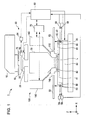
- Fig. 1 is a diagram illustrating the overall structure of an immersion exposure apparatus.
- Fig. 2 is a diagram illustrating an example of a conventional stage structure.
- Fig. 3 is a diagram illustrating a state of the conventional stage structure in a stage-switching operation.
- Fig. 4 is a diagram illustrating a locus of an immersion area in the stage structure.
- Fig. 5 is another diagram illustrating a locus of the immersion area in the stage structure.
- Fig. 6 is a diagram illustrating an example of the order of exposure.
- Fig. 7 is a graph illustrating the relationship between the moving distance of the stage, the liquid repellency, and the limit velocity.
- Fig. 8 is a diagram illustrating a stage structure according to a first embodiment of the present invention.
- Fig. 9 is a diagram illustrating an example of the order of exposure.
- Fig. 10 is a diagram illustrating a state of the stage structure according to the first embodiment in a stage-switching operation.
- Fig. 11 is a diagram illustrating an example of a state of the stage structure according to the first embodiment.
- Fig. 12 is a diagram illustrating another example of the order of exposure.
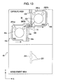
- Fig. 13 is a diagram illustrating another state of the stage structure according to the first embodiment in the stage-switching operation.
- Fig. 14 is a diagram illustrating a state of a stage structure according to a second embodiment of the present invention in a stage-switching operation.
- Fig. 15 is a diagram illustrating another state of the stage structure according to the second embodiment in the stage-switching operation.
- Fig. 16 is a diagram illustrating a state of a stage structure according to a third embodiment of the present invention in a stage-switching operation.
- Fig. 17 is a diagram illustrating another state of the stage structure according to the third embodiment in the stage-switching operation.
- Fig. 18 is a diagram illustrating a state of a stage structure according to a fourth embodiment of the present invention in a stage-switching operation.
- Fig. 19 is a diagram illustrating another state of the stage structure according to the fourth embodiment in the stage-switching operation.
- Fig. 20 is a diagram illustrating the side of the stage structure according to the fourth embodiment.
- Fig. 21 is another diagram illustrating the side of the stage structure according to the fourth embodiment.
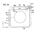
- Fig. 22 is a diagram illustrating a state of a stage structure according to a fifth embodiment of the present invention in a stage-switching operation.
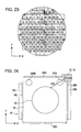
- Fig. 23 is a diagram illustrating an example of example of the order of exposure.
- Fig. 24 is another diagram illustrating a locus of an immersion area in the stage structure according to the fifth embodiment.
- Fig. 25 is a diagram illustrating a locus of an immersion area in a stage structure according to a sixth embodiment of the present invention.
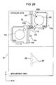
- Fig. 26 is another diagram illustrating a locus of an immersion area in the stage structure according to the sixth embodiment.
- Fig. 27 is a diagram illustrating a locus of an immersion area in a stage structure according to an seventh embodiment of the present invention.
- Fig. 28 is another diagram illustrating a locus of an immersion area in the stage structure according to the eighth embodiment.
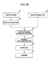
- Fig. 29 is a flowchart of a process of manufacturing a device (semiconductor chips such as IC and LSI, LCD, CCD, etc.).
- Fig. 30 is a detailed flowchart of wafer process performed in step 4 in Fig. 29 .
- Fig. 1 is a schematic sectional view illustrating an immersion exposure apparatus 1 according to the first embodiment.
- the immersion exposure apparatus 1 includes a projection optical system 30 including a final lens (final optical element) having a bottom surface facing the substrate 40.
- the immersion exposure apparatus 1 is an immersion projection exposure apparatus which projects (transfers) a circuit pattern from a reticle 20 onto the substrate 40 through liquid L supplied between the bottom surface of the final lens and the substrate 40. Either of the step-and-repeat method and the step-and-scan method can be used as the exposure method.
- the immersion exposure apparatus 1 includes an illumination device 10, a masking blade 15, a reticle stage 25 on which the reticle 20 is mounted, and the projection optical system 30.
- the immersion exposure apparatus 1 also includes the substrate 40, an auxiliary member (hereinafter called a flush plate) 41 having a surface on the same horizontal plane as the substrate 40, and a wafer stage 45 on which the substrate 40 and the flush plate 41 are disposed.
- the immersion exposure apparatus 1 also includes a measurement unit 50 (52, 53, 54, 55, 56, and 58) for measuring the position of the stage 25, a stage control unit 60, an immersion control unit 70, a liquid supply-recovery device 100 (110, 140, and 160).
- the flush plate 41 is formed separately from the wafer stage 45 in Fig. 1 , they may also have an integral structure according to the present invention.
- the stage control unit 60 drives the reticle stage 25 and the wafer stage 45 on the basis of outputs from the measurement unit 50 including interferometers (54 and 58) and reflective mirrors (52, 53, and 56).
- the immersion control unit 70 receives information including the current position, velocity, acceleration, target position, moving direction, etc., of the wafer stage 45 from the stage control unit 60 and controls the immersion exposure operation on the basis of the thus-received information.
- the immersion control unit 70 issues control commands for switching between supply and recovery of the liquid L, stopping the operation of supplying or recovering the liquid L, controlling the amount of liquid L to be supplied or recovered, etc., to a liquid supply device 140 or a liquid recovery device 160 included in the liquid supply-recovery device 100.
- Liquid supply means such as immersion nozzles 110 are used for simultaneously performing supply and recovery of the liquid L.
- an area in which the liquid film is retained is hereinafter called an "immersion area").
- FIGs. 2 and 3 are diagrams illustrating a stage operation performed in an exposure apparatus which includes two wafer stages (WS1 and WS2) and which can perform wafer processes in a measurement area and an exposure area in parallel.
- the first stage WS1 has a projection (hatched area) in an upper right area 42a in the figure
- the second stage WS2 has a projection (hatched area) in an upper left area 42b in the figure.
- Each of these projections is a part of the flush plate, and defines an area through which an immersion area passes when the immersion area is delivered to a member outside the stage.
- a portion used for delivering the immersion area L to the member outside the stage is hereinafter called a delivery portion 43 and a portion used for receiving the immersion area L from the member outside the stage is hereinafter called a receiving portion 42.
- the receiving portion 42 serves both the function as the receiving portion 42 and the function as the delivery portion 43.
- the positional relationship between the wafer 40b and the wafer stage 45b is measured with an alignment scope 202.
- measurement of the surface shape of the wafer 40b and focus measurement along an optical axis direction are performed using a focus scope 201.
- the positions of the wafer 40a and the reticle 20 are measured, and the reticle pattern is projected onto the wafer 40a shot by shot.
- the first stage 45a (WS1) performs an operation of positioning the wafer 40a in the exposure area and the stage 45b (WS2) performs an operation of positioning the wafer 40b in the measurement area at the same time. Then, when the wafer processes are finished in both the exposure area and the measurement area, the first stage WS1 and the second stage WS2 are moved to positions where they become adjacent to each other in the X-axis direction, as shown in Fig. 3 .
- the first stage WS1 and the second stage WS2 are synchronously moved in the -X direction while a small gap of about 0.1 mm to 1 mm is maintained therebetween (see the dotted arrows), so that the immersion area is moved from the first stage WS1 to the second stage WS2.
- Areas surrounding the adjacent portions 42a and 42b of the first stage WS1 and the second stage WS2, respectively, are subjected to liquid repellent finishing, and therefore the liquid cannot easily enter the gap between the stages WS1 and WS2.
- the stage to be used in the exposure area can be switched while the liquid is continuously retained below the final lens.
- Fig. 4 shows the moving locus along which a central region of the immersion area (i.e., a region around an optical axis of the final optical element) is moved after the immersion area is moved from the first stage WS1 to the second stage WS2.
- a central region of the immersion area i.e., a region around an optical axis of the final optical element
- the immersion area moves to a first reference mark 200L (S11).
- a measurement process is performed.
- the immersion area moves to a second reference mark 200R (S12), and another measurement process is performed.
- the relative position between the reticle 20 and the second stage WS2 is calculated and a positioning reference is determined.
- the immersion area moves to a first shot area (S13), and a scanning exposure operation in the Y-axis direction is started (S14 in Fig. 6 ).
- a scanning exposure operation in the Y-axis direction is started (S14 in Fig. 6 ).
- FIGs. 4 to 6 an example of an array of exposure shot areas is shown on the wafer 40.
- the numbers in the exposure shot areas indicate the order of exposure.
- the direction of scanning exposure is defined as a column direction and a direction perpendicular thereto is defined as a row direction.
- an area in the end row and end column near the second reference mark is selected as the first shot area, as shown in Fig. 6 .
- Fig. 6 shows arrows to facilitate understanding of the order of exposure. Note, however, that the arrows do not indicate the movement of the stage during exposure.
- the liquid is moved to the delivery portion 42b (along path S15) to prepare for an operation of switching the stage to be used in the exposure operation.
- the two stages are synchronously moved again while they are positioned adjacent to each other, as shown in Fig. 3 .
- the immersion area is moved from the second stage WS2 to the first stage WS1
- the two stages are moved in the +X direction, opposite to the direction shown by the dotted arrows in Fig. 3 .
- the stage-switching operation is performed.
- Fig. 7 shows the basic relationship between the liquid repellency, the moving distance, and the limit velocity. If the moving distance is that required in the exposure operation (e.g. between adjacent die), the stage can be moved at a high velocity even when the liquid repellency is that of a wafer surface. However, if the stage is moved by a longer distance than that required in the exposure operation, as in the above-described movement (S15) performed immediately after the exposure operation, the limit velocity is considerably reduced compared to that in the exposure operation. Therefore, a long moving time is required. Such a long moving time reduces the overall productivity of the apparatus. Therefore, it is desirable to avoid such a long-distance movement in the wafer processes.
- the immersion area is moved along the substrate 40 as in the above-described movement (S15 in Fig. 5 ) performed immediately after the exposure operation, there is a relatively higher possibility that exposure defects will occur.
- the resist applied to the wafer 40 can easily react with the liquid, such as pure water, and may cause failure in the exposure operation or the development operation. Therefore, the contact area and/or contact time between the resist on the wafer 40 and the liquid is required to be as small as possible in the exposure operation.
- Embodiments of the present invention aim to address at least one of the above-described two problems.
- the first embodiment of the present invention will be described below with reference to Figs. 7 to 12 .
- structures similar to those in the above-described example in which the present invention is not applied ( Figs. 2 to 6 ) will not be explained again below.
- the present embodiment provides a delivery portion and a receiving portion on each stage for delivering and receiving the liquid.
- each stage is provided with a single receiving portion 42 that serves both the function as the receiving portion and the function as the delivery portion 43. Therefore, the above-described long-distance movement (S15) along the wafer is performed immediately after the exposure operation.
- a delivery portion 43 is independently provided near the last exposure shot area. In a normal exposure operation, the immersion area is moved to the reference mark (first reference mark) that is measured immediately after the immersion area is received. Therefore, the receiving portion 42 is disposed near the reference mark 200 measured immediately after the reception of the immersion area L.
- the receiving portion 42 is disposed on the same side as the reference mark 200 which is measured immediately after the reception of the immersion area with respect to a straight line that passes through the center of the wafer 40 and extends perpendicular to the scanning direction (Y-axis direction).
- the receiving portion 42 is also disposed on the same side as the reference mark 200 which is measured immediately after the reception of the immersion area with respect to a straight line that passes through the center of the wafer 40 and extends in a direction parallel to the scanning direction (Y-axis direction).
- the delivery portion 43 is provided at a position near the last exposure shot area.
- the shot layout and the order of exposure are determined taking various conditions into account, and are not fixed.
- the stage structure is determined on the assumption that the most common shot layout and order of exposure are used and the last shot area is on the row that is farthest from the reference marks. More specifically, when the most common order of exposure is used, the last exposure shot area is probably on the side opposite to the reference mark (second reference mark) which is measured immediately before the exposure operation with respect to the straight line that passes through the center of the wafer and extends perpendicular to the scanning direction (Y-axis direction). Therefore, the delivery portion is provided at a position near the thus-assumed last exposure shot area.
- Fig. 8 shows a locus of the immersion area moved as the stage is moved immediately after the stage positioned under the projection lens is switched from the stage WS2 to the stage WS1. More specifically, the immersion area moves from the first receiving portion 42a to the first reference mark 200Ra, where the first reference mark 200Ra is measured, and is then moved to the second reference mark 200La, where the second reference mark 200La is measured. Accordingly, the relative position between the reticle 20 and the wafer stage 45 is calculated. Then, the immersion area is moved to the first shot area on the wafer and the scanning exposure operation is performed in the Y-axis direction. More specifically, exposure is successively carried out at each of the exposure shot areas.
- the first shot area is selected so as to make the total moving distance in the exposure operation as small as possible. More specifically, the first shot area is disposed on the same side as the reference mark measured immediately before the exposure operation with respect to the straight line that passes through the center of the wafer and extends perpendicular to the scanning direction. In more detail, when the direction of scanning exposure is defined as a column direction, a shot area on the end row and end column near the reference mark 200 measured last is selected as the first shot area. For example, in the first stage WS1, the reference mark 200La which is measured immediately before the exposure operation (i.e., which is measured last) is at the upper left in Fig. 8 . Therefore, as shown in Fig.
- the shot area at the upper left corner is selected as the first shot area.
- the reference mark 200Rb which is measured last is at the upper right in Fig. 11 . Therefore, as shown in Fig. 12 , the shot area at the upper right corner is selected as the first shot area.
- the delivery portion 43a of the first stage WS1 and the receiving portion 42b of the second stage WS2 are positioned adjacent to each other in X-axis direction, as shown in Fig. 10 .
- a small gap of 1 mm or less may be provided between the adjacent portions that are subjected to liquid repellent finishing so that the liquid can be prevented from spilling from the stages when they are positioned adjacent to each other.
- an elastic member such as rubber, may be brought into physical contact between the adjacent portions.
- the two stages are synchronously moved leftward in the figure (-X direction) as shown by the dotted arrows, so that the immersion area is moved from the first stage WS1 (45a) to the second stage WS2 (45b).
- the first stage WS1 is moved to the measurement area
- the immersion area on the second stage WS2 is moved to the first reference mark 200Lb.
- the immersion area on the second stage WS2 is moved to the second reference mark 200Rb, where the second reference mark 200Rb is measured, and then the exposure operation is performed in the order shown in Fig. 12 .
- a wafer exchanging operation and various measurements for a new wafer are performed on the first stage WS1.
- the delivery portion 43b of the second stage WS2 and the receiving portion 42a of the first stage WS1 are positioned adjacent to each other in the X-axis direction, as shown in Fig. 13 .
- the two stages (WS1 and WS2) are synchronously moved rightward in the figure (+X direction) as shown by the dotted arrows, so that the immersion area is moved from the second stage WS2 to the first stage WS1.
- the moving distance by which the immersion area is moved immediately after the exposure operation can be reduced.
- the immersion area is moved along the flush plate 41 which is adapted to have a higher liquid repellency than that of the wafer 40. Therefore, the immersion area can be moved at a relatively high velocity, as is clear from the relationship shown in Fig. 7 . Therefore, the immersion area can be moved by a shorter distance at a higher velocity after the exposure operation. As a result, the moving time can be reduced compared to that of the movement denoted by S15 in Fig. 5 , and the throughput of the exposure apparatus can be increased.
- the contact area in which the immersion area comes into contact with the surface of the wafer 40 when the immersion area is moved immediately after the exposure operation can be greatly reduced.
- the wafer surface is relatively uniformly in contact with the liquid in terms of time. Therefore, exposure defects caused by reaction between the resist and the liquid can be suppressed, and the reliability of the immersion exposure apparatus can be increased.
- the two reference marks 200L and 200R are separated form each other in a direction (X-axis direction) that is perpendicular to the scanning direction (Y-axis direction).
- X-axis direction a direction that is perpendicular to the scanning direction
- Y-axis direction a positioning reference in the Z direction
- a positioning reference for inclination around the Y axis can be accurately calculated on the basis of the information obtained by measuring a plurality of reference marks 200 separated from each other in the X-axis direction.
- the measurement accuracy is increased in proportion to the distance between the reference marks 200L and 200R. Since high accuracy measurement and positioning can be achieved for the inclination around the scanning direction (Y-axis direction), focus state in the exposure slit can be made uniform in the longitudinal direction in a scanning exposure operation. In other words, the exposure accuracy of the exposure apparatus can be increased.
- each stage has the receiving portion 42 and the delivery portion 43 on projections provided at respective corners of the stage.
- the projections may also be omitted. These projections are provided to prevent interference with the interference mirrors (55 and 56) used for position measurement and optical axes of the interference mirrors. Therefore, depending on the structure of the interferometers, the immersion area can be delivered and received without providing the projections.
- the stages are free from the projections at the corners. Structures other than the presence/absence of the projections are similar to those in the first embodiment, and detailed explanations thereof are thus omitted.
- Figs. 14 and 15 are diagrams illustrating the structure of the present embodiment corresponding to Figs. 10 and 13 , respectively, of the first embodiment.
- a receiving portion 42 and a delivery portion 43 are provided on each of the right side of the first stage WS1 and on the left side of the second stage WS2.
- Fig. 14 shows the state in which the immersion area is moved from the first stage WS1 to the second stage WS2
- Fig. 15 shows the state in which the immersion area is moved from the second stage WS2 to the first stage WS1.
- the manner in which the immersion area is moved as the stages are moved is similar to that in the first embodiment.
- the receiving portion 42 and the delivery portion 43 can be disposed on a straight line connecting the expected last exposure shot area and the reference marks 200.
- the distance by which the immersion area is moved after the exposure can be reduced compared to that in the first embodiment, and the throughput can be further increased.
- the immersion area is not moved along the wafer 40 after the exposure operation. Therefore, exposure defects caused by reaction between the resist and the liquid can be suppressed.
- the two stages are synchronously moved in the X-axis direction to deliver and receive the immersion area.
- the structure of the present invention can also be applied to a system in which the immersion area is delivered and received by a synchronous movement in the Y-axis direction.
- Figs. 16 and 17 are diagrams illustrating the present embodiment in which each stage has the receiving portion 42 and the delivery portion 43a on the sides facing each other in the Y-axis direction.
- Fig. 16 shows the state in which the immersion area is moved from the first stage WS1 to the second stage WS2.
- the two stages are positioned adjacent to each other in the Y-axis direction, and are synchronously moved in the +Y direction so as to move the immersion area L.
- the receiving portion 42 is disposed near the reference marks 200 and the delivery portion 43 is disposed near the last exposure shot area.
- the receiving portion 42 is disposed on a side of each stage 45 in the Y-axis direction at a position near the reference marks 200. More specifically, the receiving portion 42 is disposed near the reference mark 200 which is measured first after the immersion area is received. Accordingly, the moving time of the stage can be further reduced.
- the delivery portion 43 is disposed on the other side of the stage 45 in the Y-axis direction, that is, on the side far from the reference marks 200 at a position near the expected last shot area. Therefore, the moving time of each stage 45 can be further reduced and the throughput can be increased.
- the immersion area is not moved along the wafer 40 after the exposure operation. Therefore, exposure defects caused by reaction between the resist and the liquid can be suppressed.
- the reference marks 200 are separated from each other in a direction perpendicular to the scanning direction, the positioning accuracy for the inclination around the scanning direction is increased. Therefore, the exposure accuracy is increased.
- a fourth embodiment will be described below with reference to Figs. 18 and 19 .
- the fourth embodiment is characterized in that the arrangement positions of the reference marks 200 are changed from those in the first embodiment. Accordingly, the arrangement of the two stages 45 in the process of moving the immersion area between the stages is also changed.
- the present embodiment will be described in detail below.
- Fig. 18 corresponds to Fig. 10 according to the first embodiment, and shows the state in which the immersion area is moved from the first stage WS1 to the second stage WS2.
- the difference between Fig. 18 and Fig. 10 will be described below. That is, in Fig. 18 , the reference marks 200 of the second stage WS2 are positioned on the side opposite to the reference marks 200 of the first stage WS1 with respect to a line extending through the center of the wafer in a direction (X-axis direction) perpendicular to the scanning direction.
- the reference marks 200Ra and 200La on the first stage WS1 are positioned on the +Y side of the stage WS1, whereas the reference marks 200Rb and 200Lb of the second stage WS2 are positioned on the -Y side of the stage WS2.
- the reference mark which is measured first after the immersion area is received is the reference mark 200Ra on the +X side.
- the reference mark which is measured first after the immersion area is received is the reference mark 200Lb on the -X side.
- Fig. 19 corresponds to Fig. 13 according to the first embodiment, and illustrates the state in which the immersion area is moved from the second stage WS2 to the first stage WS1.
- the reference marks 200 are arranged as described above, when the immersion area is moved, it is not necessary to place the first stage WS1 and the second stage WS2 at positions adjacent to each other but shifted from each other in the Y-axis direction as shown in Fig. 10 . Therefore, when the immersion area is moved between the stages 45, it is not necessary to change the positional relationship between the stages 45 depending on the moving direction of the immersion area as shown Figs. 10 and 11 . Therefore, the movement of the stages 45 is simplified and the stages 45 can be easily controlled. In addition, when the immersion area is moved between the stages 45, the same pair of portions (42a and 43b, 43a and 42b) are always positioned adjacent to each other. Therefore, the following structure can be applied.
- the stages 45 are moved while being positioned adjacent to each other to continuously retain the immersion area on the stages 45, there is a risk that the liquid will spill from the stages 45 when a small gap is provided therebetween. Therefore, surfaces around the adjacent portions (42 and 43) are subjected to liquid repellent finishing, so that the liquid can be prevented from entering the gap due to capillarity action.
- the adjacent edges of portions 42 and 43 can be tapered and superimposed in accordance with the moving direction of the immersion area (moving direction of the stages) so that the liquid can be more reliably prevented from spilling out of the stages 45.
- Fig. 20 is a sectional view of the stages in the state in which the immersion area is moved from the first stage WS1 to the second stage WS2. Edges of the adjacent portions (42 and 43) are tapered in accordance with the moving direction of the immersion area relative to the stages. In this case, the immersion area L cannot easily enter the gap between the stages.
- Fig. 21 is a sectional view of the stages in the state in which the immersion area is moved from the second stage WS2 to the first stage WS1. The direction of inclination at the edges of the adjacent portions (42 and 43) is opposite to that shown in Fig. 20 because the moving direction of the immersion area (moving direction of the stages) is opposite to that in Fig. 20 .
- This structure can be applied because when the immersion area is moved between the stages 45, each pair of the adjacent portions (the receiving portion 42 and the delivery portion 43) is always in the same state irrespective of the moving direction of the immersion area.
- the adjacent portions (the receiving portion 42 and the delivery portion 43) of the stages cannot be inclined because the inclination directions thereof do not always match.
- the low-velocity, long-distance movement can be eliminated and the liquid L is suppressed from coming into contact with the wafer 40 after the exposure operation. Therefore, the throughput can be increased and the occurrence of exposure defects can be reduced.
- the reference marks 200 are separated from each other in a direction perpendicular to the scanning direction, the positioning accuracy for the inclination around the scanning direction is increased. Therefore, the exposure accuracy is increased.
- Figs. 22 to 24 illustrate the structure of a fifth embodiment in which the moving times before and after the exposure operation are reduced by changing the order of exposure.
- the structure of the stages 45 according to the present embodiment is similar to that of the conventional system shown in Fig. 2 . However, the order of exposure is different from that in the conventional system. This will be described in more detail.
- the immersion area received by the receiving portion 42 is moved to the first reference mark 200L, where the first reference mark 200L is measured.
- the immersion area is moved to the second reference mark, where the second reference mark is measured.
- the exposure operation is started. Referring to Fig. 23 , first, shot areas in about one-half of the wafer on the -X side thereof are subjected to exposure.
- the exposure area is moved along the bottom row into the +X side of the wafer, and returns to the top row.
- the essence of this order of exposure is that the first shot area and the last shot area are on the same side with respect to a line that passes through the center of the wafer 40 and extends perpendicular to the scanning direction. Therefore, the present invention is not limited to the order of exposure shown in Fig. 23 . More specifically, in the conventional order of exposure, the first shot area and the last shot area are on the rows at the opposite ends when the scanning direction is defined as the column direction, and are never positioned on the same row. Therefore, the distance by which the immersion area is moved after the exposure operation is long (S15 in Fig. 5 ) and the throughput cannot be increased.
- the order of exposure is determined such that the first shot area and the last shot area can be placed on the same row. Therefore, the distance by which the immersion area is moved after the exposure operation can be reduced ( Fig. 24 ) and the throughput can be increased. Also in the present embodiment, like in the other embodiments, the liquid comes into contact with the wafer a reduced amount, and so the occurrence of exposure defects can be reduced.
- Figs. 25 and 26 show the structure of a sixth embodiment in which only one reference mark 200 is provided.
- the reference mark is defined as a member including one or more measurement marks used for measuring a positioning reference.
- Fig. 25 shows the state in which the immersion area L is moved from the first stage WS1 to the second stage WS2.
- the solid arrow shows the moving locus of the immersion area, and the dashed arrows show the moving direction of the two stages 45 in this process.
- the immersion area moves between the stages 45 by passing through the delivery portion 43a of the first stage WS1 and the receiving portion 42b of the second stage WS2.
- the immersion area is moved to the reference mark 200b of the second stage WS2.
- the reference mark 200b is measured and the exposure operation is performed.
- the delivery portion 43b of the second stage and the receiving portion 42a of the first stage are positioned adjacent to each other, and the immersion area is moved from the second stage WS2 to the first stage WS1.
- the reference mark on the first stage is measured and the exposure operation is performed in a similar manner, and the immersion area is moved between the stages.
- a plurality of wafers 40 can be processed.
- the immersion area is moved between a plurality of wafer stages (WS1, WS2) that can be used in the exposure operation.
- the present invention is characterized in the relative positions between the receiving portion and the delivery portion in at least one wafer stage that can be used in the exposure operation. Therefore, there is no limit to a member to which or from which the immersion area is moved, and the member to which or from which the immersion area is moved is, of course, not limited to a wafer stage that can be used in the exposure operation.
- Figs. 27 and 28 illustrate the structure of a seventh embodiment in which a member to which and from which the immersion area is moved is an immersion-area standby stage 45C. An exposure apparatus shown in Figs.
- FIG. 27 and 28 includes a stage 45a that can be used in the exposure operation of the substrate 40 and the immersion standby stage 45C used for temporarily holding the immersion area L when the stage 45a is moved to the measurement area.
- Fig. 27 shows the state in which the immersion area is moved from the wafer stage 45a to the immersion standby stage 45C.
- the solid arrow shows the moving locus of the immersion area, and the dashed arrows show the moving direction of the two stages in this process. Similar to the other embodiments, the two stages 45 are synchronously moved while being positioned adjacent to each other or in contact with each other.
- the delivery portion 43 from which the immersion area is moved is disposed on the side opposite to the reference mark 200La, which is measured immediately before the exposure, with respect to a line that passes through the center of the wafer and extends perpendicular to the scanning direction.
- the wafer stage 45a is moved to the measurement area and various processes are performed (not shown) while the immersion standby stage 45C is in a steady state. After the processes are finished in the measurement area, the wafer stage 45a is positioned adjacent to the immersion standby stage 45C or is brought into contact with the immersion standby stage 45C, as shown in Fig.
- the receiving portion 42 through which the immersion area is moved is disposed in a region near the reference mark 200Ra that is measured first after the immersion area is received.
- the region near the reference mark 200Ra is defined as an area on the same side as the reference mark 200Ra with respect to at least one of a line that passes through the center of the wafer 40 and extends perpendicular to the scanning direction and a line that passes through the center of the wafer 40 and extends parallel to the scanning direction.
- Fig. 29 is a flowchart showing processes for manufacturing devices (for example, semiconductor chips such as ICs and LSIs, LCDs, and CCDs).
- a manufacturing method of semiconductor chips will be described.
- Step S1 circuit design
- Step S2 reticle fabrication
- Step S3 wafer fabrication
- a wafer is formed of a material such as silicon.
- Step S4 wafer process
- Step S5 wafer process
- Step S5 semiconductor chips are formed from the wafer obtained in Step S4. This process includes an assembly process (dicing and bonding) and a packaging process (chip sealing).
- Step S6 inspection
- the semiconductor chips obtained in Step S5 are tested for, for example, operation and durability. The semiconductor chips are thus completed through the above processes, and are then shipped (Step S7).
- Fig. 30 is a detailed flowchart of the wafer process performed in Step S4 shown in Fig. 29 .
- Step S11 oxidation
- Step S12 CVD
- Step S13 electrode formation
- Step S14 ion implantation
- Step S15 resist processing
- Step S16 exposure
- Step S17 development
- Step S18 etching
- Step S19 resist removal
- the resist which becomes unnecessary after etching, is removed.
- a multi-layer circuit pattern is formed on the wafer.
- the device manufacturing method using the immersion exposure apparatus 1 and the device obtained by the manufacturing method also constitute an aspect of the present invention.
Landscapes
- Physics & Mathematics (AREA)
- General Physics & Mathematics (AREA)
- Exposure And Positioning Against Photoresist Photosensitive Materials (AREA)
- Exposure Of Semiconductors, Excluding Electron Or Ion Beam Exposure (AREA)
- Container, Conveyance, Adherence, Positioning, Of Wafer (AREA)
Claims (8)
- Scanimmersionsbelichtungsvorrichtung (1), umfassend:eine Projektionsoptik (30);einen Tisch (45), der konfiguriert ist, um sich mit einem auf ihm angebrachten Substrat (40) zu bewegen; undeine Flüssigkeitszuführeinrichtung (110), die konfiguriert ist, um einem lokalen Bereich zwischen der Projektionsoptik (30) und dem Tisch (45) Flüssigkeit zuzuführen und die zugeführte Flüssigkeit zurückzugewinnen,wobei der Tisch (45) enthälteinen Transferabschnitt (43), der konfiguriert ist, um den mit der Flüssigkeit in Kontakt befindlichen lokalen Bereich in die Lage zu versetzen, vom Tisch (45a) zu einem weiteren Tisch (45b) bewegt zu werden, undeine oder mehrere auf dem Tisch (45) vorgesehene Referenzmarkierungen (200) zum Positionieren des Tisches (45) bezüglich einer Maske (20), dadurch gekennzeichnet, dassim Betrieb die Scanimmersionsbelichtungsvorrichtung derart ausgebildet ist, dass der Transferabschnitt (43a) und eine direkt vor der Belichtung gemessene Referenzmarkierung (200Ra) der einen oder mehreren Referenzmarkierungen an gegenüberliegenden Seiten einer ersten Linie angeordnet sind, die durch das Zentrum des Substrats (40) verläuft und sich senkrecht zu einer Scanrichtung erstreckt.
- Belichtungsvorrichtung nach Anspruch 1, wobei der Tisch (45) weiter einen Aufnahmeabschnitt (42) zum Aufnehmen des Bereichs von einem weiteren Mittel enthält, und
wobei der Aufnahmeabschnitt (42) bezüglich der ersten Linie auf derselben Seite wie eine direkt nach Aufnahme des Bereichs gemessene Referenzmarkierung der einen oder mehreren Referenzmarkierungen (200) angeordnet ist. - Belichtungsvorrichtung nach Anspruch 2, wobei der Aufnahmeabschnitt (42) bezüglich einer zweiten Linie, die durch das Zentrum des Substrats (40) verläuft und sich parallel zur Scanrichtung erstreckt, auf derselben Seite wie die direkt nach Aufnahme des Bereichs gemessene Referenzmarkierung der einen oder mehreren Referenzmarkierungen (200) angeordnet ist.
- Belichtungsvorrichtung nach einem der vorhergehenden Ansprüche, wobei die eine oder mehreren Referenzmarkierungen (200) mehrere Referenzmarkierungen (200) umfassen, wobei die Referenzmarkierungen (200) in einer Richtung senkrecht zur Scanrichtung voneinander beabstandet sind.
- Belichtungsverfahren, das die Belichtungsvorrichtung nach einem der Ansprüche 1 bis 4 verwendet, wobei sich ein als letztes zu belichtender Belichtungsbereich auf dem Substrat (40) bezüglich der ersten Linie auf der Seite gegenüber der einen direkt vor der Belichtung gemessenen Referenzmarkierung der einen oder mehreren Referenzmarkierungen (200) befindet.
- Belichtungsverfahren nach Anspruch 5, wobei sich ein als erstes zu belichtender Belichtungsbereich auf dem Substrat (40) bezüglich der ersten Linie auf derselben Seite wie die eine direkt vor der Belichtung gemessene Referenzmarkierung der einen oder mehreren Referenzmarkierungen (200) befindet.
- Belichtungsverfahren für eine Scanimmersionsbelichtungsvorrichtung (1) enthaltend eine Projektionsoptik (30), einen Tisch (45), der konfiguriert ist, um sich mit einem auf ihm angebrachten Substrat (40) zu bewegen, und eine Flüssigkeitszuführeinrichtung, die konfiguriert ist, um einem lokalen Bereich zwischen der Projektionsoptik (30) und dem Tisch (45) Flüssigkeit zuzuführen und die zugeführte Flüssigkeit zurückzugewinnen, wobei der Tisch (45) einen Transfer-/Aufnahmeabschnitt enthält, um den mit der Flüssigkeit in Kontakt befindlichen lokalen Bereich vom Tisch (45) zu einem weiteren Tisch (45b) zu transferieren, und den Bereich von einem weiteren Mittel aufzunehmen, wobei das Verfahren folgende Schritte umfasst:Einrichten eines als erstes zu belichtenden Belichtungsbereichs auf dem Substrat (40) und eines als letztes zu belichtenden Belichtungsbereichs auf dem Substrat (40) auf derselben Seite wie den Transfer-/Aufnahmeabschnitt bezüglich einer Linie, die durch das Zentrum des Substrats (40) verläuft und sich senkrecht zur Scanrichtung erstreckt; undBelichten des Substrats (40) auf der Grundlage der eingerichteten Belichtungsbereiche.
- Verwendung einer Belichtungsvorrichtung nach einem der Ansprüche 1 bis 4 in einem Device-Herstellungsverfahren.
Applications Claiming Priority (1)
| Application Number | Priority Date | Filing Date | Title |
|---|---|---|---|
| JP2006312928A JP5089143B2 (ja) | 2006-11-20 | 2006-11-20 | 液浸露光装置 |
Publications (3)
| Publication Number | Publication Date |
|---|---|
| EP1923744A2 EP1923744A2 (de) | 2008-05-21 |
| EP1923744A3 EP1923744A3 (de) | 2011-02-09 |
| EP1923744B1 true EP1923744B1 (de) | 2013-09-18 |
Family
ID=39226587
Family Applications (1)
| Application Number | Title | Priority Date | Filing Date |
|---|---|---|---|
| EP07121119.7A Ceased EP1923744B1 (de) | 2006-11-20 | 2007-11-20 | Immersionsbelichtungsgerät und Belichtungsverfahren |
Country Status (5)
| Country | Link |
|---|---|
| US (1) | US20080117398A1 (de) |
| EP (1) | EP1923744B1 (de) |
| JP (1) | JP5089143B2 (de) |
| KR (1) | KR101088672B1 (de) |
| TW (1) | TWI376577B (de) |
Families Citing this family (9)
| Publication number | Priority date | Publication date | Assignee | Title |
|---|---|---|---|---|
| KR101419196B1 (ko) * | 2006-09-29 | 2014-07-15 | 가부시키가이샤 니콘 | 노광 장치 및 노광 방법, 그리고 디바이스 제조 방법 |
| US8279399B2 (en) | 2007-10-22 | 2012-10-02 | Nikon Corporation | Exposure apparatus, exposure method, and device manufacturing method |
| WO2009060585A1 (ja) * | 2007-11-07 | 2009-05-14 | Nikon Corporation | 露光装置及び露光方法、並びにデバイス製造方法 |
| NL2003575A (en) | 2008-10-29 | 2010-05-03 | Asml Netherlands Bv | Lithographic apparatus and device manufacturing method. |
| EP2221669A3 (de) | 2009-02-19 | 2011-02-09 | ASML Netherlands B.V. | Lithografische Vorrichtung, Verfahren zum Steuern der Vorrichtung und Verfahren zur Herstellung eines Artikels |
| NL2005322A (en) | 2009-09-11 | 2011-03-14 | Asml Netherlands Bv | A shutter member, a lithographic apparatus and device manufacturing method. |
| JP2013004942A (ja) * | 2011-06-22 | 2013-01-07 | Renesas Electronics Corp | 半導体装置の製造方法 |
| JP6362312B2 (ja) * | 2013-09-09 | 2018-07-25 | キヤノン株式会社 | 露光装置、それを用いたデバイスの製造方法 |
| JP6440878B2 (ja) * | 2018-02-05 | 2018-12-19 | キヤノン株式会社 | 露光装置、およびそれを用いたデバイスの製造方法 |
Family Cites Families (23)
| Publication number | Priority date | Publication date | Assignee | Title |
|---|---|---|---|---|
| US5243195A (en) * | 1991-04-25 | 1993-09-07 | Nikon Corporation | Projection exposure apparatus having an off-axis alignment system and method of alignment therefor |
| JPH09115826A (ja) * | 1995-10-19 | 1997-05-02 | Nikon Corp | 露光データ作成方法並びに露光方法及び露光装置 |
| EP0843221B1 (de) * | 1996-11-14 | 2004-05-06 | Nikon Corporation | Projektionsbelichtungsapparat |
| DE60335595D1 (de) * | 2002-11-12 | 2011-02-17 | Asml Netherlands Bv | Lithographischer Apparat mit Immersion und Verfahren zur Herstellung einer Vorrichtung |
| JP4645027B2 (ja) | 2002-12-10 | 2011-03-09 | 株式会社ニコン | 露光装置及び露光方法、デバイス製造方法 |
| US7242455B2 (en) * | 2002-12-10 | 2007-07-10 | Nikon Corporation | Exposure apparatus and method for producing device |
| KR101159564B1 (ko) * | 2003-04-11 | 2012-06-25 | 가부시키가이샤 니콘 | 액침 리소그래피 머신에서 웨이퍼 교환동안 투영 렌즈 아래의 갭에서 액침액체를 유지하는 장치 및 방법 |
| JP2005005295A (ja) | 2003-06-09 | 2005-01-06 | Nikon Corp | ステージ装置及び露光装置 |
| KR101381563B1 (ko) * | 2003-08-21 | 2014-04-04 | 가부시키가이샤 니콘 | 노광 장치, 노광 방법 및 디바이스 제조 방법 |
| JP3870182B2 (ja) | 2003-09-09 | 2007-01-17 | キヤノン株式会社 | 露光装置及びデバイス製造方法 |
| US7589822B2 (en) * | 2004-02-02 | 2009-09-15 | Nikon Corporation | Stage drive method and stage unit, exposure apparatus, and device manufacturing method |
| US7898642B2 (en) * | 2004-04-14 | 2011-03-01 | Asml Netherlands B.V. | Lithographic apparatus and device manufacturing method |
| JP2005322755A (ja) * | 2004-05-07 | 2005-11-17 | Nikon Corp | 誤差検出方法、位置合わせ方法、露光方法 |
| US7583357B2 (en) * | 2004-11-12 | 2009-09-01 | Asml Netherlands B.V. | Lithographic apparatus and device manufacturing method |
| CN101258581B (zh) * | 2005-09-09 | 2011-05-11 | 株式会社尼康 | 曝光装置及曝光方法以及设备制造方法 |
| US7310132B2 (en) * | 2006-03-17 | 2007-12-18 | Asml Netherlands B.V. | Lithographic apparatus and device manufacturing method |
| US8330936B2 (en) * | 2006-09-20 | 2012-12-11 | Asml Netherlands B.V. | Lithographic apparatus and device manufacturing method |
| KR101419196B1 (ko) * | 2006-09-29 | 2014-07-15 | 가부시키가이샤 니콘 | 노광 장치 및 노광 방법, 그리고 디바이스 제조 방법 |
| JP2008124194A (ja) * | 2006-11-10 | 2008-05-29 | Canon Inc | 液浸露光方法および液浸露光装置 |
| JP2008124219A (ja) * | 2006-11-10 | 2008-05-29 | Canon Inc | 液浸露光装置 |
| JP2008124379A (ja) * | 2006-11-15 | 2008-05-29 | Nikon Corp | 露光装置及び露光方法、並びにデバイス製造方法 |
| US8040490B2 (en) * | 2006-12-01 | 2011-10-18 | Nikon Corporation | Liquid immersion exposure apparatus, exposure method, and method for producing device |
| US8013975B2 (en) * | 2006-12-01 | 2011-09-06 | Nikon Corporation | Exposure apparatus, exposure method, and method for producing device |
-
2006
- 2006-11-20 JP JP2006312928A patent/JP5089143B2/ja not_active Expired - Fee Related
-
2007
- 2007-11-09 KR KR1020070114086A patent/KR101088672B1/ko not_active Expired - Fee Related
- 2007-11-12 TW TW096142688A patent/TWI376577B/zh not_active IP Right Cessation
- 2007-11-14 US US11/940,143 patent/US20080117398A1/en not_active Abandoned
- 2007-11-20 EP EP07121119.7A patent/EP1923744B1/de not_active Ceased
Also Published As
| Publication number | Publication date |
|---|---|
| TW200839456A (en) | 2008-10-01 |
| TWI376577B (en) | 2012-11-11 |
| JP5089143B2 (ja) | 2012-12-05 |
| EP1923744A2 (de) | 2008-05-21 |
| EP1923744A3 (de) | 2011-02-09 |
| US20080117398A1 (en) | 2008-05-22 |
| KR20080045618A (ko) | 2008-05-23 |
| JP2008130745A (ja) | 2008-06-05 |
| KR101088672B1 (ko) | 2011-12-01 |
Similar Documents
| Publication | Publication Date | Title |
|---|---|---|
| EP1923744B1 (de) | Immersionsbelichtungsgerät und Belichtungsverfahren | |
| US7382434B2 (en) | Exposure apparatus and device manufacturing method | |
| US7518708B2 (en) | Liquid-immersion exposure method and liquid-immersion exposure apparatus | |
| KR100975256B1 (ko) | 노광방법, 노광장치 및 디바이스 제조방법 | |
| KR20130010039A (ko) | 노광 장치 및 디바이스 제조 방법 | |
| TWI471900B (zh) | Exposure method, exposure apparatus, exposure system, and device manufacturing method | |
| KR100882046B1 (ko) | 노광장치 및 디바이스의 제조방법 | |
| JPH11186154A (ja) | 投影露光装置および方法 | |
| US6399283B1 (en) | Exposure method and aligner | |
| US6163369A (en) | Plane position detecting method and exposing method and exposure apparatus using same | |
| JP3962736B2 (ja) | 露光装置およびデバイス製造方法 | |
| JP2009094256A (ja) | 露光方法、露光装置およびデバイス製造方法 | |
| US6559927B1 (en) | Gap adjusting method in exposure apparatus | |
| US6256085B1 (en) | Exposure apparatus | |
| JP2007281308A (ja) | 液浸露光装置 | |
| KR20010015157A (ko) | 노광장치 및 디바이스의 제조방법 | |
| JP2008218976A (ja) | 露光装置 | |
| JP5087907B2 (ja) | 電子部品の製造方法及びデバイス製造方法並びに電子部品の製造システム | |
| US6856404B2 (en) | Scanning exposure method and apparatus, and device manufacturing method using the same | |
| JP2007273653A (ja) | 露光装置及び露光方法 | |
| JP2000182936A (ja) | 露光装置およびデバイス製造方法 |
Legal Events
| Date | Code | Title | Description |
|---|---|---|---|
| PUAI | Public reference made under article 153(3) epc to a published international application that has entered the european phase |
Free format text: ORIGINAL CODE: 0009012 |
|
| AK | Designated contracting states |
Kind code of ref document: A2 Designated state(s): AT BE BG CH CY CZ DE DK EE ES FI FR GB GR HU IE IS IT LI LT LU LV MC MT NL PL PT RO SE SI SK TR |
|
| AX | Request for extension of the european patent |
Extension state: AL BA HR MK RS |
|
| PUAL | Search report despatched |
Free format text: ORIGINAL CODE: 0009013 |
|
| AK | Designated contracting states |
Kind code of ref document: A3 Designated state(s): AT BE BG CH CY CZ DE DK EE ES FI FR GB GR HU IE IS IT LI LT LU LV MC MT NL PL PT RO SE SI SK TR |
|
| AX | Request for extension of the european patent |
Extension state: AL BA HR MK RS |
|
| 17P | Request for examination filed |
Effective date: 20110809 |
|
| RIN1 | Information on inventor provided before grant (corrected) |
Inventor name: EMOTO, KEIJI |
|
| AKX | Designation fees paid |
Designated state(s): DE GB NL |
|
| 17Q | First examination report despatched |
Effective date: 20120706 |
|
| GRAP | Despatch of communication of intention to grant a patent |
Free format text: ORIGINAL CODE: EPIDOSNIGR1 |
|
| INTG | Intention to grant announced |
Effective date: 20130418 |
|
| GRAS | Grant fee paid |
Free format text: ORIGINAL CODE: EPIDOSNIGR3 |
|
| GRAA | (expected) grant |
Free format text: ORIGINAL CODE: 0009210 |
|
| AK | Designated contracting states |
Kind code of ref document: B1 Designated state(s): DE GB NL |
|
| REG | Reference to a national code |
Ref country code: GB Ref legal event code: FG4D |
|
| REG | Reference to a national code |
Ref country code: DE Ref legal event code: R096 Ref document number: 602007032899 Country of ref document: DE Effective date: 20131107 |
|
| REG | Reference to a national code |
Ref country code: NL Ref legal event code: VDEP Effective date: 20130918 |
|
| PG25 | Lapsed in a contracting state [announced via postgrant information from national office to epo] |
Ref country code: NL Free format text: LAPSE BECAUSE OF FAILURE TO SUBMIT A TRANSLATION OF THE DESCRIPTION OR TO PAY THE FEE WITHIN THE PRESCRIBED TIME-LIMIT Effective date: 20130918 |
|
| REG | Reference to a national code |
Ref country code: DE Ref legal event code: R097 Ref document number: 602007032899 Country of ref document: DE |
|
| PLBE | No opposition filed within time limit |
Free format text: ORIGINAL CODE: 0009261 |
|
| STAA | Information on the status of an ep patent application or granted ep patent |
Free format text: STATUS: NO OPPOSITION FILED WITHIN TIME LIMIT |
|
| 26N | No opposition filed |
Effective date: 20140619 |
|
| GBPC | Gb: european patent ceased through non-payment of renewal fee |
Effective date: 20131218 |
|
| REG | Reference to a national code |
Ref country code: DE Ref legal event code: R097 Ref document number: 602007032899 Country of ref document: DE Effective date: 20140619 |
|
| PG25 | Lapsed in a contracting state [announced via postgrant information from national office to epo] |
Ref country code: GB Free format text: LAPSE BECAUSE OF NON-PAYMENT OF DUE FEES Effective date: 20131218 |
|
| PGFP | Annual fee paid to national office [announced via postgrant information from national office to epo] |
Ref country code: DE Payment date: 20161130 Year of fee payment: 10 |
|
| REG | Reference to a national code |
Ref country code: DE Ref legal event code: R119 Ref document number: 602007032899 Country of ref document: DE |
|
| PG25 | Lapsed in a contracting state [announced via postgrant information from national office to epo] |
Ref country code: DE Free format text: LAPSE BECAUSE OF NON-PAYMENT OF DUE FEES Effective date: 20180602 |