EP1923657B1 - A compact, fully stabilised, four axes, remote weapon station with independent line of sight - Google Patents
A compact, fully stabilised, four axes, remote weapon station with independent line of sight Download PDFInfo
- Publication number
- EP1923657B1 EP1923657B1 EP06124200.4A EP06124200A EP1923657B1 EP 1923657 B1 EP1923657 B1 EP 1923657B1 EP 06124200 A EP06124200 A EP 06124200A EP 1923657 B1 EP1923657 B1 EP 1923657B1
- Authority
- EP
- European Patent Office
- Prior art keywords
- weapon
- sight
- remote
- axis
- sight unit
- Prior art date
- Legal status (The legal status is an assumption and is not a legal conclusion. Google has not performed a legal analysis and makes no representation as to the accuracy of the status listed.)
- Revoked
Links
- 230000001419 dependent effect Effects 0.000 claims description 3
- 230000002093 peripheral effect Effects 0.000 description 6
- 230000004438 eyesight Effects 0.000 description 4
- 238000010304 firing Methods 0.000 description 3
- 230000000087 stabilizing effect Effects 0.000 description 3
- 230000009286 beneficial effect Effects 0.000 description 2
- 238000004904 shortening Methods 0.000 description 2
- 230000000007 visual effect Effects 0.000 description 2
- 230000004308 accommodation Effects 0.000 description 1
- 230000000694 effects Effects 0.000 description 1
- 238000005286 illumination Methods 0.000 description 1
- 238000009434 installation Methods 0.000 description 1
- 238000000034 method Methods 0.000 description 1
- 230000008092 positive effect Effects 0.000 description 1
- 230000003019 stabilising effect Effects 0.000 description 1
- 230000008685 targeting Effects 0.000 description 1
Images

Classifications
-
- F—MECHANICAL ENGINEERING; LIGHTING; HEATING; WEAPONS; BLASTING
- F41—WEAPONS
- F41G—WEAPON SIGHTS; AIMING
- F41G3/00—Aiming or laying means
- F41G3/14—Indirect aiming means
- F41G3/16—Sighting devices adapted for indirect laying of fire
- F41G3/165—Sighting devices adapted for indirect laying of fire using a TV-monitor
-
- F—MECHANICAL ENGINEERING; LIGHTING; HEATING; WEAPONS; BLASTING
- F41—WEAPONS
- F41G—WEAPON SIGHTS; AIMING
- F41G3/00—Aiming or laying means
- F41G3/22—Aiming or laying means for vehicle-borne armament, e.g. on aircraft
-
- F—MECHANICAL ENGINEERING; LIGHTING; HEATING; WEAPONS; BLASTING
- F41—WEAPONS
- F41G—WEAPON SIGHTS; AIMING
- F41G5/00—Elevating or traversing control systems for guns
- F41G5/14—Elevating or traversing control systems for guns for vehicle-borne guns
Definitions
- the present invention relates to a remote weapon station according to the precharacterising part of claim 1.
- the present invention relates, but not limited, to industries making remotely controlled weapon stations, machine-guns, automatic grenade launchers, missile firing equipment etc.
- a three axes remote weapon station comprises a gun being turnable about a first transverse axis and a second elevation axis and a sight unit rotatable about a third elevation axis, wherein the third axis is primary used when firing grenade launcher type weapons.
- the four axes weapon stations is provided for that the line of sight can be controlled independently of the bore axis of the weapon, wherein the bore axis weapon is stabilised in two axes.
- Prior art systems having four axes arrangement wherein solely the weapon's bore axis is two axes stabilized involve that the field of vision must be selected such that the target remain within the field of vision when the vehicle is moving (roll/pitch/heading). Also this means that it is difficult to measure the distance to the target when the vehicle moves, especially when angles for super elevation and lead angles are added to compensate for relative motion between the target and the weapon station. Furthermore, prior art systems wherein solely the sight unit's line of sight is two axes stabilized involve that it is difficult to hit the target with fired ammunition.
- US 5273236 discloses an apparatus provided for designating a plurality of objects within a field of view and thereafter simultaneously tracking each of the objects.
- a further document, US 4576346 describes a seeker head for a target seeking missile, which comprises a seeker adapted to be directed to a target.
- EP 111 192 discloses a weapon control system including target search and tracking means wherein the target search means are mounted on a column connected with the gun turret, and wherein the target tracking means are mounted on the gun and are able to slew about two mutually perpendicular axes.
- the object of the present invention is to overcome the drawbacks of known techniques.
- the remote weapon station is characterised by the features of claim's 1 characterising part.
- a not bulky remote weapon station is achieved at the same time as the operator of the remote weapon station is able to perform targeting and surveillance without changing the remote weapon station's silhouette and thus reducing the risk of being detected by visual means.
- the concentration of masses will also be symmetrically arranged which will make the remote weapon station possible to stabilise without adding extra weight in the form of undesired counter weights or larger drives. Thereby increase the usage of the weapon station when the platform on which the weapon station is mounted is moving. Thereby is also achieved a possibility to utilise the sensor without pointing a gun directly at the object of interest.
- a positive effect is that a weapon station can be provided with a high precision stabilised system having a sighting function with an unitary installation of a sight unit matching the performance of the weapon and at the same time providing a sufficient performance for e.g. missile guidance.
- the sight unit in an effective manner can follow a target by controlling the weapon via a control unit for aiming-off, at the same time as compensation means provides for compensation of eventual uneven motion of the remote weapon station, for example being mounted at a gun boat.
- the control unit can control the sight unit independently of the gun aiming by means of the arrangement of the remote weapon station according to the present invention.
- a compact remote weapon station is thus achieved having a sight unit with a totally independent line of sight relatively the pointing of the gun having the sight unit correctly balanced relatively the weapon and providing an exact line of sight.
- a remote weapon station having a sight unit, which weapon station can be used utilizing the sight unit without the need of other kinds of compensation for lead angles and/or super elevation.
- the objects of the invention is to provide a compact remote weapon station, wherein the assembly permits that the angle between the bore axis of the weapon and the line of sight of the sight in a controllable manner can be made independently of each other.
- the weapon's bore axis being stabilized in two axes and the sight unit's line of sight being stabilized in two axes.
- the target can be placed in the centre of a image generating display and the distance to the target continuously can be measured by a laser range finder etc, wherein the weapon's bore axis can be directed in such a way that the fired ammunition hits the target with precision. Also is achieved that the bore axis of the weapon and the line of sight of the sight unit can be oriented relative each other in such a way that the sight unit can be used without the need of directing the weapon towards the target.
- the sight unit's line of sight can be stabilized and directed with a higher accuracy than being provided by systems only stabilising the weapon's bore axis.
- the weapon support is rotatable about the first transverse axis independently of the rotatable motion of the sight unit about the third transverse axis such that the weapon can be directed essentially in another direction relatively the search direction of the sight unit.
- the weapon can be rotated to the opposite direction relatively to the sight unit's target tracking(or search) direction.
- This is also a beneficial feature for shortening the time when for example a supporting leg of the weapon carriage covers the line of sight, by controlling the weapon support's and sight unit's relative rotation.
- the weapon support also is arranged to be controlled to rotate about the first transverse axis dependent upon the rotatable motion of the sight unit about the third transverse axis.
- the first axis coincides with the third axis.
- a remote weapon station being capable to utilize a compact motor driving system using the same axis for the transverse rotations.
- the sight unit comprises a first essentially spherical, hollow body which interacts with a second essentially rotationally symmetrical body, both bodies being rotatable in relation to one another about the transverse axis, the spherical body accommodating at least one electro-optical sensor, being rotatable about the fourth elevation axis.
- the sight unit can be independently stabilised, thereby making the remote weapon station optimized for high precision sensor systems, e.g. laser illumination at long ranges.
- the use of a sensor sight system with a spherical form arranged in the remote weapon station provides independent 360° traverse operation with an optimal configuration of the remote weapon station with regard to overall volume, interior sensor volume utilisation, ballistic protection, signature management, and weapon dumping/elevation angles.
- the weapon support comprises a tiltable leg arrangement supporting the weapon attachment device, the leg arrangement being tiltable over the first essentially spherical, hollow body.
- the remote weapon station can be made lower for transportation purposes by tilting the weapon attachment device over the sight unit.
- the tilting action performing an imaginary circular arc essentially with the same radius as the radius of the first essentially spherical, hollow body.
- the sight unit comprises a first essentially cylindrical, hollow body accommodating at least one electro-optical sensor.
- the hollow body encloses all interior movable parts, such as electro-optical sensors, of the sight unit for hiding said parts.
- the body is preferably armour cased and transparent and/or partly transparent.
- the weapon support being comprised in a motorized gun control system.
- the remote weapon station is applicable to an available platform, such as a truck, an armoured car, gun boat, tank, helicopter etc.
- the sight unit is arranged for controlling at least one weapon disposed at a distance from the remote weapon station.
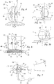
- a remote weapon station 1 is schematically illustrated.
- the remote weapon station 1 is mountable onto a gun boat (not shown) or the like.
- the remote weapon station 1 comprises a weapon support 3 adapted for rotatable motion about a frst transverse axis X1.
- the weapon support 3 supports a weapon attachment device 5 being rotatable about a second elevation axis X2.
- the second elevation axis X2 comprises an U-shaped part 7 for accommodation of a gun 9.
- the gun 9 is mounted onto the weapon attachment device 5, such as a bayonet fitting (not shown) connected to the second elevation axis X2, wherein the gun 9 easily can be disconnected from the weapon attachment device 5.
- the weapon support 3 supports two legs 11 extending from a platform 13 of the weapon support 3, which platform 13 being rotatable about the axis X1. Between the legs 11 and at their upper ends 15 is the U-shaped part 7 mounted. One of the legs 11 accommodates an ammunition belt guide (not shown).
- the remote weapon station 1 comprises a sight unit 17 for observation of the surroundings and for measuring in a detected target, tracking, classifying the type of target, identifying the target etc.
- the sight unit 17 is rotatable about a third transverse axis X3 and about a fourth elevation axis X4.
- the sight unit 17 has at least one electro-optical sensor 19 with associated apertures 21 arranged in the sight unit's 17 spherical hollow body 23.
- the sight unit 17 is mounted between the weapon support 3 (platform or fundament) and the weapon (gun) attachment device 5, whereby is achieved a compact remote weapon station 1 having a sight unit 17 with a totally independent line of sight relatively the bore axis of the gun 9.
- a control unit 25 is arranged remote from the weapon station 1 and is adapted to control a weapon driving means 27 for rotating the gun 9 about the first transverse axis X1 and the second elevation axis X2 and also to control a sight unit driving means 29 for rotation about the third transverse axis X3 and the fourth elevation axis X4.
- FIGS. 2a, 2b, 2c are shown in a plane view the remote weapon station 1 performing a sight unit rotation towards a target/object 31 while pointing the gun 9 in a somewhat opposite direction.
- both the gun 9 and the sight unit 17 are directed in the same direction.
- the sight unit 17 has started it's rotation r for localising the target 31 without pointing the gun 9 at the target 31. In some cases this performance can be beneficial since pointing a gun at an object may result in a non-desirable reaction.
- FIG. 2b is shown how the sight line L will be covered by one of the legs 11 of the weapon support 3.
- This problem is partly solved by using e.g. two sensors or two in pair arranged sensors 19, such as one TV- and one IR-sensor or two in pair arranged TV- and IR-sensors.
- the first sensor or pair of sensors observes the surroundings, the second sensor or pair of sensors instantaneously will lose contact with the target 31 since the sight line L is covered by the leg 11.
- the second sensor or pair of sensors pick up the line of sight to the target L.
- the control unit 25 controls the weapon support 3 to rotate in an opposite direction marked with arrow r2, see FIG. 2c (an overlapping function).
- the legs 11 can be arranged as a system of framework.
- the apertures and sensors can be parked occasionally behind one of the legs 11.
- the sight unit 17 is rotatable about the third transverse axis X3 and about, perpendicular to the third axis X3, the fourth elevation axis X4, independently of the position or rotation of the weapon support 3 about the first transverse axis X1 and the second elevation axis X2.
- a spherical hollow body 23 embodying the sight sensors 19 an independent 360° traverse operation of the sight unit 17 is possible without moving the gun 9, wherein the silhouette of the remote weapon station 1 not being changed, thus minimizing the risk of being detected by the object/target 31 by visual means.
- FIGS. 1 and 2 show a sight unit 17 comprising an spherical hollow body 23 embodying the sensors 19, as an alternative the sight unit 17 may comprise a first essentially cylindrical or cubical, hollow body 23 accommodating at least one electro-optical sensor 19.
- FIGS. 3a, 3b, 3c Such an embodiment is shown in FIGS. 3a, 3b, 3c .
- FIG. 3c shows the sight unit 17 directed to the opposite direction relatively the gun 9 in a horizontal action.
- FIGS. 3a, 3b, 3c The embodiment of FIGS. 3a, 3b, 3c is arranged such that the first transverse axis X1 coincides with the third transverse axis X3 of the sight unit 17, whereby is provided a remote weapon station 1 being capable to utilize a compact motor driving system using the same axis for the transverse rotations as being described below with reference to FIG. 6 .
- a cylindrical hollow body 33 encloses all interior movable parts, such as electro-optical sensors, of the sight unit for protecting said parts.
- the body is transparent and armour cased. In such a way, on one hand the interior equipment is protected from splinters, small arms fire or ricochets etc., and on the other hand hidden from being detected by the object/target.
- the sight unit 17 comprises an essentially spherical body 23 adjacent to one end of a rotationally symmetrical body 35, preferably of circular cylindrical shape.
- the spherical body 23 comprises a circular central section 37 surrounded by two peripheral half sections 39 on each side (only one section 39 is illustrated with broken line).
- Each peripheral half section is provided with two apertures 21.
- the sections each only have one aperture.
- the spherical hollow body 23 is rotatable in relation to the rotationally symmetrical body 35 about the third transverse axis X3.
- the two peripheral half sections 39 are rigidly mechanically interconnected and arranged rotatable so as to be capable of being rotated about the fourth elevation axis X4.
- the elevation can be limited to a range wherein the apertures 21 are in one end position oriented at an angle downwards relative to the horizontal plane and, in the other end position, oriented at an angle upwards relative to the horizontal plane.
- the electro-optical sensors 19 can be selected from a variety of sensors, e.g. TV, IRV, laser rangefinder and laser illuminator.
- the use of the sight unit 17 with a spherical form arranged in the remote weapon station 1 provides independent 360° traverse operation with an optimal configuration of the remote weapon station 1 with regard to overall volume, interior sensor volume utilisation, ballistic protection, signature management, and weapon dumping/elevation angles.
- FIG. 5a and 5b are shown an embodiment of the remote weapon station 1, wherein the weapon support 3 comprises a tiltable leg arrangement 41 supporting the weapon attachment device 5.
- the leg arrangement 41 comprises two legs 11 being tiltable about a tilting point p over the essentially spherical, hollow body 23 being also shown in FIG. 4 .
- the tilting action of the weapon attachment device 5 over the sight unit 17 performs an imaginary circular arc c essentially with the same radius as the radius of the circumference of the essentially spherical, hollow body 23.
- the remote weapon station 1 can be made lower in a transportation mode without the need of making the volume of the sight equipment smaller.
- FIG. 6 is schematically illustrated a compact motor driving system 43 using the same axis X1, X3 for the transverse rotations of both the sensor unit 17 and the weapon support 3.
- the first axis X1 coincides with the third axis X3.
- a first rotor 45 is arranged rotatable about the common transverse axis X1 and X3 and is connected to the legs 11 of the weapon support 3 and via a first bearing 47 connected to the weapon carrier 49, such as a gun boat.
- a first stator 51 actuates the first rotor 45 for transverse rotation of the gun 9.
- a further second bearing 53 is arranged between the first rotor 45 and a second rotor 55 carrying the circular central section 37, within which the electro-optical sensors 19 are rotatable arranged for elevation rotation about the fourth elevation axis X4.
- a second stator 57 actuates the second rotor 55 for the transverse rotation of the circular central section 37 and the peripheral sections (not shown) of the sight unit 17.
- FIG. 7 is shown schematically the aiming of the remote weapon station 1 at a moving target 31.
- the gun's 9 pointing direction and the sight line L of the sight unit 17 is broken for sake of clarity and the target 31 is drawn smaller than the remote weapon station 1 for the sake of illustration.
- An aiming-off angle ⁇ is required as the target 31 is moving.
- the compact remote weapon station's 1 sight unit 17 detecting the target 31 is rotated independently of the gun's 9 motion.
- the control unit 25 is estimated the required aiming-off angle ⁇ , dependent upon the velocity of the target 31 and eventually the velocity of the carrier carrying the remote weapon station 1. Also parameters as wind direction and speed etc. are considered.
- An uniaxial rate gyro is stabilizing the gun 9 via an elevation drive unit 27 and a transverse drive unit arranged at the second elevation axis X2 and the transverse axis, and the electro-optical sensors 19 are stabilized via a sensor unit elevation drive system (not shown) of an elevation drive system and transverse drive system arranged within the circular central section 37 of the sight unit 17.
- the remote weapon station 1 is according to one embodiment of the invention provided with a weapon support 3 being comprised in a motorized gun control system. Thereby is achieved that the remote weapon station 1 is applicable to an available carrier, such as a truck, car, gun boat, tank, helicopter etc.
- the sight unit 17 of the remote weapon station 1 can control at least one separate weapon 60 placed at a distance from the remote weapon station 1.Control is achieved by means of being directly connected to the weapon, illuminating the target for the weapon or providing in-the-air guidance to the weapon or a combination of any of these means.
- the invention is not limited to a specific embodiment herein, but may also consist of several combinations of the presented embodiments.
- only one peripheral half section can provide an aperture and none in the other section.
- the elevation drive system and transverse drive system may be arranged in one of the supports of the sight unit.
- the sight unit's hollow body can have a central section being rotatable and two outer section acting as supports (fork-shaped assembly) or the section being supported by only one peripheral support.
- the sight unit may be placed between the weapon support and the weapon attachment device by mounting the sight unit "hanging" under the weapon attachment device or adjacent the same.
Description
- The present invention relates to a remote weapon station according to the precharacterising part of
claim 1. The present invention relates, but not limited, to industries making remotely controlled weapon stations, machine-guns, automatic grenade launchers, missile firing equipment etc. - Remote weapon stations of the type indicated in the introduction are available on the market today. A three axes remote weapon station comprises a gun being turnable about a first transverse axis and a second elevation axis and a sight unit rotatable about a third elevation axis, wherein the third axis is primary used when firing grenade launcher type weapons. The four axes weapon stations is provided for that the line of sight can be controlled independently of the bore axis of the weapon, wherein the bore axis weapon is stabilised in two axes. However, in such a station according to prior art the freedom of movement of the sight unit is limited, since the sight unit must be moved together with the gun, limiting the usage of the sight and weapon station when the relative speed between the target and the weapon station is high since a high relative speed requires large offset angles between the line of sight and the bore axis of the gun in order to hit the target. Also the use of such prior art systems is limited when the platform on which the weapon station is mounted is performing a roll motion relative to the bore axis of the gun when the gun is directed to hit the target. Furthermore prior art weapon stations with three or four axes all make a change of silhouette when the sight unit and thus the weapon support rotates.
- Known systems having four axes stabilizing arrangements are bulky in width or height. This since the sight unit is placed above or attached onto the side of the weapon support. Prior art systems with the sight unit attached onto the side of the weapon, wherein the concentration of masses asymmetrically will cause the station to be unbalanced, are also difficult to stabilise without the use of undesired counter weights or larger and thus heavier drives. Also prior art systems being three axes stabilizing arrangements, wherein the bore axis of the weapon is stabilised in two axes and the line of sight line of the sight unit is stabilised in one axis, suffer from the disadvantages that an image generating sensor (such as TV, IR etc.) field of vision must be adapted for holding the target within said field of vision, which is extremely difficult when a vehicle comprising the station is moving since the system must be directed towards the target for facilitating the determination of the distance to the target, requiring a long time.
- Prior art systems having four axes arrangement wherein solely the weapon's bore axis is two axes stabilized, involve that the field of vision must be selected such that the target remain within the field of vision when the vehicle is moving (roll/pitch/heading). Also this means that it is difficult to measure the distance to the target when the vehicle moves, especially when angles for super elevation and lead angles are added to compensate for relative motion between the target and the weapon station. Furthermore, prior art systems wherein solely the sight unit's line of sight is two axes stabilized involve that it is difficult to hit the target with fired ammunition.
-
US 5273236 discloses an apparatus provided for designating a plurality of objects within a field of view and thereafter simultaneously tracking each of the objects. A further document,US 4576346 , describes a seeker head for a target seeking missile, which comprises a seeker adapted to be directed to a target. -
EP 111 192 - The object of the present invention is to overcome the drawbacks of known techniques.
- This has been solved by a remote weapon station being defined in the introduction, the remote weapon station is characterised by the features of claim's 1 characterising part. In such a way a not bulky remote weapon station is achieved at the same time as the operator of the remote weapon station is able to perform targeting and surveillance without changing the remote weapon station's silhouette and thus reducing the risk of being detected by visual means. The concentration of masses will also be symmetrically arranged which will make the remote weapon station possible to stabilise without adding extra weight in the form of undesired counter weights or larger drives. Thereby increase the usage of the weapon station when the platform on which the weapon station is mounted is moving. Thereby is also achieved a possibility to utilise the sensor without pointing a gun directly at the object of interest. Also there is a possibility to start searching for a new target while firing the gun at the first acquired target. A positive effect is that a weapon station can be provided with a high precision stabilised system having a sighting function with an unitary installation of a sight unit matching the performance of the weapon and at the same time providing a sufficient performance for e.g. missile guidance. Thereby is also achieved that the sight unit in an effective manner can follow a target by controlling the weapon via a control unit for aiming-off, at the same time as compensation means provides for compensation of eventual uneven motion of the remote weapon station, for example being mounted at a gun boat. This is achieved by that the control unit can control the sight unit independently of the gun aiming by means of the arrangement of the remote weapon station according to the present invention. A compact remote weapon station is thus achieved having a sight unit with a totally independent line of sight relatively the pointing of the gun having the sight unit correctly balanced relatively the weapon and providing an exact line of sight. Thus is also achieved a remote weapon station having a sight unit, which weapon station can be used utilizing the sight unit without the need of other kinds of compensation for lead angles and/or super elevation.
- Thus, the objects of the invention is to provide a compact remote weapon station, wherein the assembly permits that the angle between the bore axis of the weapon and the line of sight of the sight in a controllable manner can be made independently of each other. The weapon's bore axis being stabilized in two axes and the sight unit's line of sight being stabilized in two axes.
- The effects being provided by such an arrangement is for example that the target can be placed in the centre of a image generating display and the distance to the target continuously can be measured by a laser range finder etc, wherein the weapon's bore axis can be directed in such a way that the fired ammunition hits the target with precision. Also is achieved that the bore axis of the weapon and the line of sight of the sight unit can be oriented relative each other in such a way that the sight unit can be used without the need of directing the weapon towards the target.
- Also is achieved the advantage that the sight unit's line of sight can be stabilized and directed with a higher accuracy than being provided by systems only stabilising the weapon's bore axis.
- Preferably, the weapon support is rotatable about the first transverse axis independently of the rotatable motion of the sight unit about the third transverse axis such that the weapon can be directed essentially in another direction relatively the search direction of the sight unit.
- In such a way is achieved that the weapon can be rotated to the opposite direction relatively to the sight unit's target tracking(or search) direction. This is also a beneficial feature for shortening the time when for example a supporting leg of the weapon carriage covers the line of sight, by controlling the weapon support's and sight unit's relative rotation.
- Suitably, the weapon support also is arranged to be controlled to rotate about the first transverse axis dependent upon the rotatable motion of the sight unit about the third transverse axis.
- Thereby is provided an alternative mode for controlling the weapon support to follow the sight unit's rotational movement, at the same time as the weapon support can be disconnected from following the target.
- Suitably, the first axis coincides with the third axis.
- Thereby is provided a remote weapon station being capable to utilize a compact motor driving system using the same axis for the transverse rotations.
- Preferably, the sight unit comprises a first essentially spherical, hollow body which interacts with a second essentially rotationally symmetrical body, both bodies being rotatable in relation to one another about the transverse axis, the spherical body accommodating at least one electro-optical sensor, being rotatable about the fourth elevation axis.
- Thus is also achieved that the sight unit can be independently stabilised, thereby making the remote weapon station optimized for high precision sensor systems, e.g. laser illumination at long ranges. The use of a sensor sight system with a spherical form arranged in the remote weapon station provides independent 360° traverse operation with an optimal configuration of the remote weapon station with regard to overall volume, interior sensor volume utilisation, ballistic protection, signature management, and weapon dumping/elevation angles.
- Alternatively, the weapon support comprises a tiltable leg arrangement supporting the weapon attachment device, the leg arrangement being tiltable over the first essentially spherical, hollow body.
- In such a way the remote weapon station can be made lower for transportation purposes by tilting the weapon attachment device over the sight unit. The tilting action performing an imaginary circular arc essentially with the same radius as the radius of the first essentially spherical, hollow body.
- Preferably, the sight unit comprises a first essentially cylindrical, hollow body accommodating at least one electro-optical sensor.
- Thereby is achieved a large volume for sight equipment even still performing an optimal signature management, that is having essentially the same silhouette independently the sensor transverse motion about the third axis.
- Alternatively, the hollow body encloses all interior movable parts, such as electro-optical sensors, of the sight unit for hiding said parts. The body is preferably armour cased and transparent and/or partly transparent.
- In such a way, on one hand the interior equipment is protected from splinters, small arms fire or ricochets etc., and on the other hand hidden from being detected by the object/target.
- Alternatively, the weapon support being comprised in a motorized gun control system.
- Thereby is achieved that the remote weapon station is applicable to an available platform, such as a truck, an armoured car, gun boat, tank, helicopter etc.
- Suitably, the sight unit is arranged for controlling at least one weapon disposed at a distance from the remote weapon station.
- The present invention will now be described by way of example with reference to the accompanying schematic drawings of which:
-
FIG. 1a schematically illustrates a remote weapon station in a front view, -
FIG. 1b schematically illustrates the station inFIG. 1a in a side view, -
FIG. 1c schematically illustrates the station inFIG. 1a in a plane view, -
FIGS 2a-2c schematically illustrate the station inFIG. 1c in motion, -
FIGS. 3a-3c schematically illustrate a remote weapon station according to a second embodiment, -
FIGS 3d-3f schematically illustrate a remote weapon station according to a further embodiment, -
FIG. 4 schematically illustrates parts of a sight unit shown inFIGs 1a-2c , -
FIGS. 5a-5b schematically illustrate a leg arrangement of a remote weapon station, -
FIG. 6 schematically illustrates a motor driving system of the remote weapon station inFIG. 4 , and -
FIG. 7 schematically illustrates the aiming of the remote weapon station at a moving target. - Hereinafter, embodiments of the present invention will be described in detail with reference to the accompanying drawings related to the embodiments, wherein for the sake of clarity and understanding of the invention some details of no importance are deleted from the drawings.
- Referring to
FIGS. 1a, 1b, 1c , aremote weapon station 1 is schematically illustrated. Theremote weapon station 1 is mountable onto a gun boat (not shown) or the like. Theremote weapon station 1 comprises aweapon support 3 adapted for rotatable motion about a frst transverse axis X1. - The
weapon support 3 supports aweapon attachment device 5 being rotatable about a second elevation axis X2. The second elevation axis X2 comprises an U-shaped part 7 for accommodation of agun 9. Thegun 9 is mounted onto theweapon attachment device 5, such as a bayonet fitting (not shown) connected to the second elevation axis X2, wherein thegun 9 easily can be disconnected from theweapon attachment device 5. - The
weapon support 3 supports twolegs 11 extending from aplatform 13 of theweapon support 3, whichplatform 13 being rotatable about the axis X1. Between thelegs 11 and at their upper ends 15 is the U-shaped part 7 mounted. One of thelegs 11 accommodates an ammunition belt guide (not shown). - The
remote weapon station 1 comprises asight unit 17 for observation of the surroundings and for measuring in a detected target, tracking, classifying the type of target, identifying the target etc. Thesight unit 17 is rotatable about a third transverse axis X3 and about a fourth elevation axis X4. Thesight unit 17 has at least one electro-optical sensor 19 with associatedapertures 21 arranged in the sight unit's 17 sphericalhollow body 23. Thesight unit 17 is mounted between the weapon support 3 (platform or fundament) and the weapon (gun)attachment device 5, whereby is achieved a compactremote weapon station 1 having asight unit 17 with a totally independent line of sight relatively the bore axis of thegun 9. It also means that thesight unit 17 can be correctly stabilized/directed relatively thegun 9 and providing an exact line of sight. Since thegun 9 is dispensed in a vertical plane comprising the first transverse axis X1 and essentially the third transverse axis X3, an optimal aiming can be achieved. Acontrol unit 25 is arranged remote from theweapon station 1 and is adapted to control a weapon driving means 27 for rotating thegun 9 about the first transverse axis X1 and the second elevation axis X2 and also to control a sight unit driving means 29 for rotation about the third transverse axis X3 and the fourth elevation axis X4. By arranging thesight unit 17 between the weapon support 3 (fundament or platform) and the weapon (gun 9) cables and wires can be hidden and protected and easy to mount during the manufactory of the station. - In
FIGS. 2a, 2b, 2c are shown in a plane view theremote weapon station 1 performing a sight unit rotation towards a target/object 31 while pointing thegun 9 in a somewhat opposite direction. InFIG. 2a both thegun 9 and thesight unit 17 are directed in the same direction. InFIG. 2b thesight unit 17 has started it's rotation r for localising thetarget 31 without pointing thegun 9 at thetarget 31. In some cases this performance can be beneficial since pointing a gun at an object may result in a non-desirable reaction. - Meanwhile the
sight unit 17 rotates, the sight unit's 17sensors 19 perform a scanning of the surroundings. InFIG. 2b is shown how the sight line L will be covered by one of thelegs 11 of theweapon support 3. This problem is partly solved by using e.g. two sensors or two in pair arrangedsensors 19, such as one TV- and one IR-sensor or two in pair arranged TV- and IR-sensors. Meanwhile the first sensor or pair of sensors observes the surroundings, the second sensor or pair of sensors instantaneously will lose contact with thetarget 31 since the sight line L is covered by theleg 11. When the first sensor or pair of sensors has lost contact with thetarget 31, the second sensor or pair of sensors pick up the line of sight to the target L. For even more shortening the time, when theleg 11 covers thesensors 19, the control unit 25 (seeFIG. 1a ) controls theweapon support 3 to rotate in an opposite direction marked with arrow r2, seeFIG. 2c (an overlapping function). For even better visibility of thesensors 19, thelegs 11 can be arranged as a system of framework. For protection of the sensors the apertures and sensors can be parked occasionally behind one of thelegs 11. - The
sight unit 17 is rotatable about the third transverse axis X3 and about, perpendicular to the third axis X3, the fourth elevation axis X4, independently of the position or rotation of theweapon support 3 about the first transverse axis X1 and the second elevation axis X2. By using a sphericalhollow body 23 embodying thesight sensors 19, an independent 360° traverse operation of thesight unit 17 is possible without moving thegun 9, wherein the silhouette of theremote weapon station 1 not being changed, thus minimizing the risk of being detected by the object/target 31 by visual means. - Whereas the
FIGS. 1 and 2 show asight unit 17 comprising an sphericalhollow body 23 embodying thesensors 19, as an alternative thesight unit 17 may comprise a first essentially cylindrical or cubical,hollow body 23 accommodating at least one electro-optical sensor 19. Such an embodiment is shown inFIGS. 3a, 3b, 3c . Thereby is achieved a large volume for sight equipment even still performing an optimal signature management, that is having essentially the same silhouette independently of the sensor transverse motion about the third axis X3. TheFIG. 3c shows thesight unit 17 directed to the opposite direction relatively thegun 9 in a horizontal action. - The embodiment of
FIGS. 3a, 3b, 3c is arranged such that the first transverse axis X1 coincides with the third transverse axis X3 of thesight unit 17, whereby is provided aremote weapon station 1 being capable to utilize a compact motor driving system using the same axis for the transverse rotations as being described below with reference toFIG. 6 . - A cylindrical
hollow body 33 encloses all interior movable parts, such as electro-optical sensors, of the sight unit for protecting said parts. The body is transparent and armour cased. In such a way, on one hand the interior equipment is protected from splinters, small arms fire or ricochets etc., and on the other hand hidden from being detected by the object/target. - In
FIG. 4 is shown thesight unit 17 inFIGS. 1a, 1b, 1c more in detail. Thesight unit 17 comprises an essentiallyspherical body 23 adjacent to one end of a rotationallysymmetrical body 35, preferably of circular cylindrical shape. Thespherical body 23 comprises a circularcentral section 37 surrounded by twoperipheral half sections 39 on each side (only onesection 39 is illustrated with broken line). Each peripheral half section is provided with twoapertures 21. Of course can according to other embodiments the sections each only have one aperture. - The spherical
hollow body 23 is rotatable in relation to the rotationallysymmetrical body 35 about the third transverse axis X3. By the rotation about the third transverse axis X3 it is possible to bring about 360° rotation. The twoperipheral half sections 39 are rigidly mechanically interconnected and arranged rotatable so as to be capable of being rotated about the fourth elevation axis X4. The elevation can be limited to a range wherein theapertures 21 are in one end position oriented at an angle downwards relative to the horizontal plane and, in the other end position, oriented at an angle upwards relative to the horizontal plane. - The electro-
optical sensors 19 can be selected from a variety of sensors, e.g. TV, IRV, laser rangefinder and laser illuminator. - The use of the
sight unit 17 with a spherical form arranged in theremote weapon station 1 provides independent 360° traverse operation with an optimal configuration of theremote weapon station 1 with regard to overall volume, interior sensor volume utilisation, ballistic protection, signature management, and weapon dumping/elevation angles. - In
FIG. 5a and 5b are shown an embodiment of theremote weapon station 1, wherein theweapon support 3 comprises atiltable leg arrangement 41 supporting theweapon attachment device 5. Theleg arrangement 41 comprises twolegs 11 being tiltable about a tilting point p over the essentially spherical,hollow body 23 being also shown inFIG. 4 . In such a way theremote weapon station 1 can be made lower for transportation purposes by tilting theweapon attachment device 5 over thesight unit 17. The tilting action of theweapon attachment device 5 over thesight unit 17 performs an imaginary circular arc c essentially with the same radius as the radius of the circumference of the essentially spherical,hollow body 23. Thereby is achieved that theremote weapon station 1 can be made lower in a transportation mode without the need of making the volume of the sight equipment smaller. - In
FIG. 6 is schematically illustrated a compactmotor driving system 43 using the same axis X1, X3 for the transverse rotations of both thesensor unit 17 and theweapon support 3. The first axis X1 coincides with the third axis X3. Afirst rotor 45 is arranged rotatable about the common transverse axis X1 and X3 and is connected to thelegs 11 of theweapon support 3 and via afirst bearing 47 connected to theweapon carrier 49, such as a gun boat. - A
first stator 51 actuates thefirst rotor 45 for transverse rotation of thegun 9. A furthersecond bearing 53 is arranged between thefirst rotor 45 and asecond rotor 55 carrying the circularcentral section 37, within which the electro-optical sensors 19 are rotatable arranged for elevation rotation about the fourth elevation axis X4. Asecond stator 57 actuates thesecond rotor 55 for the transverse rotation of the circularcentral section 37 and the peripheral sections (not shown) of thesight unit 17. - In
FIG. 7 is shown schematically the aiming of theremote weapon station 1 at a movingtarget 31. The gun's 9 pointing direction and the sight line L of thesight unit 17 is broken for sake of clarity and thetarget 31 is drawn smaller than theremote weapon station 1 for the sake of illustration. An aiming-off angle α is required as thetarget 31 is moving. The compact remote weapon station's 1sight unit 17 detecting thetarget 31 is rotated independently of the gun's 9 motion. By means of thecontrol unit 25 is estimated the required aiming-off angle α, dependent upon the velocity of thetarget 31 and eventually the velocity of the carrier carrying theremote weapon station 1. Also parameters as wind direction and speed etc. are considered. An uniaxial rate gyro is stabilizing thegun 9 via anelevation drive unit 27 and a transverse drive unit arranged at the second elevation axis X2 and the transverse axis, and the electro-optical sensors 19 are stabilized via a sensor unit elevation drive system (not shown) of an elevation drive system and transverse drive system arranged within the circularcentral section 37 of thesight unit 17. - The
remote weapon station 1 is according to one embodiment of the invention provided with aweapon support 3 being comprised in a motorized gun control system. Thereby is achieved that theremote weapon station 1 is applicable to an available carrier, such as a truck, car, gun boat, tank, helicopter etc. - The
sight unit 17 of theremote weapon station 1 can control at least oneseparate weapon 60 placed at a distance from the remote weapon station 1.Control is achieved by means of being directly connected to the weapon, illuminating the target for the weapon or providing in-the-air guidance to the weapon or a combination of any of these means. - The invention is not limited to a specific embodiment herein, but may also consist of several combinations of the presented embodiments. For example, only one peripheral half section can provide an aperture and none in the other section. Alternatively, the elevation drive system and transverse drive system may be arranged in one of the supports of the sight unit. For example, the sight unit's hollow body can have a central section being rotatable and two outer section acting as supports (fork-shaped assembly) or the section being supported by only one peripheral support. Of course, the sight unit may be placed between the weapon support and the weapon attachment device by mounting the sight unit "hanging" under the weapon attachment device or adjacent the same.
Claims (10)
- A remote weapon station comprising a weapon support (3) adapted for rotatable motion about a first transverse axis (X1), the weapon support (3) including a platform (13) supporting a weapon attachment device (5) supporting a weapon (9), said weapon attachment device being rotatable about a second elevation axis (X2) perpendicular to the first transverse axis (X1), the remote weapon station (1) further comprising a sight unit (17) rotatable about a third transverse axis (X3) and about a fourth elevation axis (X4), perpendicular to the third transverse axis,
characterized in that
said sight unit (17) is rotatable about said third transverse axis (X3) and said fourth elevation axis (X4) independently of the position or rotation of the weapon support (3) about the first transverse axis (X1) and of the weapon attachment device (5) about the second elevation axis (X2),
and in that the sight unit (17) is mounted to the platform and arranged between the platform (13) of the weapon support (3) and the weapon (9) attached to the weapon attachment device (5) and in that the weapon's bore axis is stabilized in two axes and the sight unit's line of sight is stabilized in two axes. - The remote weapon station according to claim 1, wherein the weapon support (3) is rotatable about the first transverse axis (X1) independently of the rotatable motion of the sight unit (17) about the third transverse axis (X3) such that the weapon (9) can be directed in essentially another direction relatively the line of sight of the sight unit (17).
- The remote weapon station according to any of claims 1 or 2, wherein the weapon support (3) also is arranged to be controlled to rotate about the first transverse axis (X1) dependent upon the rotatable motion of the sight unit (17) about the third transverse axis (X3).
- The remote weapon station according to any of the preceding claims, wherein the first axis (X1) coincides with the third axis (X3).
- The remote weapon station according to any of the preceding claims, wherein the sight unit (17) comprises a first essentially spherical, hollow body (23) which interacts with a second essentially rotationally symmetrical body (35), both bodies being rotatable in relation to one another relative to the third transverse axis (X3), the spherical body (23) accommodating at least one electro-optical sensor (19), the sensor (19) being rotatable about the fourth elevation axis (X4).
- The remote weapon station according to claim 5, wherein the weapon support (3) comprises a tiltable leg arrangement (41) supporting the weapon attachment device (5), the leg arrangement (41) being tiltable over the first essentially spherical, hollow body (23).
- The remote weapon station according to any of claims 1-4, wherein the sight unit (17) comprises a first essentially cylindrical, hollow body (33) accommodating at least one electro-optical sensor (19).
- The remote weapon station according to any of the preceding claims, wherein an essentially transparent hollow body (23, 33) encloses all interior movable parts, such as electro-optical sensors, of the sight unit (17) for protecting and hiding said parts.
- The remote weapon station according to any of the preceding claims, wherein the weapon support (3) being comprised in a gun control system.
- The remote weapon station according to any of the preceding claims, wherein the sight unit (17) is adapted for controlling or guiding at least one weapon (60) disposed at a distance from the remote weapon station (1).
Priority Applications (2)
| Application Number | Priority Date | Filing Date | Title |
|---|---|---|---|
| EP06124200.4A EP1923657B1 (en) | 2006-11-16 | 2006-11-16 | A compact, fully stabilised, four axes, remote weapon station with independent line of sight |
| US11/984,397 US20080148931A1 (en) | 2006-11-16 | 2007-11-16 | Compact, fully stablised, four axes, remote weapon station with independent line of sight |
Applications Claiming Priority (1)
| Application Number | Priority Date | Filing Date | Title |
|---|---|---|---|
| EP06124200.4A EP1923657B1 (en) | 2006-11-16 | 2006-11-16 | A compact, fully stabilised, four axes, remote weapon station with independent line of sight |
Publications (2)
| Publication Number | Publication Date |
|---|---|
| EP1923657A1 EP1923657A1 (en) | 2008-05-21 |
| EP1923657B1 true EP1923657B1 (en) | 2017-05-03 |
Family
ID=37897300
Family Applications (1)
| Application Number | Title | Priority Date | Filing Date |
|---|---|---|---|
| EP06124200.4A Revoked EP1923657B1 (en) | 2006-11-16 | 2006-11-16 | A compact, fully stabilised, four axes, remote weapon station with independent line of sight |
Country Status (2)
| Country | Link |
|---|---|
| US (1) | US20080148931A1 (en) |
| EP (1) | EP1923657B1 (en) |
Cited By (1)
| Publication number | Priority date | Publication date | Assignee | Title |
|---|---|---|---|---|
| WO2024003808A1 (en) * | 2022-07-01 | 2024-01-04 | Leonardo S.P.A. | Turret, in particular for naval applications, provided with a device for moving an ammunition guidance system |
Families Citing this family (18)
| Publication number | Priority date | Publication date | Assignee | Title |
|---|---|---|---|---|
| US7966763B1 (en) | 2008-05-22 | 2011-06-28 | The United States Of America As Represented By The Secretary Of The Navy | Targeting system for a projectile launcher |
| US8336442B2 (en) * | 2008-11-21 | 2012-12-25 | The United States Of America As Represented By The Secretary Of The Army | Automatically-reloadable, remotely-operated weapon system having an externally-powered firearm |
| US8646374B2 (en) * | 2010-07-27 | 2014-02-11 | Raytheon Company | Weapon station and associated method |
| US8620023B1 (en) * | 2010-09-13 | 2013-12-31 | The Boeing Company | Object detection and location system |
| US8787114B1 (en) | 2010-09-13 | 2014-07-22 | The Boeing Company | Audio surveillance system |
| US9243869B1 (en) | 2011-08-09 | 2016-01-26 | Raytheon Company | Weapon posturing system and methods of use |
| DE102012102235C5 (en) | 2012-03-16 | 2017-10-26 | Krauss-Maffei Wegmann Gmbh & Co. Kg | Military vehicle and method of aligning a piece of equipment |
| DE102013101635A1 (en) | 2013-02-19 | 2014-08-21 | Krauss-Maffei Wegmann Gmbh & Co. Kg | weapon station |
| FR3019279B1 (en) * | 2014-03-28 | 2018-06-22 | Safran Electronics & Defense | OPTRONIC ARMY TURTLE |
| US9464856B2 (en) | 2014-07-22 | 2016-10-11 | Moog Inc. | Configurable remote weapon station having under armor reload |
| US9568267B2 (en) | 2014-07-22 | 2017-02-14 | Moog Inc. | Configurable weapon station having under armor reload |
| RU167543U1 (en) * | 2015-08-25 | 2017-01-10 | Открытое Акционерное Общество "Пеленг" | Implement tracking device |
| DE102015119847A1 (en) | 2015-09-18 | 2017-03-23 | Rheinmetall Defence Electronics Gmbh | Remote weapon station and method of operating a remote weapon station |
| WO2021080684A1 (en) | 2019-10-25 | 2021-04-29 | Aimlock Inc. | Remotely operable weapon mount |
| US11499791B2 (en) | 2019-10-25 | 2022-11-15 | Aimlock Inc. | Trigger and safety actuating device and method therefor |
| US11835312B1 (en) | 2021-01-22 | 2023-12-05 | The United States Of America As Represented By The Secretary Of The Army | Combat optimized ballistic remote armament |
| FR3128523B1 (en) * | 2021-10-26 | 2023-10-27 | Arquus | Aiming and defense system comprising a cupola and a laser system and motor vehicle comprising such an aiming and defense system |
| FR3132140B1 (en) * | 2022-01-21 | 2024-04-05 | Compagnie Ind Des Lasers Cilas | Laser weapon carried by a pod |
Family Cites Families (12)
| Publication number | Priority date | Publication date | Assignee | Title |
|---|---|---|---|---|
| FR2484626A1 (en) * | 1980-06-11 | 1981-12-18 | Applic Mach Motrices | Anti-aircraft target tracking system for tank - employs TV cameras and servo loops with weapon firing correction for weapon turret positioning |
| NL8204706A (en) | 1982-12-06 | 1984-07-02 | Hollandse Signaalapparaten Bv | INTEGRATED WEAPON FIRE CONTROL SYSTEM. |
| DE3317232A1 (en) | 1983-05-11 | 1984-11-15 | Bodenseewerk Gerätetechnik GmbH, 7770 Überlingen | SEARCH HEAD FOR TARGET-SEARCHING AIRBODIES |
| US5197691A (en) * | 1983-09-16 | 1993-03-30 | Martin Marietta Corporation | Boresight module |
| DE3912672A1 (en) * | 1989-04-18 | 1990-10-25 | Rheinmetall Gmbh | DISTANCE MINE WITH OPTICAL SEEKER |
| US5273236A (en) | 1992-12-02 | 1993-12-28 | Electronics & Space Corp. | Multiple designation missile system |
| DE19752464A1 (en) * | 1997-11-27 | 1999-07-15 | Dynamit Nobel Ag | Automatic adaptive weapon to combat vehicles |
| CA2245406C (en) * | 1998-08-24 | 2006-12-05 | James Hugh Lougheed | Aiming system for weapon capable of superelevation |
| AUPR080400A0 (en) * | 2000-10-17 | 2001-01-11 | Electro Optic Systems Pty Limited | Autonomous weapon system |
| SE519151E5 (en) * | 2001-11-19 | 2013-07-30 | Bae Systems Bofors Ab | Weapon sight with sight sensors intended for vehicles, vessels or equivalent |
| US6896423B2 (en) * | 2002-09-20 | 2005-05-24 | Pelco | Camera mounting enclosure and method of installation |
| US20080034954A1 (en) * | 2005-01-31 | 2008-02-14 | David Ehrlich Grober | Stabilizing mount for hands-on and remote operation of cameras, sensors, computer intelligent devices and weapons |
-
2006
- 2006-11-16 EP EP06124200.4A patent/EP1923657B1/en not_active Revoked
-
2007
- 2007-11-16 US US11/984,397 patent/US20080148931A1/en not_active Abandoned
Non-Patent Citations (1)
| Title |
|---|
| "PERI-R12", TDV 1240/050-40 (F), GERATEBESCHREIBUNG, pages C1 - C15 |
Cited By (1)
| Publication number | Priority date | Publication date | Assignee | Title |
|---|---|---|---|---|
| WO2024003808A1 (en) * | 2022-07-01 | 2024-01-04 | Leonardo S.P.A. | Turret, in particular for naval applications, provided with a device for moving an ammunition guidance system |
Also Published As
| Publication number | Publication date |
|---|---|
| EP1923657A1 (en) | 2008-05-21 |
| US20080148931A1 (en) | 2008-06-26 |
Similar Documents
| Publication | Publication Date | Title |
|---|---|---|
| EP1923657B1 (en) | A compact, fully stabilised, four axes, remote weapon station with independent line of sight | |
| US9523548B2 (en) | Operational control logic for harmonized turret with gimbaled sub-systems | |
| CA2569940C (en) | Improved device for the remote control of a fire arm | |
| EP2478323B1 (en) | Multi-weapons system | |
| KR101081214B1 (en) | Multi Purpose Remote Weapon System | |
| US9121667B1 (en) | Mortar | |
| US4885977A (en) | Stabilized line-of-sight aiming system for use with fire control systems | |
| KR101408340B1 (en) | Remote shooting system | |
| US20080053300A1 (en) | Gun Mount | |
| RU180932U1 (en) | Fighting compartment of an armored personnel carrier with external cannon-machine gun weapons | |
| RU142907U1 (en) | ARMOR TRANSPORT DIVISION | |
| RU2531421C1 (en) | Universal combat module | |
| KR20100096518A (en) | Remote shooting system | |
| CN110108161B (en) | Missile launching device | |
| JPH0755395A (en) | Silencer of gun barrel arms | |
| ES2703898T3 (en) | Look for use with super-lift weapon | |
| RU2612750C1 (en) | Antitank missle complex | |
| RU2816418C1 (en) | Tank weapon system | |
| RU2003107942A (en) | BATTLE DIVISION OF THE ARMORED MACHINE | |
| RU2231737C1 (en) | Tank with antiaircraft armament | |
| RU2256582C1 (en) | Shipboard launcher | |
| RU2222759C2 (en) | Rocket launcher | |
| TR2021018482A2 (en) | AUTOMATIC FIRING SYSTEM WITH GIMBALL | |
| RU2183810C1 (en) | Enclosure of fire structure | |
| TR201906011A1 (en) | AUTOMATIC SHOOTING STABILIZATION SYSTEM |
Legal Events
| Date | Code | Title | Description |
|---|---|---|---|
| PUAI | Public reference made under article 153(3) epc to a published international application that has entered the european phase |
Free format text: ORIGINAL CODE: 0009012 |
|
| AK | Designated contracting states |
Kind code of ref document: A1 Designated state(s): AT BE BG CH CY CZ DE DK EE ES FI FR GB GR HU IE IS IT LI LT LU LV MC NL PL PT RO SE SI SK TR |
|
| AX | Request for extension of the european patent |
Extension state: AL BA HR MK RS |
|
| 17P | Request for examination filed |
Effective date: 20081008 |
|
| 17Q | First examination report despatched |
Effective date: 20081113 |
|
| AKX | Designation fees paid |
Designated state(s): AT BE BG CH CY CZ DE DK EE ES FI FR GB GR HU IE IS IT LI LT LU LV MC NL PL PT RO SE SI SK TR |
|
| GRAP | Despatch of communication of intention to grant a patent |
Free format text: ORIGINAL CODE: EPIDOSNIGR1 |
|
| TPAC | Observations filed by third parties |
Free format text: ORIGINAL CODE: EPIDOSNTIPA |
|
| INTG | Intention to grant announced |
Effective date: 20161026 |
|
| GRAJ | Information related to disapproval of communication of intention to grant by the applicant or resumption of examination proceedings by the epo deleted |
Free format text: ORIGINAL CODE: EPIDOSDIGR1 |
|
| STAA | Information on the status of an ep patent application or granted ep patent |
Free format text: STATUS: GRANT OF PATENT IS INTENDED |
|
| GRAP | Despatch of communication of intention to grant a patent |
Free format text: ORIGINAL CODE: EPIDOSNIGR1 |
|
| INTG | Intention to grant announced |
Effective date: 20161207 |
|
| GRAS | Grant fee paid |
Free format text: ORIGINAL CODE: EPIDOSNIGR3 |
|
| GRAA | (expected) grant |
Free format text: ORIGINAL CODE: 0009210 |
|
| STAA | Information on the status of an ep patent application or granted ep patent |
Free format text: STATUS: THE PATENT HAS BEEN GRANTED |
|
| AK | Designated contracting states |
Kind code of ref document: B1 Designated state(s): AT BE BG CH CY CZ DE DK EE ES FI FR GB GR HU IE IS IT LI LT LU LV MC NL PL PT RO SE SI SK TR |
|
| REG | Reference to a national code |
Ref country code: GB Ref legal event code: FG4D |
|
| REG | Reference to a national code |
Ref country code: AT Ref legal event code: REF Ref document number: 890453 Country of ref document: AT Kind code of ref document: T Effective date: 20170515 Ref country code: CH Ref legal event code: EP |
|
| REG | Reference to a national code |
Ref country code: IE Ref legal event code: FG4D |
|
| REG | Reference to a national code |
Ref country code: DE Ref legal event code: R096 Ref document number: 602006052416 Country of ref document: DE |
|
| REG | Reference to a national code |
Ref country code: NL Ref legal event code: MP Effective date: 20170503 |
|
| REG | Reference to a national code |
Ref country code: AT Ref legal event code: MK05 Ref document number: 890453 Country of ref document: AT Kind code of ref document: T Effective date: 20170503 |
|
| REG | Reference to a national code |
Ref country code: LT Ref legal event code: MG4D |
|
| PG25 | Lapsed in a contracting state [announced via postgrant information from national office to epo] |
Ref country code: GR Free format text: LAPSE BECAUSE OF FAILURE TO SUBMIT A TRANSLATION OF THE DESCRIPTION OR TO PAY THE FEE WITHIN THE PRESCRIBED TIME-LIMIT Effective date: 20170804 Ref country code: FI Free format text: LAPSE BECAUSE OF FAILURE TO SUBMIT A TRANSLATION OF THE DESCRIPTION OR TO PAY THE FEE WITHIN THE PRESCRIBED TIME-LIMIT Effective date: 20170503 Ref country code: LT Free format text: LAPSE BECAUSE OF FAILURE TO SUBMIT A TRANSLATION OF THE DESCRIPTION OR TO PAY THE FEE WITHIN THE PRESCRIBED TIME-LIMIT Effective date: 20170503 Ref country code: ES Free format text: LAPSE BECAUSE OF FAILURE TO SUBMIT A TRANSLATION OF THE DESCRIPTION OR TO PAY THE FEE WITHIN THE PRESCRIBED TIME-LIMIT Effective date: 20170503 Ref country code: AT Free format text: LAPSE BECAUSE OF FAILURE TO SUBMIT A TRANSLATION OF THE DESCRIPTION OR TO PAY THE FEE WITHIN THE PRESCRIBED TIME-LIMIT Effective date: 20170503 |
|
| REG | Reference to a national code |
Ref country code: DE Ref legal event code: R026 Ref document number: 602006052416 Country of ref document: DE |
|
| PLBI | Opposition filed |
Free format text: ORIGINAL CODE: 0009260 |
|
| PG25 | Lapsed in a contracting state [announced via postgrant information from national office to epo] |
Ref country code: LV Free format text: LAPSE BECAUSE OF FAILURE TO SUBMIT A TRANSLATION OF THE DESCRIPTION OR TO PAY THE FEE WITHIN THE PRESCRIBED TIME-LIMIT Effective date: 20170503 Ref country code: PL Free format text: LAPSE BECAUSE OF FAILURE TO SUBMIT A TRANSLATION OF THE DESCRIPTION OR TO PAY THE FEE WITHIN THE PRESCRIBED TIME-LIMIT Effective date: 20170503 Ref country code: IS Free format text: LAPSE BECAUSE OF FAILURE TO SUBMIT A TRANSLATION OF THE DESCRIPTION OR TO PAY THE FEE WITHIN THE PRESCRIBED TIME-LIMIT Effective date: 20170903 Ref country code: SE Free format text: LAPSE BECAUSE OF FAILURE TO SUBMIT A TRANSLATION OF THE DESCRIPTION OR TO PAY THE FEE WITHIN THE PRESCRIBED TIME-LIMIT Effective date: 20170503 Ref country code: NL Free format text: LAPSE BECAUSE OF FAILURE TO SUBMIT A TRANSLATION OF THE DESCRIPTION OR TO PAY THE FEE WITHIN THE PRESCRIBED TIME-LIMIT Effective date: 20170503 Ref country code: BG Free format text: LAPSE BECAUSE OF FAILURE TO SUBMIT A TRANSLATION OF THE DESCRIPTION OR TO PAY THE FEE WITHIN THE PRESCRIBED TIME-LIMIT Effective date: 20170803 |
|
| 26 | Opposition filed |
Opponent name: BAAINBW Effective date: 20171109 |
|
| PLAZ | Examination of admissibility of opposition: despatch of communication + time limit |
Free format text: ORIGINAL CODE: EPIDOSNOPE2 |
|
| PLBA | Examination of admissibility of opposition: reply received |
Free format text: ORIGINAL CODE: EPIDOSNOPE4 |
|
| PG25 | Lapsed in a contracting state [announced via postgrant information from national office to epo] |
Ref country code: EE Free format text: LAPSE BECAUSE OF FAILURE TO SUBMIT A TRANSLATION OF THE DESCRIPTION OR TO PAY THE FEE WITHIN THE PRESCRIBED TIME-LIMIT Effective date: 20170503 Ref country code: SK Free format text: LAPSE BECAUSE OF FAILURE TO SUBMIT A TRANSLATION OF THE DESCRIPTION OR TO PAY THE FEE WITHIN THE PRESCRIBED TIME-LIMIT Effective date: 20170503 Ref country code: CZ Free format text: LAPSE BECAUSE OF FAILURE TO SUBMIT A TRANSLATION OF THE DESCRIPTION OR TO PAY THE FEE WITHIN THE PRESCRIBED TIME-LIMIT Effective date: 20170503 Ref country code: DK Free format text: LAPSE BECAUSE OF FAILURE TO SUBMIT A TRANSLATION OF THE DESCRIPTION OR TO PAY THE FEE WITHIN THE PRESCRIBED TIME-LIMIT Effective date: 20170503 Ref country code: RO Free format text: LAPSE BECAUSE OF FAILURE TO SUBMIT A TRANSLATION OF THE DESCRIPTION OR TO PAY THE FEE WITHIN THE PRESCRIBED TIME-LIMIT Effective date: 20170503 |
|
| PLAN | Information deleted related to communication of a notice of opposition and request to file observations + time limit |
Free format text: ORIGINAL CODE: EPIDOSDOBS2 |
|
| PLAX | Notice of opposition and request to file observation + time limit sent |
Free format text: ORIGINAL CODE: EPIDOSNOBS2 |
|
| PLAR | Examination of admissibility of opposition: information related to receipt of reply deleted |
Free format text: ORIGINAL CODE: EPIDOSDOPE4 |
|
| PG25 | Lapsed in a contracting state [announced via postgrant information from national office to epo] |
Ref country code: IT Free format text: LAPSE BECAUSE OF FAILURE TO SUBMIT A TRANSLATION OF THE DESCRIPTION OR TO PAY THE FEE WITHIN THE PRESCRIBED TIME-LIMIT Effective date: 20170503 |
|
| PLBA | Examination of admissibility of opposition: reply received |
Free format text: ORIGINAL CODE: EPIDOSNOPE4 |
|
| PLAX | Notice of opposition and request to file observation + time limit sent |
Free format text: ORIGINAL CODE: EPIDOSNOBS2 |
|
| PG25 | Lapsed in a contracting state [announced via postgrant information from national office to epo] |
Ref country code: SI Free format text: LAPSE BECAUSE OF FAILURE TO SUBMIT A TRANSLATION OF THE DESCRIPTION OR TO PAY THE FEE WITHIN THE PRESCRIBED TIME-LIMIT Effective date: 20170503 |
|
| REG | Reference to a national code |
Ref country code: DE Ref legal event code: R119 Ref document number: 602006052416 Country of ref document: DE |
|
| PG25 | Lapsed in a contracting state [announced via postgrant information from national office to epo] |
Ref country code: MC Free format text: LAPSE BECAUSE OF FAILURE TO SUBMIT A TRANSLATION OF THE DESCRIPTION OR TO PAY THE FEE WITHIN THE PRESCRIBED TIME-LIMIT Effective date: 20170503 |
|
| GBPC | Gb: european patent ceased through non-payment of renewal fee |
Effective date: 20171116 |
|
| PG25 | Lapsed in a contracting state [announced via postgrant information from national office to epo] |
Ref country code: CH Free format text: LAPSE BECAUSE OF NON-PAYMENT OF DUE FEES Effective date: 20171130 Ref country code: LI Free format text: LAPSE BECAUSE OF NON-PAYMENT OF DUE FEES Effective date: 20171130 |
|
| PG25 | Lapsed in a contracting state [announced via postgrant information from national office to epo] |
Ref country code: LU Free format text: LAPSE BECAUSE OF NON-PAYMENT OF DUE FEES Effective date: 20171116 |
|
| REG | Reference to a national code |
Ref country code: FR Ref legal event code: ST Effective date: 20180731 Ref country code: BE Ref legal event code: MM Effective date: 20171130 |
|
| REG | Reference to a national code |
Ref country code: IE Ref legal event code: MM4A |
|
| PG25 | Lapsed in a contracting state [announced via postgrant information from national office to epo] |
Ref country code: IE Free format text: LAPSE BECAUSE OF NON-PAYMENT OF DUE FEES Effective date: 20171116 Ref country code: FR Free format text: LAPSE BECAUSE OF NON-PAYMENT OF DUE FEES Effective date: 20171130 Ref country code: DE Free format text: LAPSE BECAUSE OF NON-PAYMENT OF DUE FEES Effective date: 20180602 |
|
| PG25 | Lapsed in a contracting state [announced via postgrant information from national office to epo] |
Ref country code: BE Free format text: LAPSE BECAUSE OF NON-PAYMENT OF DUE FEES Effective date: 20171130 Ref country code: GB Free format text: LAPSE BECAUSE OF NON-PAYMENT OF DUE FEES Effective date: 20171116 |
|
| PLAY | Examination report in opposition despatched + time limit |
Free format text: ORIGINAL CODE: EPIDOSNORE2 |
|
| PLBC | Reply to examination report in opposition received |
Free format text: ORIGINAL CODE: EPIDOSNORE3 |
|
| RDAF | Communication despatched that patent is revoked |
Free format text: ORIGINAL CODE: EPIDOSNREV1 |
|
| REG | Reference to a national code |
Ref country code: DE Ref legal event code: R064 Ref document number: 602006052416 Country of ref document: DE Ref country code: DE Ref legal event code: R103 Ref document number: 602006052416 Country of ref document: DE |
|
| PG25 | Lapsed in a contracting state [announced via postgrant information from national office to epo] |
Ref country code: HU Free format text: LAPSE BECAUSE OF FAILURE TO SUBMIT A TRANSLATION OF THE DESCRIPTION OR TO PAY THE FEE WITHIN THE PRESCRIBED TIME-LIMIT; INVALID AB INITIO Effective date: 20061116 |
|
| RDAG | Patent revoked |
Free format text: ORIGINAL CODE: 0009271 |
|
| STAA | Information on the status of an ep patent application or granted ep patent |
Free format text: STATUS: PATENT REVOKED |
|
| 27W | Patent revoked |
Effective date: 20190613 |
|
| PG25 | Lapsed in a contracting state [announced via postgrant information from national office to epo] |
Ref country code: CY Free format text: LAPSE BECAUSE OF NON-PAYMENT OF DUE FEES Effective date: 20170503 |
|
| PG25 | Lapsed in a contracting state [announced via postgrant information from national office to epo] |
Ref country code: PT Free format text: LAPSE BECAUSE OF FAILURE TO SUBMIT A TRANSLATION OF THE DESCRIPTION OR TO PAY THE FEE WITHIN THE PRESCRIBED TIME-LIMIT Effective date: 20170503 |
|
| PG25 | Lapsed in a contracting state [announced via postgrant information from national office to epo] |
Ref country code: TR Free format text: LAPSE BECAUSE OF FAILURE TO SUBMIT A TRANSLATION OF THE DESCRIPTION OR TO PAY THE FEE WITHIN THE PRESCRIBED TIME-LIMIT Effective date: 20170503 |