EP1923213B1 - Unité d'impression d'une presse dotée de deux doubles groupes d'impression agencés l'un sur l'autre - Google Patents
Unité d'impression d'une presse dotée de deux doubles groupes d'impression agencés l'un sur l'autre Download PDFInfo
- Publication number
- EP1923213B1 EP1923213B1 EP20070114643 EP07114643A EP1923213B1 EP 1923213 B1 EP1923213 B1 EP 1923213B1 EP 20070114643 EP20070114643 EP 20070114643 EP 07114643 A EP07114643 A EP 07114643A EP 1923213 B1 EP1923213 B1 EP 1923213B1
- Authority
- EP
- European Patent Office
- Prior art keywords
- printing
- cylinder
- printing unit
- double
- eccentric
- Prior art date
- Legal status (The legal status is an assumption and is not a legal conclusion. Google has not performed a legal analysis and makes no representation as to the accuracy of the status listed.)
- Not-in-force
Links
Images


Classifications
-
- B—PERFORMING OPERATIONS; TRANSPORTING
- B41—PRINTING; LINING MACHINES; TYPEWRITERS; STAMPS
- B41F—PRINTING MACHINES OR PRESSES
- B41F13/00—Common details of rotary presses or machines
- B41F13/08—Cylinders
Definitions
- the invention relates to a printing unit of a printing machine with two stacked double printing units according to the preamble of claim 1.
- an H-printing unit with two stacked double printing units wherein the end-side pins of the printing unit cylinders are each mounted on an insert, which in turn is detachably arranged on the side frame of the printing press.
- the printing cylinder, in particular the forme cylinder are at least partially adjustable via slide or eccentric.
- WO 98/53995 A1 is a drive for a cylinder of a rotary printing machine in connection with a bridge unit of a H-printing unit known, wherein printing cylinder, in particular transfer cylinders are mounted in eccentric bushings, which in turn are held directly in the side frame.
- Fig. 3 of the EP 0 699 524 A2 is a printing unit with two superimposed double printing units known.
- the transfer cylinders of the double printing units are connected to each other via a chain of wheels.
- the WO 03/000496 A1 shows a printing unit with two stacked double printing units, wherein the cylinders are driven by a common electric motor.
- the invention has for its object to provide a printing unit of a printing machine with two stacked double printing units.
- the achievable with the present invention consist in particular that a particularly space-saving arrangement can be realized with a comparatively simple structure, ease of use and high bearing stiffness.
- a printing unit 01 of a printing machine for example a web-fed rotary printing press, in particular a web-fed rotary offset printing press of a type known per se, on a side frame 02 of the printing press cylinder 03; 04; 06; 07; 08; 09; 11; 12, in particular printing cylinder 03; 04; 06; 07; 08; 09; 11; 12 rotatable about their respective axis and stored drivable in a suitable manner.
- a web-fed rotary printing press in particular a web-fed rotary offset printing press of a type known per se
- the form cylinder 03; 04; 11; 12 can as a plate cylinder 03; 04; 11; 12 and the transfer cylinder 06; 07; 08; 09 as a blanket cylinder 06; 07; 08; 09 be formed.
- the transfer cylinder 06; 07; 08; 09 are in the case of the embodiment described here as impression cylinder 06; 07; 08; 09 trained.
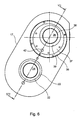
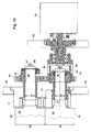
- each double printing unit 13; 14 are in the case of the embodiment in each case in an approximately U-shaped constellation or, in the case of the underlying double printing unit 13, in a constellation corresponding to an inverted U to form a respective bridge pressure unit 13; 14, wherein the two bridge pressure units 13; 14 are arranged one above the other and together define an H-pressure unit 01.
- Each printing unit of each bridge printing unit 13; 14 are the usual peripheral units such as inking unit, dampening unit o. The like. Assigned in a manner not shown.
- the cylinders 03; 04; 06; 07 or 08; 09; 11; 12 of each bridge printing unit 13; 14 are mounted on both sides respectively on or in an insert 17 and 18, which is in each case detachably fixed to the side frame 02.
- the inserts 17; 18 are also bells 17; 18 called.
- the storage of the cylinder 03; 04; 06; 07 on the mutually provided inserts 17 of the bridge printing unit 13 is in particular also from Fig. 2 and from Fig. 3 clear.
- the storage of the cylinder 08; 09; 11; 12 at the two upper inserts 18 of the upper Double printing unit 14 is corresponding, but mirror-symmetrical.
- At least the transfer cylinder 06; 07; 08; 09 are each at least between a print-on position in which they on the printing substrate 16 and the respective opposite transfer cylinder 06; 07; 08; Abut 09, and a print-off position in which they from the printing substrate 16 and the respective opposite transfer cylinder 06; 07; 08; 09 are parked, arranged movably.
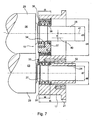
- Fig. 4 to 7 show the storage of a cylinder 03, which may be a forme cylinder 03, and a cylinder 06, which may be a transfer cylinder 06, on an insert 17.
- the forme cylinder 03 and the transfer cylinder 06 may, for example, the printing cylinder 03; 06 one of the printing units of the bridge printing units 13; 14 of the H-printing unit 01 according to Fig. 1 be.
- the other printing units of the bridge printing units 13; 14 may be designed accordingly.
- the insert 17, which is received in a manner not shown here in a corresponding recess of the side frame 02 of the printing press and about its peripheral collar 21 by means of suitable fastening means on the side frame 02nd can be fixed, has two in the axial direction of the cylinder 03; 06 extending through holes 22; 23, through which the pins 24; 26 of the cylinder 03; 06 extend.
- In each through hole 22; 23 is a bearing 19; 27 is arranged, via which the respective pin 24 or 26 on the insert 17 and here on the side frame 02 of the printing press for rotation of the forme cylinder 03 and the transfer cylinder 06 is mounted about its respective axis.
- the bearing 27 for mounting the forme cylinder 03 is designed as a rolling bearing 27.
- the bearing 27 is formed as a cylindrical roller bearing 27 with a tapered inner ring whose shape corresponds to the tapered shape of the corresponding, opposite portion of the pin 24 so that the bearing clearance can be adjusted by moving the inner ring of the bearing 27 in the axial direction.
- the reference numeral 33 denotes a cover plate 33, which covers the bearing 27 on the inner side 31 of the insert 17.
- the axial length I4 of the bearing 27 is significantly smaller than the thickness measured in the axial direction or axial length I5 of the insert 17 or the bell 17, in the case of the embodiment less than half the thickness I5 of the insert 17. Furthermore, the thickness D1 of the side frame 02 is substantially smaller than the thickness I5 of the insert 17.
- the insert 17 is fixed with its the bale 28 of the cylinder 03 facing away, the collar 21 having side in or on the side frame 02.
- the bearing 27 is arranged in the through hole 22 substantially flush with the bale 28 facing inside 31 of the insert, resulting in a high bearing stiffness.
- the bale 28 of the forme cylinder 03 facing end face of the bush 32 acts on the inner ring of the bearing 27.
- the bale 28 of the forme cylinder 03rd facing away from the end face of the bushing 32 acts an adjusting device not shown here or an adjusting mechanism for the axial adjustment or adjustment of the cylinder 03 relative to the insert 17 and thus relative to the side frame 02nd
- a gear to drive the cylinder 03 may be provided. Possibly. can also be provided a second gear to drive a color and / or dampening unit.
- the bearing 19 for mounting the transfer cylinder 06 is formed as a 3-ring eccentric 19.
- the axial length I3 of the bearing 19 corresponds approximately to that of the bearing 27 and is also significantly smaller than the thickness measured in the axial direction I5 of the insert 17 and the bell 17, in the case of the embodiment, therefore less than half the thickness of the insert I5 17th
- the bearing 19 is in turn arranged substantially flush with the bale 29 of the transfer cylinder 06 or the bale 28 of the forme cylinder 03 facing inside 31 of the insert 17 in the through hole 23, which in turn results in a high bearing stiffness.
- the 3-ring eccentric bearing 19 has an inner ring 34, an outer ring 36 and an eccentric ring 37 arranged between inner ring 34 and outer ring 36. Between the inner ring 34 and the eccentric ring 37 on the one hand and between the eccentric ring 37 and the outer ring 36 on the other hand each designed as a cylindrical roller bearing bearings are provided. By means of a retaining ring 38, the inner ring 34 is held in position.
- the inner surface of the inner ring 34 is in turn formed conically corresponding to the tapered shape of the corresponding, opposite portion of the pin 26 of the cylinder 06th
- the bore 39, z. B. bearing bore 39 of the eccentric ring 37 for receiving the inner ring 34 and the locking ring 38 is eccentric, so that the axis of rotation 41 of the pin 26 and thus the transfer cylinder 06 is mounted eccentrically to the axis 40 of the through hole 23 in the insert 17 and thus in the side frame 02 ,
- the eccentric ring 37 By rotating or pivoting the eccentric ring 37, the spatial position of the axis of rotation 41 relative to the insert 17 and the side frame 02 can be varied, whereby it is possible to turn off the transfer cylinder 06 from the forme cylinder 03 or to hire them.
- this can be coupled with an adjusting device, not shown here, for example via a bolt inserted into a bore 42.
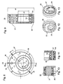
- Fig. 8 to 13 show the above-described 3-ring eccentric bearing 19 again in somewhat greater detail.
- the arrangement is such that on one side of the printing unit 13, the pin 24; 26 of the printing cylinder 03; 04; 06; 07 protrude in the axial direction on the outside outer side 45 of the insert 17 and thus also on the corresponding outer side of the side frame 02.
- This side of the printing unit 13 is the drive side, at which the drives not shown here for the rotation of the printing cylinder 03; 04; 06; 07 and possibly other components and possibly also a circumferential register means 72 are arranged (see. Fig. 16 ).
- eccentric actuators 43 are arranged together with associated drives, by means of which the respective angular position of the eccentric rings 37 is variable.
- the eccentric actuators 43 of this page are particularly in Fig. 14 good to see.
- the two eccentric actuators 43 shown there are with respect to a vertical Sectional plane of the printing unit 13 formed mirror-inverted and it is therefore sufficient to describe only one of the two eccentric actuators 43.
- the eccentric actuating device 43 comprises a drive 49 and a pivoting lever 46 mounted pivotably about a pivot axis 44 with a first lever arm 47 which is drivingly connected to the eccentric ring 37 of the 3-ring eccentric bearing 19, and with a second lever arm 48, which the drive 49, z. B. drive motor 49, for example, a fluid drive 49 with a cylinder-piston assembly 49 is connected.
- a stop arm 51 is formed, which extends in the direction of the median plane of the printing unit 13 toward and abutting a central stop block 52, the two eccentric actuators 43 and their two stop arms 51 an adjustable stop, for example for a exact pressure-on position of the transfer cylinder 06, defined.
- the stop position can be adjusted by means of adjusting screws 53 received in the stop block 52.
- the pivot lever 46 has a partially cylindrical in the case of the embodiment, in the axial direction from the outside into the through hole 23 of the insert 17 extending into coupling portion 54, via which a pivotal movement of the pivot lever 46 is transmitted to the eccentric ring 37 to the effect that the eccentric 37th rotated by a corresponding amount and thus the associated transfer cylinder 06 is pivoted by a corresponding amount.
- a synchronization device 56 is provided for each eccentric actuating device 43, cf. also Fig. 15 .
- Each synchronization device 56 comprises a spindle 57 which extends parallel to the cylinder axes from one side of the printing unit 13 to the other side of the printing unit 13 and at its two ends in each case one Swivel arm 58 carries, whose free end in the case of in Fig. 14 shown printing unit side by means of a push rod 59 and a coupling 59 is coupled to the pivot lever 46 (in Fig. 14 is also on the right side also present push rod 59 is not shown).
- FIG. 15 shown printing unit are for synchronous adjustment of the local 3-ring eccentric bearing 19 corresponding pivot lever 46 (including common stop block 52) provided and the local pivot arms 58 are correspondingly connected via coupling 59 with these pivot levers 46 drivingly connected.
- At least the eccentric actuators 43 of in Fig. 14 shown one side of the printing unit 01 can be attached or mounted on the side frame 02, but preferably on a plate-shaped support 61 and a support plate 61 which is spaced from the side frame 02 to the outside and on the side frame 02, for example by means of bolts 62 releasably fixed ( see. Fig. 2 ).
- the pivot lever 46 together with stop block 52 of the other side can be stored or attached directly to the insert 17 and from there via the through holes 23 of the insert 17 to the eccentric rings 37 of the 3-ring eccentric 19 engage.
- Fig. 16 shows the drive side of the bridge printing unit 13, so the right side in the illustration according to Fig. 2 ,
- the pins 24; 26 of the cylinder 03; 06 protrude beyond the outside of the insert 17.
- On the pins 24 and 26 of the cylinder 03 and 04 are bushings 63; 64 attached, which are each displaceable in the axial direction by a certain amount and their respective first, the bale 28 and 29 of the cylinder 03; 06 facing end face with the inner ring of the bearing 27 and the inner ring 34 of the 3-ring eccentric bearing 19 cooperate.
- the bale 28 and 29 of the cylinder 03; 06 facing away from the end face of the sleeve 63 and 64 acts an adjustment 66 and 67, z.
- a carrier 69 in the form of a support plate 69 is arranged spaced apart from the side frame 02 and fixed releasably, for example by means of bolts 71 on the side frame 02, cf. also Fig. 2 ,
- This support plate 69 can in particular carry a circumferential register device 72, which is drivingly coupled via the bushing 63 to the journal 24 of the forme cylinder 03 and by means of which the respective circumferential register can be adjusted.
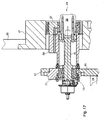
- Fig. 17 again shows the operating side of the bridge printing unit 13, so the left side in the illustration according to Fig. 2 .
- the carrier 61 in the form of a support plate 61 is spaced from the side frame 02 outwardly and releasably fixed, for example by means of bolts 62 not shown here on the side frame 02.
- This carrier plate 61 may in particular also carry a thrust bearing device 73 and possibly also a side register device 74.
- the thrust bearing 73 is mounted on the eccentric bearing 77 in the support plate 61, coupled via the pin extension 76 with the pin 26 of the transfer cylinder 06 and fixes the axial position of the transfer cylinder 06.
- the side register means 74 By means of the side register means 74, the axial position of the forme cylinder 03, so its position along its axis of rotation, changeable and thus the respective correct side register of the forme cylinder 03 adjustable.
- the dimensions of the components of the printing unit 13 are selected so that, in conjunction with the selected arrangement of the components with a comparatively compact overall dimensions, a reliable and stable operation results, in particular, a high rigidity of the bearing of the cylinder 03; 04; 06; 07, which increases print quality.
- the following dimensions or size ratios are preferably used:
- a web width I1 of the printing material web 16 of preferably 1000 mm +/- 10% results in an axial length 12 of the bale 28; 29 of the cylinder 03; 04; 06; 07 of preferably 950 mm to 1250 mm, in particular from 1000 mm to 1200 mm, for example, of 1110 mm +/- 5%.
- the diameter d2 of each pin 24; 26 of the cylinder 03; 04; 06; 07 is preferably 55 mm to 75 mm, in particular 60 mm to 70 mm, for example 65 mm +/- 5%.
- each bale 28; 28 of the cylinder 03; 04; 06; As a rule, 07 varies depending on the application and can be, for example, 150 mm to 250 mm, in particular 169 mm to 222 mm +/- 5% or 195 mm +/- 15%.
- the 3-ring eccentric bearing 19 of the transfer cylinder 06 or 07 may have an outer diameter d4 of preferably 130 mm to 190 mm, in particular from 145 mm to 175 mm, for example of 160 mm +/- 5%, and an inner diameter d5 corresponding to Diameter d2 of the pins 24; 26, preferably 55 mm to 75 mm, in particular 60 mm to 70 mm, for example 65 mm +/- 5%.
- the eccentricity e of the 3-ring eccentric bearing 19 may preferably be 8 mm to 24 mm, in particular from 12 mm to 20 mm, for example 16 mm +/- 10%; Furthermore, the eccentricity e of the 3-ring eccentric bearing 19 may preferably be 1/10 +/- 50%, in particular 1/10 +/- 25%, for example 1/10 +/- 10% of the outer diameter d4 of the 3-ring eccentric Exzenterlagers 19 amount.
- the axial length 13 of the 3-ring eccentric bearing 19 may preferably be 40 mm to 70 mm, in particular 50 mm to 62 mm, for example 56 mm +/- 5%.
- the bearing 27 of the forme cylinder 03 or 04 may have an outer diameter d6 of preferably 80 mm to 120 mm, in particular 90 mm to 110 mm, for example of 100 mm +/- 5%, and an inner diameter d7 corresponding to the diameter d2 of the pins 24; 26, preferably 55 mm to 75 mm, in particular 60 mm to 70 mm, for example 65 mm +/- 5%.
- the axial length I4 of the bearing 27 may preferably be 35 mm to 65 mm, in particular 45 mm to 55 mm, for example 50 mm +/- 5%.
- the side frame 02 or, more precisely, the frame plates 02 arranged on both sides of the printing unit 01 or 13 can have a thickness D1 of 30 mm to 100 mm, preferably of 40 mm to 80 mm, for example of 60 mm +/- 10%. exhibit.
- the support plates 61; 69 in contrast, can be dimensioned somewhat smaller in accordance with the weaker load, preferably with a thickness D2 of 25 mm to 55 mm in each case, in particular of 35 mm to 45 mm, for example of 40 mm +/- 5%.
- the distance a1 of the support plate 61 to the side frame 02 is preferably 60 mm to 120 mm, in particular 75 to 105 mm, for example, 93 mm +/- 10%.
- the drive side of the printing unit 01 shown on the right is the distance a2 of the local support plate 69 to the side frame 02 (clear width) preferably 150 mm to 300 mm, in particular 200 to 275 mm, for example 250 mm +/- 5%.
- the arranged on both sides of the printing unit 01 frame plates 02 of the side frame 02 are at a distance a3 (clear width) of preferably 1,000 mm to 1,500 mm, in particular 1,150 mm to 1,400 mm, for example, 1280 mm +/- 5% spaced, the distance a4 the mutually facing sides of the bale 28 or 29 and the adjacent frame plate 02 is preferably 70 mm to 100 mm, in particular 75 mm to 95 mm, for example 85 mm +/- 5%.
- a preferred distance a6 (clear width) between a bale 28; 29 associated inside of a side frame 02 and the bale 28; 29 associated inside 31 of an insert 17 held therein may preferably be 60 mm to 100 mm, in particular 70 mm to 90 mm, for example 80 mm +/- 10%.
- the axial length 15 of the insert 17 may preferably be 80 mm to 150 mm, in particular 100 mm to 135 mm, for example 120 mm +/- 10%.
- the distance a5 between the facing sides of the bale 28; 29 and the associated bearing 19; 27 may preferably be 5 mm to 20 mm, in particular 7.5 mm to 15 mm, for example, as shown 10 mm +/- 10%.
- a preferred range of the ratio of axial length I2 of a bale 28; 28 to the distance a5 between bale 28; 29 and bearing 27; 19 in the range between 50 and 250, in particular in the range between 75 and 150 are.
- a preferable range of the ratio of diameter d3 of a bale 28; 29 to the distance a5 between bale 28; 29 and bearing 27; 19 are in the range between 8 and 40.
- a preferred range of the ratio of an axial length 12 of the bale 28; 29 to the diameter d3 of the bale 28; 29 are between 4.3 and 7.4, in particular between 5 and 6.5.
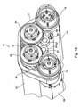
- a common drive motor 88 is provided which via a gear 89, for example a drive pinion 89 drives a gear 91, which in turn is in engagement with two further gears 92 and 93.
- the gear 91 may also be omitted, so that the drive pinion 89 with the gears 92 and 93 is engaged.
- the gear 92 is in driving connection with the gear 78 of the forme cylinder 03 and the gear 93 with the gear 86 of the forme cylinder 11.
- the gear 93 is formed as an adjustable double wheel to the position (register) of the two double printing units 13; 14 to adjust.
- the gear 92 may be formed as a clutch for stopping the lower double printing unit 13.
- the drive motor 88 may be a position-controlled and / or speed-controlled drive motor 88 and, in particular, fixed to the device and, in particular, coaxial with the drive pinion 89 or with the gear 91.
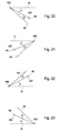
- the angle ⁇ is 28 ° and the angle ⁇ is 13 °.
- the angle ⁇ is 24 ° and the angle ⁇ is 19 °.
- the angle ⁇ is 28 ° and the angle ⁇ is 13 °.
- the angle ⁇ is 24 ° and the angle ⁇ is 19 °.
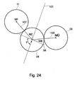
- the arrangement is preferably selected overall so that when adjusting the cylinder position near the pressure-on position, a change in the axial distance of the corresponding transfer cylinder, z. B. the transfer cylinder 08 to the adjacent transfer cylinder, z. B. to the transfer cylinder 09 and a change in the axial distance of the corresponding transfer cylinder 08 to the associated form cylinder, z. B. to the forme cylinder 11 in a ratio of at least approximately 1: 1.
- This condition is met in the case of the embodiment described here. This condition will generally be satisfied, for example, especially if, as in Fig.
- the center MZ of the transfer cylinder 08 and the center MB of the corresponding eccentric bushing 19 are at least approximately on a straight line 98 which is perpendicular to an angle bisector 101 between that line 102, which connects the center MZ with the center MF of the associated forme cylinder 11 and that straight line 103 which connects the center MZ with the center MÜ of the adjacent transfer cylinder 09.
- the straight line 98 should preferably include an angle ⁇ between 60 ° and 120 °, in particular an angle ⁇ between 75 ° and 105 °, with the bisector 101.
- the drive motor 49 is not in positive drive connection to another printing unit.
- the two gears 92, 93 are exemplary on the side frame 02 outside of the inserts 17; 18 stored.
Landscapes
- Engineering & Computer Science (AREA)
- Mechanical Engineering (AREA)
- Rotary Presses (AREA)
Claims (8)
- Unité d'impression d'une machine d'impression avec deux groupes d'impression doubles (13 ; 14) superposés, chaque groupe d'impression double (13 ; 14) comportant deux cylindres porte-cliché (03 ; 04 et 11 ; 12) et deux cylindres de transfert (06 ; 07 ; et 08 ; 09), les tourillons frontaux (24 ; 26) des cylindres porte-cliché (03 ; 04 et 11 ; 12) et des cylindres de transfert (06 ; 07 ; et 08 ; 09) d'un groupe d'impression double (13 ; 14) étant montés de part et d'autre sur un engagement (17 ; 18), lequel est quant à lui disposé de manière amovible sur et/ou dans le châssis latéral (02) de la machine d'impression, caractérisée en ce que les quatre cylindres porte-cliché (03 ; 04 ; 11 ; 12) et les quatre cylindres de transfert (06 ; 07 ; 08 ; 09) de l'unité d'impression (01) sont entraînables au moyen d'un seul moteur d'entraînement (49) commun, en ce que chacun des deux groupes d'impression doubles (13 ; 14) est entraîné par une roue dentée (93 ; 92), en ce que chacune des deux roues dentées (93 ; 92) s'engrène avec une roue dentée (78 ; 86) disposée sur un cylindre porte-cliché (03 ; 04 ; 11 ; 12), en ce que les deux roues dentées (92 ; 93) s'engrènent avec une roue dentée (91) ou un pignon d'entraînement (89) commun, en ce que le moteur d'entraînement (88) est disposé de manière à entraîner la roue dentée (91) ou le pignon d'entraînement (89), en ce que la roue dentée (93) qui s'engrène avec la roue dentée (78) disposée sur le cylindre porte-cliché (03) du groupe d'impression double supérieur (14) est réalisée sous forme de denture double réglable permettant d'ajuster la position des deux groupes d'impression doubles (13 ; 14).
- Unité d'impression selon la revendication 1, caractérisée en ce que la roue dentée (92) qui s'engrène avec la roue dentée (78) disposée sur le cylindre porte-cliché (03) du groupe d'impression double inférieur (13) est réalisée sous forme d'embrayage pour la mise à l'arrêt du groupe d'impression double inférieur (13).
- Unité d'impression selon la revendication 1, caractérisée en ce que le moteur d'entraînement (88) est disposé coaxialement à la roue dentée (91) ou au pignon d'entraînement (89).
- Unité d'impression selon la revendication 1, caractérisée en ce que ladite unité d'impression (01) comporte deux engagements (17 ; 18).
- Unité d'impression selon la revendication 1, caractérisée en ce que le moteur d'entraînement (49) est en liaison d'entraînement avec un cylindre porte-cliché (03 ; 04 et 11 ; 12) de chaque groupe d'impression double (13 ; 14).
- Unité d'impression selon la revendication 1, caractérisée en ce que le moteur d'entraînement (49) n'est pas en liaison d'entraînement mécanique avec une autre unité d'impression.
- Unité d'impression selon la revendication 1, caractérisée en ce que le moteur d'entraînement (49) est fixé sur le châssis latéral (02), extérieurement aux engagements (17 ; 18).
- Unité d'impression selon la revendication 1, caractérisée en ce que les deux roues dentées (92 ; 93) sont montées sur le châssis latéral (02), extérieurement aux engagements (17 ; 18).
Applications Claiming Priority (1)
| Application Number | Priority Date | Filing Date | Title |
|---|---|---|---|
| DE200610054381 DE102006054381A1 (de) | 2006-11-17 | 2006-11-17 | Druckeinheit einer Druckmaschine mit zwei übereinander angeordneten Doppeldruckwerken |
Publications (3)
| Publication Number | Publication Date |
|---|---|
| EP1923213A2 EP1923213A2 (fr) | 2008-05-21 |
| EP1923213A3 EP1923213A3 (fr) | 2011-01-26 |
| EP1923213B1 true EP1923213B1 (fr) | 2012-11-14 |
Family
ID=39145413
Family Applications (1)
| Application Number | Title | Priority Date | Filing Date |
|---|---|---|---|
| EP20070114643 Not-in-force EP1923213B1 (fr) | 2006-11-17 | 2007-08-21 | Unité d'impression d'une presse dotée de deux doubles groupes d'impression agencés l'un sur l'autre |
Country Status (2)
| Country | Link |
|---|---|
| EP (1) | EP1923213B1 (fr) |
| DE (1) | DE102006054381A1 (fr) |
Families Citing this family (1)
| Publication number | Priority date | Publication date | Assignee | Title |
|---|---|---|---|---|
| DE102011089197A1 (de) * | 2011-12-20 | 2013-06-20 | Koenig & Bauer Aktiengesellschaft | Seitengestell einer Druckmaschine |
Family Cites Families (5)
| Publication number | Priority date | Publication date | Assignee | Title |
|---|---|---|---|---|
| DE4430693B4 (de) * | 1994-08-30 | 2005-12-22 | Man Roland Druckmaschinen Ag | Antriebe für eine Rollenrotations-Offsetdruckmaschine |
| US7216585B2 (en) * | 2001-01-24 | 2007-05-15 | Goss International Americas, Inc. | Shaftless motor drive for a printing press with an anilox inker |
| DE10129762B4 (de) * | 2001-06-20 | 2004-07-29 | Koenig & Bauer Ag | Druckeinheit |
| CN1781703A (zh) * | 2001-08-03 | 2006-06-07 | 柯尼格及包尔公开股份有限公司 | 印刷机的印刷装置 |
| EP1932664A2 (fr) * | 2001-11-08 | 2008-06-18 | Koenig & Bauer AG | Dispositif d'entrainement d'un groupe d'impression |
-
2006
- 2006-11-17 DE DE200610054381 patent/DE102006054381A1/de not_active Withdrawn
-
2007
- 2007-08-21 EP EP20070114643 patent/EP1923213B1/fr not_active Not-in-force
Also Published As
| Publication number | Publication date |
|---|---|
| EP1923213A2 (fr) | 2008-05-21 |
| EP1923213A3 (fr) | 2011-01-26 |
| DE102006054381A1 (de) | 2008-05-21 |
Similar Documents
| Publication | Publication Date | Title |
|---|---|---|
| EP0813959B1 (fr) | Cylindre entraíné | |
| WO2005097505A2 (fr) | Unite d'impression d'une rotative a bobines | |
| EP1923214B1 (fr) | Unité d'impression d'une presse dotée de deux doubles groupes d'impressions agencés l'un sur l'autre | |
| WO2005096691B1 (fr) | Unites d'impression d'une rotative a bobines | |
| DE102007017097B4 (de) | Druckzylinder-Wechselvorrichtung für druckenlängenveränderbare Druckwerke in einer Vollrotations-Druckmaschine | |
| EP2523810B1 (fr) | Dispositifs de support d'un ou de plusieurs cylindres d'une machine à imprimer | |
| EP1280666B1 (fr) | Mecanisme permettant d'ajuster l'ecart entre les axes de rotation de cylindres | |
| EP1923213B1 (fr) | Unité d'impression d'une presse dotée de deux doubles groupes d'impression agencés l'un sur l'autre | |
| DE1241464B (de) | Einrichtung an einer Rotationsdruckmaschine zum Schraegstellen der Achse des Formzylinders gegenueber derjenigen des mit ihm zusammenwirkenden Druckwerkzylinders | |
| DE10046367B4 (de) | Antrieb einer Druckeinheit | |
| DE102006054380B4 (de) | Anordnung in einer Druckmaschine mit mindestens einem Plattenzylinder und mindestens einem Übertragungszylinder | |
| DE10014040B4 (de) | Welle zum Synchronisieren einer Stellbewegung | |
| DE4436584C2 (de) | Plattenzylinderlagerung | |
| EP1042123B1 (fr) | Rouleau | |
| EP2114681B1 (fr) | Groupe d'impression d'une presse rotative et procédé de lavage d'un groupe de mouillage d'un groupe d'impression | |
| EP0353652B1 (fr) | Dispositif supplémentaire pour montage sur une machine d'impression offset | |
| DE102007011045B4 (de) | Druckmaschine | |
| DE10331605B3 (de) | Verstellbar gelagerte Walze | |
| DE4401289C2 (de) | Zylinderanstellvorrichtung | |
| DE10046375B4 (de) | Antrieb einer Druckeinheit | |
| DE102010000891B4 (de) | Vorrichtungen zur Lagerung von Druckzylindern einer Druckmaschine | |
| DE102011082679B4 (de) | Vorrichtung und Verfahren zur Befestigung und/oder Justage einer Lagervorrichtung eines Druckwerkszylinders | |
| DE102010030331B4 (de) | Vorrichtungen zur Lagerung eines oder mehrerer Zylinder einer Druckmaschine | |
| DE102007000831B4 (de) | Walze einer Rotationsdruckmaschine und Verfahren zum Einstellen einer Auftragswalze | |
| DE4139326C2 (de) | Vorrichtung zum Einstellen des Umfangsregisters an Rotationsdruckmaschinen |
Legal Events
| Date | Code | Title | Description |
|---|---|---|---|
| PUAI | Public reference made under article 153(3) epc to a published international application that has entered the european phase |
Free format text: ORIGINAL CODE: 0009012 |
|
| AK | Designated contracting states |
Kind code of ref document: A2 Designated state(s): AT BE BG CH CY CZ DE DK EE ES FI FR GB GR HU IE IS IT LI LT LU LV MC MT NL PL PT RO SE SI SK TR |
|
| AX | Request for extension of the european patent |
Extension state: AL BA HR MK RS |
|
| PUAL | Search report despatched |
Free format text: ORIGINAL CODE: 0009013 |
|
| AK | Designated contracting states |
Kind code of ref document: A3 Designated state(s): AT BE BG CH CY CZ DE DK EE ES FI FR GB GR HU IE IS IT LI LT LU LV MC MT NL PL PT RO SE SI SK TR |
|
| AX | Request for extension of the european patent |
Extension state: AL BA HR MK RS |
|
| 17P | Request for examination filed |
Effective date: 20110121 |
|
| 17Q | First examination report despatched |
Effective date: 20110224 |
|
| AKX | Designation fees paid |
Designated state(s): AT BE BG CH CY CZ DE DK EE ES FI FR GB GR HU IE IS IT LI LT LU LV MC MT NL PL PT RO SE SI SK TR |
|
| GRAP | Despatch of communication of intention to grant a patent |
Free format text: ORIGINAL CODE: EPIDOSNIGR1 |
|
| GRAS | Grant fee paid |
Free format text: ORIGINAL CODE: EPIDOSNIGR3 |
|
| GRAA | (expected) grant |
Free format text: ORIGINAL CODE: 0009210 |
|
| AK | Designated contracting states |
Kind code of ref document: B1 Designated state(s): AT BE BG CH CY CZ DE DK EE ES FI FR GB GR HU IE IS IT LI LT LU LV MC MT NL PL PT RO SE SI SK TR |
|
| REG | Reference to a national code |
Ref country code: GB Ref legal event code: FG4D Free format text: NOT ENGLISH |
|
| REG | Reference to a national code |
Ref country code: CH Ref legal event code: EP Ref country code: AT Ref legal event code: REF Ref document number: 583734 Country of ref document: AT Kind code of ref document: T Effective date: 20121115 |
|
| REG | Reference to a national code |
Ref country code: IE Ref legal event code: FG4D Free format text: LANGUAGE OF EP DOCUMENT: GERMAN |
|
| REG | Reference to a national code |
Ref country code: DE Ref legal event code: R096 Ref document number: 502007010856 Country of ref document: DE Effective date: 20130103 |
|
| REG | Reference to a national code |
Ref country code: NL Ref legal event code: VDEP Effective date: 20121114 |
|
| REG | Reference to a national code |
Ref country code: LT Ref legal event code: MG4D |
|
| PG25 | Lapsed in a contracting state [announced via postgrant information from national office to epo] |
Ref country code: ES Free format text: LAPSE BECAUSE OF FAILURE TO SUBMIT A TRANSLATION OF THE DESCRIPTION OR TO PAY THE FEE WITHIN THE PRESCRIBED TIME-LIMIT Effective date: 20130225 Ref country code: SE Free format text: LAPSE BECAUSE OF FAILURE TO SUBMIT A TRANSLATION OF THE DESCRIPTION OR TO PAY THE FEE WITHIN THE PRESCRIBED TIME-LIMIT Effective date: 20121114 Ref country code: FI Free format text: LAPSE BECAUSE OF FAILURE TO SUBMIT A TRANSLATION OF THE DESCRIPTION OR TO PAY THE FEE WITHIN THE PRESCRIBED TIME-LIMIT Effective date: 20121114 Ref country code: LT Free format text: LAPSE BECAUSE OF FAILURE TO SUBMIT A TRANSLATION OF THE DESCRIPTION OR TO PAY THE FEE WITHIN THE PRESCRIBED TIME-LIMIT Effective date: 20121114 |
|
| PG25 | Lapsed in a contracting state [announced via postgrant information from national office to epo] |
Ref country code: LV Free format text: LAPSE BECAUSE OF FAILURE TO SUBMIT A TRANSLATION OF THE DESCRIPTION OR TO PAY THE FEE WITHIN THE PRESCRIBED TIME-LIMIT Effective date: 20121114 Ref country code: PL Free format text: LAPSE BECAUSE OF FAILURE TO SUBMIT A TRANSLATION OF THE DESCRIPTION OR TO PAY THE FEE WITHIN THE PRESCRIBED TIME-LIMIT Effective date: 20121114 Ref country code: GR Free format text: LAPSE BECAUSE OF FAILURE TO SUBMIT A TRANSLATION OF THE DESCRIPTION OR TO PAY THE FEE WITHIN THE PRESCRIBED TIME-LIMIT Effective date: 20130215 Ref country code: CY Free format text: LAPSE BECAUSE OF FAILURE TO SUBMIT A TRANSLATION OF THE DESCRIPTION OR TO PAY THE FEE WITHIN THE PRESCRIBED TIME-LIMIT Effective date: 20121114 Ref country code: SI Free format text: LAPSE BECAUSE OF FAILURE TO SUBMIT A TRANSLATION OF THE DESCRIPTION OR TO PAY THE FEE WITHIN THE PRESCRIBED TIME-LIMIT Effective date: 20121114 Ref country code: PT Free format text: LAPSE BECAUSE OF FAILURE TO SUBMIT A TRANSLATION OF THE DESCRIPTION OR TO PAY THE FEE WITHIN THE PRESCRIBED TIME-LIMIT Effective date: 20130314 |
|
| PG25 | Lapsed in a contracting state [announced via postgrant information from national office to epo] |
Ref country code: DK Free format text: LAPSE BECAUSE OF FAILURE TO SUBMIT A TRANSLATION OF THE DESCRIPTION OR TO PAY THE FEE WITHIN THE PRESCRIBED TIME-LIMIT Effective date: 20121114 Ref country code: BG Free format text: LAPSE BECAUSE OF FAILURE TO SUBMIT A TRANSLATION OF THE DESCRIPTION OR TO PAY THE FEE WITHIN THE PRESCRIBED TIME-LIMIT Effective date: 20130214 Ref country code: EE Free format text: LAPSE BECAUSE OF FAILURE TO SUBMIT A TRANSLATION OF THE DESCRIPTION OR TO PAY THE FEE WITHIN THE PRESCRIBED TIME-LIMIT Effective date: 20121114 Ref country code: SK Free format text: LAPSE BECAUSE OF FAILURE TO SUBMIT A TRANSLATION OF THE DESCRIPTION OR TO PAY THE FEE WITHIN THE PRESCRIBED TIME-LIMIT Effective date: 20121114 Ref country code: CZ Free format text: LAPSE BECAUSE OF FAILURE TO SUBMIT A TRANSLATION OF THE DESCRIPTION OR TO PAY THE FEE WITHIN THE PRESCRIBED TIME-LIMIT Effective date: 20121114 |
|
| PG25 | Lapsed in a contracting state [announced via postgrant information from national office to epo] |
Ref country code: IT Free format text: LAPSE BECAUSE OF FAILURE TO SUBMIT A TRANSLATION OF THE DESCRIPTION OR TO PAY THE FEE WITHIN THE PRESCRIBED TIME-LIMIT Effective date: 20121114 Ref country code: NL Free format text: LAPSE BECAUSE OF FAILURE TO SUBMIT A TRANSLATION OF THE DESCRIPTION OR TO PAY THE FEE WITHIN THE PRESCRIBED TIME-LIMIT Effective date: 20121114 Ref country code: RO Free format text: LAPSE BECAUSE OF FAILURE TO SUBMIT A TRANSLATION OF THE DESCRIPTION OR TO PAY THE FEE WITHIN THE PRESCRIBED TIME-LIMIT Effective date: 20121114 |
|
| PLBE | No opposition filed within time limit |
Free format text: ORIGINAL CODE: 0009261 |
|
| STAA | Information on the status of an ep patent application or granted ep patent |
Free format text: STATUS: NO OPPOSITION FILED WITHIN TIME LIMIT |
|
| 26N | No opposition filed |
Effective date: 20130815 |
|
| REG | Reference to a national code |
Ref country code: DE Ref legal event code: R097 Ref document number: 502007010856 Country of ref document: DE Effective date: 20130815 |
|
| BERE | Be: lapsed |
Owner name: KOENIG & BAUER A.G. Effective date: 20130831 |
|
| REG | Reference to a national code |
Ref country code: CH Ref legal event code: PL |
|
| GBPC | Gb: european patent ceased through non-payment of renewal fee |
Effective date: 20130821 |
|
| PG25 | Lapsed in a contracting state [announced via postgrant information from national office to epo] |
Ref country code: CH Free format text: LAPSE BECAUSE OF NON-PAYMENT OF DUE FEES Effective date: 20130831 Ref country code: MC Free format text: LAPSE BECAUSE OF FAILURE TO SUBMIT A TRANSLATION OF THE DESCRIPTION OR TO PAY THE FEE WITHIN THE PRESCRIBED TIME-LIMIT Effective date: 20121114 Ref country code: LI Free format text: LAPSE BECAUSE OF NON-PAYMENT OF DUE FEES Effective date: 20130831 |
|
| REG | Reference to a national code |
Ref country code: IE Ref legal event code: MM4A |
|
| REG | Reference to a national code |
Ref country code: FR Ref legal event code: ST Effective date: 20140430 |
|
| PG25 | Lapsed in a contracting state [announced via postgrant information from national office to epo] |
Ref country code: BE Free format text: LAPSE BECAUSE OF NON-PAYMENT OF DUE FEES Effective date: 20130831 |
|
| PG25 | Lapsed in a contracting state [announced via postgrant information from national office to epo] |
Ref country code: IE Free format text: LAPSE BECAUSE OF NON-PAYMENT OF DUE FEES Effective date: 20130821 Ref country code: GB Free format text: LAPSE BECAUSE OF NON-PAYMENT OF DUE FEES Effective date: 20130821 |
|
| PG25 | Lapsed in a contracting state [announced via postgrant information from national office to epo] |
Ref country code: FR Free format text: LAPSE BECAUSE OF NON-PAYMENT OF DUE FEES Effective date: 20130902 |
|
| REG | Reference to a national code |
Ref country code: AT Ref legal event code: MM01 Ref document number: 583734 Country of ref document: AT Kind code of ref document: T Effective date: 20130821 |
|
| PG25 | Lapsed in a contracting state [announced via postgrant information from national office to epo] |
Ref country code: AT Free format text: LAPSE BECAUSE OF NON-PAYMENT OF DUE FEES Effective date: 20130821 |
|
| PG25 | Lapsed in a contracting state [announced via postgrant information from national office to epo] |
Ref country code: MT Free format text: LAPSE BECAUSE OF FAILURE TO SUBMIT A TRANSLATION OF THE DESCRIPTION OR TO PAY THE FEE WITHIN THE PRESCRIBED TIME-LIMIT Effective date: 20121114 Ref country code: TR Free format text: LAPSE BECAUSE OF FAILURE TO SUBMIT A TRANSLATION OF THE DESCRIPTION OR TO PAY THE FEE WITHIN THE PRESCRIBED TIME-LIMIT Effective date: 20121114 |
|
| PG25 | Lapsed in a contracting state [announced via postgrant information from national office to epo] |
Ref country code: LU Free format text: LAPSE BECAUSE OF NON-PAYMENT OF DUE FEES Effective date: 20130821 Ref country code: HU Free format text: LAPSE BECAUSE OF FAILURE TO SUBMIT A TRANSLATION OF THE DESCRIPTION OR TO PAY THE FEE WITHIN THE PRESCRIBED TIME-LIMIT; INVALID AB INITIO Effective date: 20070821 |
|
| REG | Reference to a national code |
Ref country code: DE Ref legal event code: R081 Ref document number: 502007010856 Country of ref document: DE Owner name: KOENIG BAUER AG, DE Free format text: FORMER OWNER: KOENIG BAUER AKTIENGESELLSCHAFT, 97080 WUERZBURG, DE Ref country code: DE Ref legal event code: R081 Ref document number: 502007010856 Country of ref document: DE Owner name: KOENIG & BAUER AG, DE Free format text: FORMER OWNER: KOENIG & BAUER AKTIENGESELLSCHAFT, 97080 WUERZBURG, DE |
|
| PG25 | Lapsed in a contracting state [announced via postgrant information from national office to epo] |
Ref country code: IS Free format text: LAPSE BECAUSE OF FAILURE TO SUBMIT A TRANSLATION OF THE DESCRIPTION OR TO PAY THE FEE WITHIN THE PRESCRIBED TIME-LIMIT Effective date: 20121114 |
|
| PGFP | Annual fee paid to national office [announced via postgrant information from national office to epo] |
Ref country code: DE Payment date: 20180823 Year of fee payment: 12 |
|
| REG | Reference to a national code |
Ref country code: DE Ref legal event code: R119 Ref document number: 502007010856 Country of ref document: DE |
|
| PG25 | Lapsed in a contracting state [announced via postgrant information from national office to epo] |
Ref country code: DE Free format text: LAPSE BECAUSE OF NON-PAYMENT OF DUE FEES Effective date: 20200303 |