EP1923213B1 - Printing unit of a printing press with two double printing groups arranged over each other - Google Patents
Printing unit of a printing press with two double printing groups arranged over each other Download PDFInfo
- Publication number
- EP1923213B1 EP1923213B1 EP20070114643 EP07114643A EP1923213B1 EP 1923213 B1 EP1923213 B1 EP 1923213B1 EP 20070114643 EP20070114643 EP 20070114643 EP 07114643 A EP07114643 A EP 07114643A EP 1923213 B1 EP1923213 B1 EP 1923213B1
- Authority
- EP
- European Patent Office
- Prior art keywords
- printing
- cylinder
- printing unit
- double
- eccentric
- Prior art date
- Legal status (The legal status is an assumption and is not a legal conclusion. Google has not performed a legal analysis and makes no representation as to the accuracy of the status listed.)
- Not-in-force
Links
Images


Classifications
-
- B—PERFORMING OPERATIONS; TRANSPORTING
- B41—PRINTING; LINING MACHINES; TYPEWRITERS; STAMPS
- B41F—PRINTING MACHINES OR PRESSES
- B41F13/00—Common details of rotary presses or machines
- B41F13/08—Cylinders
Definitions
- the invention relates to a printing unit of a printing machine with two stacked double printing units according to the preamble of claim 1.
- an H-printing unit with two stacked double printing units wherein the end-side pins of the printing unit cylinders are each mounted on an insert, which in turn is detachably arranged on the side frame of the printing press.
- the printing cylinder, in particular the forme cylinder are at least partially adjustable via slide or eccentric.
- WO 98/53995 A1 is a drive for a cylinder of a rotary printing machine in connection with a bridge unit of a H-printing unit known, wherein printing cylinder, in particular transfer cylinders are mounted in eccentric bushings, which in turn are held directly in the side frame.
- Fig. 3 of the EP 0 699 524 A2 is a printing unit with two superimposed double printing units known.
- the transfer cylinders of the double printing units are connected to each other via a chain of wheels.
- the WO 03/000496 A1 shows a printing unit with two stacked double printing units, wherein the cylinders are driven by a common electric motor.
- the invention has for its object to provide a printing unit of a printing machine with two stacked double printing units.
- the achievable with the present invention consist in particular that a particularly space-saving arrangement can be realized with a comparatively simple structure, ease of use and high bearing stiffness.
- a printing unit 01 of a printing machine for example a web-fed rotary printing press, in particular a web-fed rotary offset printing press of a type known per se, on a side frame 02 of the printing press cylinder 03; 04; 06; 07; 08; 09; 11; 12, in particular printing cylinder 03; 04; 06; 07; 08; 09; 11; 12 rotatable about their respective axis and stored drivable in a suitable manner.
- a web-fed rotary printing press in particular a web-fed rotary offset printing press of a type known per se
- the form cylinder 03; 04; 11; 12 can as a plate cylinder 03; 04; 11; 12 and the transfer cylinder 06; 07; 08; 09 as a blanket cylinder 06; 07; 08; 09 be formed.
- the transfer cylinder 06; 07; 08; 09 are in the case of the embodiment described here as impression cylinder 06; 07; 08; 09 trained.
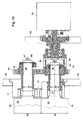
- each double printing unit 13; 14 are in the case of the embodiment in each case in an approximately U-shaped constellation or, in the case of the underlying double printing unit 13, in a constellation corresponding to an inverted U to form a respective bridge pressure unit 13; 14, wherein the two bridge pressure units 13; 14 are arranged one above the other and together define an H-pressure unit 01.
- Each printing unit of each bridge printing unit 13; 14 are the usual peripheral units such as inking unit, dampening unit o. The like. Assigned in a manner not shown.
- the cylinders 03; 04; 06; 07 or 08; 09; 11; 12 of each bridge printing unit 13; 14 are mounted on both sides respectively on or in an insert 17 and 18, which is in each case detachably fixed to the side frame 02.
- the inserts 17; 18 are also bells 17; 18 called.
- the storage of the cylinder 03; 04; 06; 07 on the mutually provided inserts 17 of the bridge printing unit 13 is in particular also from Fig. 2 and from Fig. 3 clear.
- the storage of the cylinder 08; 09; 11; 12 at the two upper inserts 18 of the upper Double printing unit 14 is corresponding, but mirror-symmetrical.
- At least the transfer cylinder 06; 07; 08; 09 are each at least between a print-on position in which they on the printing substrate 16 and the respective opposite transfer cylinder 06; 07; 08; Abut 09, and a print-off position in which they from the printing substrate 16 and the respective opposite transfer cylinder 06; 07; 08; 09 are parked, arranged movably.
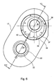
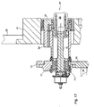
- Fig. 4 to 7 show the storage of a cylinder 03, which may be a forme cylinder 03, and a cylinder 06, which may be a transfer cylinder 06, on an insert 17.
- the forme cylinder 03 and the transfer cylinder 06 may, for example, the printing cylinder 03; 06 one of the printing units of the bridge printing units 13; 14 of the H-printing unit 01 according to Fig. 1 be.
- the other printing units of the bridge printing units 13; 14 may be designed accordingly.
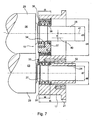
- the insert 17, which is received in a manner not shown here in a corresponding recess of the side frame 02 of the printing press and about its peripheral collar 21 by means of suitable fastening means on the side frame 02nd can be fixed, has two in the axial direction of the cylinder 03; 06 extending through holes 22; 23, through which the pins 24; 26 of the cylinder 03; 06 extend.
- In each through hole 22; 23 is a bearing 19; 27 is arranged, via which the respective pin 24 or 26 on the insert 17 and here on the side frame 02 of the printing press for rotation of the forme cylinder 03 and the transfer cylinder 06 is mounted about its respective axis.
- the bearing 27 for mounting the forme cylinder 03 is designed as a rolling bearing 27.
- the bearing 27 is formed as a cylindrical roller bearing 27 with a tapered inner ring whose shape corresponds to the tapered shape of the corresponding, opposite portion of the pin 24 so that the bearing clearance can be adjusted by moving the inner ring of the bearing 27 in the axial direction.
- the reference numeral 33 denotes a cover plate 33, which covers the bearing 27 on the inner side 31 of the insert 17.
- the axial length I4 of the bearing 27 is significantly smaller than the thickness measured in the axial direction or axial length I5 of the insert 17 or the bell 17, in the case of the embodiment less than half the thickness I5 of the insert 17. Furthermore, the thickness D1 of the side frame 02 is substantially smaller than the thickness I5 of the insert 17.
- the insert 17 is fixed with its the bale 28 of the cylinder 03 facing away, the collar 21 having side in or on the side frame 02.
- the bearing 27 is arranged in the through hole 22 substantially flush with the bale 28 facing inside 31 of the insert, resulting in a high bearing stiffness.
- the bale 28 of the forme cylinder 03 facing end face of the bush 32 acts on the inner ring of the bearing 27.
- the bale 28 of the forme cylinder 03rd facing away from the end face of the bushing 32 acts an adjusting device not shown here or an adjusting mechanism for the axial adjustment or adjustment of the cylinder 03 relative to the insert 17 and thus relative to the side frame 02nd
- a gear to drive the cylinder 03 may be provided. Possibly. can also be provided a second gear to drive a color and / or dampening unit.
- the bearing 19 for mounting the transfer cylinder 06 is formed as a 3-ring eccentric 19.
- the axial length I3 of the bearing 19 corresponds approximately to that of the bearing 27 and is also significantly smaller than the thickness measured in the axial direction I5 of the insert 17 and the bell 17, in the case of the embodiment, therefore less than half the thickness of the insert I5 17th
- the bearing 19 is in turn arranged substantially flush with the bale 29 of the transfer cylinder 06 or the bale 28 of the forme cylinder 03 facing inside 31 of the insert 17 in the through hole 23, which in turn results in a high bearing stiffness.
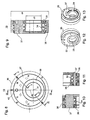
- the 3-ring eccentric bearing 19 has an inner ring 34, an outer ring 36 and an eccentric ring 37 arranged between inner ring 34 and outer ring 36. Between the inner ring 34 and the eccentric ring 37 on the one hand and between the eccentric ring 37 and the outer ring 36 on the other hand each designed as a cylindrical roller bearing bearings are provided. By means of a retaining ring 38, the inner ring 34 is held in position.
- the inner surface of the inner ring 34 is in turn formed conically corresponding to the tapered shape of the corresponding, opposite portion of the pin 26 of the cylinder 06th
- the bore 39, z. B. bearing bore 39 of the eccentric ring 37 for receiving the inner ring 34 and the locking ring 38 is eccentric, so that the axis of rotation 41 of the pin 26 and thus the transfer cylinder 06 is mounted eccentrically to the axis 40 of the through hole 23 in the insert 17 and thus in the side frame 02 ,
- the eccentric ring 37 By rotating or pivoting the eccentric ring 37, the spatial position of the axis of rotation 41 relative to the insert 17 and the side frame 02 can be varied, whereby it is possible to turn off the transfer cylinder 06 from the forme cylinder 03 or to hire them.
- this can be coupled with an adjusting device, not shown here, for example via a bolt inserted into a bore 42.
- Fig. 8 to 13 show the above-described 3-ring eccentric bearing 19 again in somewhat greater detail.
- the arrangement is such that on one side of the printing unit 13, the pin 24; 26 of the printing cylinder 03; 04; 06; 07 protrude in the axial direction on the outside outer side 45 of the insert 17 and thus also on the corresponding outer side of the side frame 02.
- This side of the printing unit 13 is the drive side, at which the drives not shown here for the rotation of the printing cylinder 03; 04; 06; 07 and possibly other components and possibly also a circumferential register means 72 are arranged (see. Fig. 16 ).
- eccentric actuators 43 are arranged together with associated drives, by means of which the respective angular position of the eccentric rings 37 is variable.
- the eccentric actuators 43 of this page are particularly in Fig. 14 good to see.
- the two eccentric actuators 43 shown there are with respect to a vertical Sectional plane of the printing unit 13 formed mirror-inverted and it is therefore sufficient to describe only one of the two eccentric actuators 43.
- the eccentric actuating device 43 comprises a drive 49 and a pivoting lever 46 mounted pivotably about a pivot axis 44 with a first lever arm 47 which is drivingly connected to the eccentric ring 37 of the 3-ring eccentric bearing 19, and with a second lever arm 48, which the drive 49, z. B. drive motor 49, for example, a fluid drive 49 with a cylinder-piston assembly 49 is connected.
- a stop arm 51 is formed, which extends in the direction of the median plane of the printing unit 13 toward and abutting a central stop block 52, the two eccentric actuators 43 and their two stop arms 51 an adjustable stop, for example for a exact pressure-on position of the transfer cylinder 06, defined.
- the stop position can be adjusted by means of adjusting screws 53 received in the stop block 52.
- the pivot lever 46 has a partially cylindrical in the case of the embodiment, in the axial direction from the outside into the through hole 23 of the insert 17 extending into coupling portion 54, via which a pivotal movement of the pivot lever 46 is transmitted to the eccentric ring 37 to the effect that the eccentric 37th rotated by a corresponding amount and thus the associated transfer cylinder 06 is pivoted by a corresponding amount.
- a synchronization device 56 is provided for each eccentric actuating device 43, cf. also Fig. 15 .
- Each synchronization device 56 comprises a spindle 57 which extends parallel to the cylinder axes from one side of the printing unit 13 to the other side of the printing unit 13 and at its two ends in each case one Swivel arm 58 carries, whose free end in the case of in Fig. 14 shown printing unit side by means of a push rod 59 and a coupling 59 is coupled to the pivot lever 46 (in Fig. 14 is also on the right side also present push rod 59 is not shown).
- FIG. 15 shown printing unit are for synchronous adjustment of the local 3-ring eccentric bearing 19 corresponding pivot lever 46 (including common stop block 52) provided and the local pivot arms 58 are correspondingly connected via coupling 59 with these pivot levers 46 drivingly connected.
- At least the eccentric actuators 43 of in Fig. 14 shown one side of the printing unit 01 can be attached or mounted on the side frame 02, but preferably on a plate-shaped support 61 and a support plate 61 which is spaced from the side frame 02 to the outside and on the side frame 02, for example by means of bolts 62 releasably fixed ( see. Fig. 2 ).
- the pivot lever 46 together with stop block 52 of the other side can be stored or attached directly to the insert 17 and from there via the through holes 23 of the insert 17 to the eccentric rings 37 of the 3-ring eccentric 19 engage.
- Fig. 16 shows the drive side of the bridge printing unit 13, so the right side in the illustration according to Fig. 2 ,
- the pins 24; 26 of the cylinder 03; 06 protrude beyond the outside of the insert 17.
- On the pins 24 and 26 of the cylinder 03 and 04 are bushings 63; 64 attached, which are each displaceable in the axial direction by a certain amount and their respective first, the bale 28 and 29 of the cylinder 03; 06 facing end face with the inner ring of the bearing 27 and the inner ring 34 of the 3-ring eccentric bearing 19 cooperate.
- the bale 28 and 29 of the cylinder 03; 06 facing away from the end face of the sleeve 63 and 64 acts an adjustment 66 and 67, z.
- a carrier 69 in the form of a support plate 69 is arranged spaced apart from the side frame 02 and fixed releasably, for example by means of bolts 71 on the side frame 02, cf. also Fig. 2 ,
- This support plate 69 can in particular carry a circumferential register device 72, which is drivingly coupled via the bushing 63 to the journal 24 of the forme cylinder 03 and by means of which the respective circumferential register can be adjusted.
- Fig. 17 again shows the operating side of the bridge printing unit 13, so the left side in the illustration according to Fig. 2 .
- the carrier 61 in the form of a support plate 61 is spaced from the side frame 02 outwardly and releasably fixed, for example by means of bolts 62 not shown here on the side frame 02.
- This carrier plate 61 may in particular also carry a thrust bearing device 73 and possibly also a side register device 74.
- the thrust bearing 73 is mounted on the eccentric bearing 77 in the support plate 61, coupled via the pin extension 76 with the pin 26 of the transfer cylinder 06 and fixes the axial position of the transfer cylinder 06.
- the side register means 74 By means of the side register means 74, the axial position of the forme cylinder 03, so its position along its axis of rotation, changeable and thus the respective correct side register of the forme cylinder 03 adjustable.
- the dimensions of the components of the printing unit 13 are selected so that, in conjunction with the selected arrangement of the components with a comparatively compact overall dimensions, a reliable and stable operation results, in particular, a high rigidity of the bearing of the cylinder 03; 04; 06; 07, which increases print quality.
- the following dimensions or size ratios are preferably used:
- a web width I1 of the printing material web 16 of preferably 1000 mm +/- 10% results in an axial length 12 of the bale 28; 29 of the cylinder 03; 04; 06; 07 of preferably 950 mm to 1250 mm, in particular from 1000 mm to 1200 mm, for example, of 1110 mm +/- 5%.
- the diameter d2 of each pin 24; 26 of the cylinder 03; 04; 06; 07 is preferably 55 mm to 75 mm, in particular 60 mm to 70 mm, for example 65 mm +/- 5%.
- each bale 28; 28 of the cylinder 03; 04; 06; As a rule, 07 varies depending on the application and can be, for example, 150 mm to 250 mm, in particular 169 mm to 222 mm +/- 5% or 195 mm +/- 15%.
- the 3-ring eccentric bearing 19 of the transfer cylinder 06 or 07 may have an outer diameter d4 of preferably 130 mm to 190 mm, in particular from 145 mm to 175 mm, for example of 160 mm +/- 5%, and an inner diameter d5 corresponding to Diameter d2 of the pins 24; 26, preferably 55 mm to 75 mm, in particular 60 mm to 70 mm, for example 65 mm +/- 5%.
- the eccentricity e of the 3-ring eccentric bearing 19 may preferably be 8 mm to 24 mm, in particular from 12 mm to 20 mm, for example 16 mm +/- 10%; Furthermore, the eccentricity e of the 3-ring eccentric bearing 19 may preferably be 1/10 +/- 50%, in particular 1/10 +/- 25%, for example 1/10 +/- 10% of the outer diameter d4 of the 3-ring eccentric Exzenterlagers 19 amount.
- the axial length 13 of the 3-ring eccentric bearing 19 may preferably be 40 mm to 70 mm, in particular 50 mm to 62 mm, for example 56 mm +/- 5%.
- the bearing 27 of the forme cylinder 03 or 04 may have an outer diameter d6 of preferably 80 mm to 120 mm, in particular 90 mm to 110 mm, for example of 100 mm +/- 5%, and an inner diameter d7 corresponding to the diameter d2 of the pins 24; 26, preferably 55 mm to 75 mm, in particular 60 mm to 70 mm, for example 65 mm +/- 5%.
- the axial length I4 of the bearing 27 may preferably be 35 mm to 65 mm, in particular 45 mm to 55 mm, for example 50 mm +/- 5%.
- the side frame 02 or, more precisely, the frame plates 02 arranged on both sides of the printing unit 01 or 13 can have a thickness D1 of 30 mm to 100 mm, preferably of 40 mm to 80 mm, for example of 60 mm +/- 10%. exhibit.
- the support plates 61; 69 in contrast, can be dimensioned somewhat smaller in accordance with the weaker load, preferably with a thickness D2 of 25 mm to 55 mm in each case, in particular of 35 mm to 45 mm, for example of 40 mm +/- 5%.
- the distance a1 of the support plate 61 to the side frame 02 is preferably 60 mm to 120 mm, in particular 75 to 105 mm, for example, 93 mm +/- 10%.
- the drive side of the printing unit 01 shown on the right is the distance a2 of the local support plate 69 to the side frame 02 (clear width) preferably 150 mm to 300 mm, in particular 200 to 275 mm, for example 250 mm +/- 5%.
- the arranged on both sides of the printing unit 01 frame plates 02 of the side frame 02 are at a distance a3 (clear width) of preferably 1,000 mm to 1,500 mm, in particular 1,150 mm to 1,400 mm, for example, 1280 mm +/- 5% spaced, the distance a4 the mutually facing sides of the bale 28 or 29 and the adjacent frame plate 02 is preferably 70 mm to 100 mm, in particular 75 mm to 95 mm, for example 85 mm +/- 5%.
- a preferred distance a6 (clear width) between a bale 28; 29 associated inside of a side frame 02 and the bale 28; 29 associated inside 31 of an insert 17 held therein may preferably be 60 mm to 100 mm, in particular 70 mm to 90 mm, for example 80 mm +/- 10%.
- the axial length 15 of the insert 17 may preferably be 80 mm to 150 mm, in particular 100 mm to 135 mm, for example 120 mm +/- 10%.
- the distance a5 between the facing sides of the bale 28; 29 and the associated bearing 19; 27 may preferably be 5 mm to 20 mm, in particular 7.5 mm to 15 mm, for example, as shown 10 mm +/- 10%.
- a preferred range of the ratio of axial length I2 of a bale 28; 28 to the distance a5 between bale 28; 29 and bearing 27; 19 in the range between 50 and 250, in particular in the range between 75 and 150 are.
- a preferable range of the ratio of diameter d3 of a bale 28; 29 to the distance a5 between bale 28; 29 and bearing 27; 19 are in the range between 8 and 40.
- a preferred range of the ratio of an axial length 12 of the bale 28; 29 to the diameter d3 of the bale 28; 29 are between 4.3 and 7.4, in particular between 5 and 6.5.
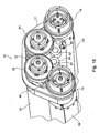
- a common drive motor 88 is provided which via a gear 89, for example a drive pinion 89 drives a gear 91, which in turn is in engagement with two further gears 92 and 93.
- the gear 91 may also be omitted, so that the drive pinion 89 with the gears 92 and 93 is engaged.
- the gear 92 is in driving connection with the gear 78 of the forme cylinder 03 and the gear 93 with the gear 86 of the forme cylinder 11.
- the gear 93 is formed as an adjustable double wheel to the position (register) of the two double printing units 13; 14 to adjust.
- the gear 92 may be formed as a clutch for stopping the lower double printing unit 13.
- the drive motor 88 may be a position-controlled and / or speed-controlled drive motor 88 and, in particular, fixed to the device and, in particular, coaxial with the drive pinion 89 or with the gear 91.
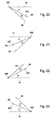
- the angle ⁇ is 28 ° and the angle ⁇ is 13 °.
- the angle ⁇ is 24 ° and the angle ⁇ is 19 °.
- the angle ⁇ is 28 ° and the angle ⁇ is 13 °.
- the angle ⁇ is 24 ° and the angle ⁇ is 19 °.
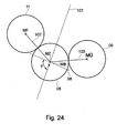
- the arrangement is preferably selected overall so that when adjusting the cylinder position near the pressure-on position, a change in the axial distance of the corresponding transfer cylinder, z. B. the transfer cylinder 08 to the adjacent transfer cylinder, z. B. to the transfer cylinder 09 and a change in the axial distance of the corresponding transfer cylinder 08 to the associated form cylinder, z. B. to the forme cylinder 11 in a ratio of at least approximately 1: 1.
- This condition is met in the case of the embodiment described here. This condition will generally be satisfied, for example, especially if, as in Fig.
- the center MZ of the transfer cylinder 08 and the center MB of the corresponding eccentric bushing 19 are at least approximately on a straight line 98 which is perpendicular to an angle bisector 101 between that line 102, which connects the center MZ with the center MF of the associated forme cylinder 11 and that straight line 103 which connects the center MZ with the center MÜ of the adjacent transfer cylinder 09.
- the straight line 98 should preferably include an angle ⁇ between 60 ° and 120 °, in particular an angle ⁇ between 75 ° and 105 °, with the bisector 101.
- the drive motor 49 is not in positive drive connection to another printing unit.
- the two gears 92, 93 are exemplary on the side frame 02 outside of the inserts 17; 18 stored.
Landscapes
- Engineering & Computer Science (AREA)
- Mechanical Engineering (AREA)
- Rotary Presses (AREA)
Description
Die Erfindung betrifft eine Druckeinheit einer Druckmaschine mit zwei übereinander angeordneten Doppeldruckwerken gemäß dem Oberbegriff des Anspruchs 1.The invention relates to a printing unit of a printing machine with two stacked double printing units according to the preamble of claim 1.
Aus der
Aus der
Aus der
In
Die
Der Erfindung liegt die Aufgabe zugrunde, eine Druckeinheit einer Druckmaschine mit zwei übereinander angeordneten Doppeldruckwerken zu schaffen.The invention has for its object to provide a printing unit of a printing machine with two stacked double printing units.
Die Aufgabe wird erfindungsgemäß durch die Merkmale des Anspruchs 1 gelöst.The object is achieved by the features of claim 1.
Die mit der Erfindung erzielbaren Vorteile bestehen insbesondere darin, dass eine besonders raumsparende Anordnung mit vergleichsweise einfachem Aufbau, einfacher Bedienung und hoher Lagersteifigkeit realisiert werden kann.The achievable with the present invention consist in particular that a particularly space-saving arrangement can be realized with a comparatively simple structure, ease of use and high bearing stiffness.
Ausführungsbeispiele der Erfindung sind in den Zeichnungen dargestellt und werden im Folgenden näher beschrieben.Embodiments of the invention are illustrated in the drawings and will be described in more detail below.
Es zeigen:
- Fig. 1
- eine Ansicht einer H-Druckeinheit nach der Erfindung;
- Fig. 2
- eine Ansicht einer Brückendruckeinheit einer H-Druckeinheit in einer Blickrichtung quer zur Ansicht nach
Fig. 1 , samt Seitengestell und zusätzlicher seitlicher Trägerplatten; - Fig. 3
- eine perspektivische Ansicht der Brückendruckeinheit nach
Fig. 2 ; - Fig. 4
- eine perspektivische Ansicht der Lagerung jeweils eines Endes zweier Zylinder in einem Einsatz;
- Fig. 5
- eine andere perspektivische Ansicht der Lagerung nach
Fig. 4 ; - Fig. 6
- eine Draufsicht auf die Lagerung nach
Fig. 4 ; - Fig. 7
- eine Schnittansicht VII - VII der Lagerung gemäß
Fig. 6 ; - Fig. 8
- eine Seitenansicht eines 3-Ring-Exzenterlagers zur Verwendung in einer Druckeinheit nach
Fig. 2 oder3 oder in einer Lagerung nachFig. 4 bis 7 ; - Fig. 9
- eine Schnittansicht IX-IX des 3-Ring-Exzenterlagers nach
Fig. 8 ; - Fig. 10
- eine Schnittansicht X-X des 3-Ring-Exzenterlagers nach
Fig. 8 ; - Fig. 11
- eine Schnittansicht XI-XI des 3-Ring-Exzenterlagers nach
Fig. 8 ; - Fig. 12
- eine perspektivische Ansicht des 3-Ring-Exzenterlagers gemäß
Fig. 9 von rechts; - Fig. 13
- eine perspektivische Ansicht des 3-Ring-Exzenterlagers gemäß
Fig. 9 von links; - Fig. 14
- eine perspektivische Darstellung des linken Endes der Brückendruckeinheit nach
Fig. 2 , mit zusätzlichen Teilen einer Exzenter-Betätigungsvorrichtung; - Fig. 15
- eine perspektivische Darstellung des rechten Endes der Brückendruckeinheit nach
Fig. 2 , mit zusätzlichen Teilen einer Exzenter-Betätigungsvorrichtung und Antriebsrädern; - Fig. 16
- eine Schnittansicht eines rechten Endes einer Druckeinheit samt Seitengestell und zusätzlicher Trägerplatte;
- Fig. 17
- eine Schnittansicht eines linken Endes eines Zylinders einer Druckeinheit samt Seitengestell und zusätzlicher Trägerplatte;
- Fig. 18
- ein Walzenschema zum Antrieb der H-Druckeinheit nach
Fig. 1 ; - Fig. 19
- ein Schema, welches die Radfluchten zum Walzenschema nach
Fig. 18 zeigt; - Fig. 20
- eine Skizze betreffend die Exzenterlagern des linken oberen Übertragungszylinders gemäß Walzenschema nach
Fig. 18 ; - Fig. 21
- eine Skizze betreffend die Exzenterlagen des rechten oberen Übertragungszylinders gemäß Walzenschema nach
Fig. 18 ; - Fig. 22
- eine Skizze betreffend die Exzenterlagen des linken unteren Übertragungszylinders gemäß Walzenschema nach
Fig. 18 ; - Fig. 23
- eine Skizze betreffend die Exzenterlagen des rechten unteren Übertragungszylinders gemäß Walzenschema nach
Fig. 18 ; - Fig. 24
- eine Skizze betreffend eine bevorzugte Position des Mittelpunkts eines in Druck-An-Stellung befindlichen Übertragungszylinders relativ zu einer Zylinderanordnung.
- Fig. 1
- a view of an H-printing unit according to the invention;
- Fig. 2
- a view of a bridge printing unit of an H-printing unit in a viewing direction transverse to the view
Fig. 1 , including side frame and additional side support plates; - Fig. 3
- a perspective view of the bridge printing unit after
Fig. 2 ; - Fig. 4
- a perspective view of the storage of each one end of two cylinders in an insert;
- Fig. 5
- another perspective view of the storage after
Fig. 4 ; - Fig. 6
- a top view of the storage after
Fig. 4 ; - Fig. 7
- a sectional view VII - VII of the storage according to
Fig. 6 ; - Fig. 8
- a side view of a 3-ring eccentric bearing for use in a printing unit according to
Fig. 2 or3 or in a storage afterFig. 4 to 7 ; - Fig. 9
- a sectional view IX-IX of the 3-ring eccentric bearing according to
Fig. 8 ; - Fig. 10
- a sectional view XX of the 3-ring eccentric bearing according to
Fig. 8 ; - Fig. 11
- a sectional view XI-XI of the 3-ring eccentric bearing according to
Fig. 8 ; - Fig. 12
- a perspective view of the 3-ring eccentric bearing according to
Fig. 9 from the right; - Fig. 13
- a perspective view of the 3-ring eccentric bearing according to
Fig. 9 from the left; - Fig. 14
- a perspective view of the left end of the bridge printing unit after
Fig. 2 with additional parts of an eccentric actuator; - Fig. 15
- a perspective view of the right end of the bridge printing unit after
Fig. 2 with additional parts of an eccentric actuator and drive wheels; - Fig. 16
- a sectional view of a right end of a printing unit together with side frame and additional support plate;
- Fig. 17
- a sectional view of a left end of a cylinder of a printing unit together with side frame and additional support plate;
- Fig. 18
- a roller scheme for driving the H-pressure unit after
Fig. 1 ; - Fig. 19
- a scheme that the Radfluchten to roll pattern after
Fig. 18 shows; - Fig. 20
- a sketch regarding the eccentric bearings of the left upper transfer cylinder according to the roller diagram
Fig. 18 ; - Fig. 21
- a sketch concerning the Exzenterlagen the right upper transfer cylinder according to the roller diagram
Fig. 18 ; - Fig. 22
- a sketch regarding the Exzenterlagen the left lower transfer cylinder according to the roller diagram
Fig. 18 ; - Fig. 23
- a sketch regarding the Exzenterlagen the right lower transfer cylinder according to the roller diagram
Fig. 18 ; - Fig. 24
- a sketch relating to a preferred position of the center of a pressure-in-position transfer cylinder relative to a cylinder assembly.
Zunächst wird auf
Im Falle des Ausführungsbeispiels sind die Zylinder 03; 04 als Formzylinder 03; 04 und die Zylinder 06; 07 als Übertragungszylinder 06; 07 eines ersten Doppeldruckwerks 13 und die Zylinder 11; 12 als Formzylinder 11; 12 und die Zylinder 08; 09 als Übertragungszylinder 08; 09 eines zweiten Doppeldruckwerks 14 ausgebildet, wobei die Übertragungszylinder 06; 07 bzw. 08; 09 im Druckbetrieb zum beidseitigen Bedrucken einer Bedruckstoffbahn 16, die die Druckeinheit 01 in Transportrichtung E von unten nach oben durchläuft, in an sich bekannter Weise gegeneinander anliegen.In the case of the embodiment, the
Die Formzylinder 03; 04; 11; 12 können als Plattenzylinder 03; 04; 11; 12 und die Übertragungszylinder 06; 07; 08; 09 als Gummizylinder 06; 07; 08; 09 ausgebildet sein. Die Übertragungszylinder 06; 07; 08; 09 sind im Falle des hier beschriebenen Ausführungsbeispiels als Gegendruckzylinder 06; 07; 08; 09 ausgebildet.The
Die Druckwerkszylinder 03; 04; 06; 07 bzw. 11; 12; 08; 09 eines jeden Doppeldruckwerks 13; 14 sind im Falle des Ausführungsbeispiels jeweils in einer in etwa U-förmigen Konstellation bzw., im Falle des untengelegenen Doppeldruckwerks 13, in einer Konstellation entsprechend einem umgekehrten U zur Ausbildung jeweils einer Brückendruckeinheit 13; 14 angeordnet, wobei die beiden Brückendruckeinheiten 13; 14 übereinander liegend angeordnet sind und zusammen eine H-Druckeinheit 01 definieren. Jedem Druckwerk einer jeden Brückendruckeinheit 13; 14 sind in nicht näher dargestellter Weise die üblichen peripheren Einheiten wie Farbwerk, Feuchtwerk o. dgl. zugeordnet.The
Die Zylinder 03; 04; 06; 07 bzw. 08; 09; 11; 12 einer jeden Brückendruckeinheit 13; 14 sind beidseitig jeweils an bzw. in einem Einsatz 17 bzw. 18 gelagert, der jeweils lösbar am Seitengestell 02 fixiert ist. Die Einsätze 17; 18 werden auch Glocken 17; 18 genannt. Die Lagerung der Zylinder 03; 04; 06; 07 an den beiderseitig vorgesehenen Einsätzen 17 der Brückendruckeinheit 13 wird insbesondere auch aus
Zumindest die Übertragungszylinder 06; 07; 08; 09 sind jeweils zumindest zwischen einer Druck-An-Position, in der sie an der Bedruckstoffbahn 16 bzw. dem jeweils gegenüberliegenden Übertragungszylinder 06; 07; 08; 09 anliegen, und einer Druck-Ab-Position, in der sie von der Bedruckstoffbahn 16 bzw. dem jeweils gegenüberliegenden Übertragungszylinder 06; 07; 08; 09 abgestellt sind, beweglich angeordnet.At least the
Im Falle einer bevorzugten Ausführungsform der Erfindung sind sämtliche Formzylinder 03; 04; 11; 12 der H-Druckeinheit 01 bzgl. ihrer jeweiligen axialen Lage am jeweiligen Einsatz 17 bzw. 18 fest angeordnet, d. h. es ist keinerlei Verstellmöglichkeit der Formzylinder 03; 04; 11; 12 in einer Richtung senkrecht zu ihrer Achse vorgesehen, während sämtliche Übertragungszylinder 06; 07; 08; 09 bzgl. ihrer axialen Lage zum jeweiligen Einsatz 17 bzw. 18 verstellbar angeordnet sind, insbesondere mittels jeweils eines Lagers 19, z. B. einer Exzentereinrichtung 19, die jeweils von einer Exzenterbuchse 19, z. B. einem Exzenterlager 19, insbesondere von einem 3-Ring-Exzenterlager 19 gebildet sein kann, wie dieses im Folgenden im Zusammenhang mit
Der Einsatz 17, der in hier nicht näher dargestellter Weise in einer entsprechenden Ausnehmung des Seitengestells 02 der Druckmaschine aufgenommen ist und über seinen umlaufenden Kragen 21 mittels geeigneter Befestigungsmittel am Seitengestell 02 fixierbar ist, weist zwei sich in axialer Richtung der Zylinder 03; 06 erstreckende Durchgangsbohrungen 22; 23 auf, durch die hindurch sich die Zapfen 24; 26 der Zylinder 03; 06 erstrecken. In jeder Durchgangsbohrung 22; 23 ist ein Lager 19; 27 angeordnet, über das der jeweilige Zapfen 24 bzw. 26 am Einsatz 17 und hierüber am Seitengestell 02 der Druckmaschine zur Rotation des Formzylinders 03 bzw. des Übertragungszylinders 06 um seine jeweilige Achse gelagert ist.The
Das Lager 27 zur Lagerung des Formzylinders 03 ist als Wälzlager 27 ausgebildet. Im Einzelnen ist das Lager 27 als Zylinderrollenlager 27 mit kegeligem Innenring ausgebildet, dessen Form der kegeligen Form des entsprechenden, gegenüberliegenden Abschnitts des Zapfens 24 entspricht, so dass durch Verschieben des Innenrings des Lagers 27 in axialer Richtung das Lagerspiel eingestellt werden kann. Mit der Bezugsziffer 33 ist ein Abdeckblech 33 bezeichnet, welches das Lager 27 an der Innenseite 31 des Einsatzes 17 abdeckt.The bearing 27 for mounting the
Die axiale Länge I4 des Lagers 27 ist deutlich kleiner als die in Axialrichtung gemessene Dicke bzw. axiale Länge I5 der Einsatzes 17 bzw. der Glocke 17, im Falle des Ausführungsbeispiels weniger als die Hälfte der Dicke I5 des Einsatzes 17. Des Weiteren ist die Dicke D1 des Seitengestells 02 wesentlich geringer als die Dicke I5 des Einsatzes 17. Der Einsatz 17 ist mit seiner dem Ballen 28 des Zylinders 03 abgewandten, den Kragen 21 aufweisenden Seite im bzw. am Seitengestell 02 befestigt. Demgegenüber ist das Lager 27 in der Durchgangsbohrung 22 im Wesentlichen bündig mit der dem Ballen 28 zugewandten Innenseite 31 des Einsatzes angeordnet, wodurch sich eine hohe Lagersteifigkeit ergibt.The axial length I4 of the
Auf dem Zapfen 24 des Formzylinders 03 ist eine sich durch den Einsatz 17 hindurch erstreckende Buchse 32 in axialer Richtung verschieblich angeordnet. Eine erste, dem Ballen 28 des Formzylinders 03 zugewandte Stirnfläche der Buchse 32 wirkt auf den Innenring des Lagers 27. Auf eine zweite, dem Ballen 28 des Formzylinders 03 abgewandte Stirnfläche der Buchse 32 wirkt eine hier nicht näher dargestellte Einstelleinrichtung bzw. ein Verstellmechanismus für die axiale Einstellung bzw. Verstellung des Zylinders 03 relativ zum Einsatz 17 und somit relativ zum Seitengestell 02.On the
Darüber hinaus kann die Buchse 32 mit einem Antriebsmittel, z. B. einem Zahnrad zum Antrieb des Zylinders 03 versehen sein. Ggf. kann auch ein zweites Zahnrad zum Antrieb eines Farb- und/oder Feuchtwerks vorgesehen sein.In addition, the
Das Lager 19 zur Lagerung des Übertragungszylinders 06 ist als 3-Ring-Exzenterlager 19 ausgebildet. Die axiale Länge I3 des Lagers 19 entspricht in etwa derjenigen des Lagers 27 und ist ebenfalls deutlich kleiner als die in Axialrichtung gemessene Dicke I5 des Einsatzes 17 bzw. der Glocke 17, im Falle des Ausführungsbeispiels also weniger als die Hälfte der Dicke I5 des Einsatzes 17. Das Lager 19 ist in der Durchgangsbohrung 23 wiederum im Wesentlichen bündig mit der dem Ballen 29 des Übertragungszylinders 06 bzw. dem Ballen 28 des Formzylinders 03 zugewandten Innenseite 31 des Einsatzes 17 angeordnet, wodurch sich wiederum eine hohe Lagersteifigkeit ergibt.The bearing 19 for mounting the
Das 3-Ring-Exzenterlager 19 weist einen Innenring 34, einen Außenring 36 sowie einen zwischen Innenring 34 und Außenring 36 angeordneten Exzenterring 37 auf. Zwischen dem Innenring 34 und dem Exzenterring 37 einerseits und zwischen dem Exzenterring 37 und dem Außenring 36 andererseits sind jeweils als Zylinderrollenlager ausgebildete Wälzlager vorgesehen. Mittels eines Sicherungsringes 38 wird der Innenring 34 in Position gehalten.The 3-ring
Die innenliegende Fläche des Innenrings 34 ist wiederum kegelig ausgebildet entsprechend der kegeligen Form des entsprechenden, gegenüberliegenden Abschnitts des Zapfens 26 des Zylinders 06.The inner surface of the
Die Bohrung 39, z. B. Lagerbohrung 39 des Exzenterrings 37 zur Aufnahme des Innenrings 34 und des Sicherungsrings 38 ist exzentrisch ausgebildet, so dass die Rotationsachse 41 des Zapfens 26 und somit des Übertragungszylinders 06 exzentrisch zur Achse 40 der Durchgangsbohrung 23 im Einsatz 17 und somit im Seitengestell 02 gelagert ist. Durch Drehen bzw. Verschwenken des Exzenterrings 37 kann die räumliche Lage der Rotationsachse 41 relativ zum Einsatz 17 bzw. zum Seitengestell 02 variiert werden, wodurch es möglich ist, den Übertragungszylinder 06 vom Formzylinder 03 abzustellen bzw. an diesen anzustellen. Zur Winkelverstellung des Exzenterrings 37 ist dieser mit einer hier nicht gezeigten Verstelleinrichtung koppelbar, beispielsweise über einen in eine Bohrung 42 eingesetzten Bolzen.The
Wie aus
An der anderen, gegenüberliegenden Seite der Druckeinheit 01 stehen die entsprechenden Zapfen 24; 26 der Druckwerkszylinder 03; 04; 06; 07 jedoch nicht vor, wie insbesondere aus
Die Exzenter-Betätigungsvorrichtung 43 umfasst einen Antrieb 49 und einen um eine Schwenkachse 44 schwenkbar gelagerten Schwenkhebel 46 mit einem ersten Hebelarm 47, der mit dem Exzenterring 37 des 3-Ring-Exzenterlagers 19 antriebsmäßig verbunden ist, und mit einem zweiten Hebelarm 48, der mit dem Antrieb 49, z. B. Antriebsmotor 49, beispielsweise einem Fluidantrieb 49 mit einer Zylinder-Kolben-Anordnung 49, verbunden ist. Am zweiten Hebelarm 48 ist ein Anschlagsarm 51 ausgebildet, der sich in Richtung zur Mittelebene der Druckeinheit 13 hin erstreckt und anschlagsmäßig mit einem zentralen Anschlagsblock 52 zusammenarbeitet, der für beide Exzenter-Betätigungsvorrichtungen 43 bzw. deren beiden Anschlagsarme 51 einen justierbaren Anschlag, beispielsweise für eine exakte Druck-An-Position der Übertragungszylinder 06, definiert. Die Anschlagsposition ist mittels im Anschlagsblock 52 aufgenommener Justierschrauben 53 justierbar.The
Der Schwenkhebel 46 weist einen im Falle des Ausführungsbeispiels teilzylindrisch ausgebildeten, sich in axialer Richtung von außen in die Durchgangsbohrung 23 des Einsatzes 17 hinein erstreckenden Kopplungsabschnitt 54 auf, über den eine Schwenkbewegung des Schwenkhebels 46 auf den Exzenterring 37 dahingehend übertragen wird, dass der Exzenterring 37 um einen entsprechenden Betrag gedreht und somit der zugeordnete Übertragungszylinder 06 um einen entsprechenden Betrag verschwenkt wird.The
Um beide Enden des Übertragungszylinders 06 synchron zu verschwenken, ist für jede Exzenter-Betätigungsvorrichtung 43 jeweils eine Synchronisationseinrichtung 56 vorgesehen, vgl. auch
Zumindest die Exzenter-Betätigungsvorrichtungen 43 der in
Ein Träger 69 in Form einer Trägerplatte 69 ist vom Seitengestell 02 nach außen beabstandet angeordnet und beispielsweise mittels Bolzen 71 am Seitengestell 02 lösbar fixiert, vgl. auch
Die Abmessungen der Bauteile der Druckeinheit 13 sind so gewählt, dass sich im Zusammenhang mit der gewählten Anordnung der Bauteile bei insgesamt vergleichsweise kompakter Abmessungen ein zuverlässiger und stabiler Betrieb ergibt, insbesondere, eine hohe Steifigkeit der Lagerung der Zylinder 03; 04; 06; 07, wodurch die Druckqualität gesteigert wird. Im Einzelnen werden folgende Abmessungen bzw. Größenverhältnisse bevorzugt verwendet:The dimensions of the components of the
Bei einer Bahnbreite I1 der Bedruckstoffbahn 16 von vorzugsweise 1.000 mm +/- 10 % ergibt sich eine axiale Länge 12 der Ballen 28; 29 der Zylinder 03; 04; 06; 07 von vorzugsweise 950 mm bis 1.250 mm, insbesondere von 1.000 mm bis 1.200 mm, beispielsweise von 1.110 mm +/- 5 %. Der Durchmesser d2 eines jeden Zapfens 24; 26 der Zylinder 03; 04; 06; 07 beträgt vorzugsweise 55 mm bis 75 mm, insbesondere 60 mm bis 70 mm, beispielsweise 65 mm +/- 5 %.With a web width I1 of the
Der Durchmesser d3 eines jeden Ballens 28; 28 der Zylinder 03; 04; 06; 07 variiert in der Regel je nach Anwendungsfall und kann beispielsweise 150 mm bis 250 mm, insbesondere 169 mm bis 222 mm +/- 5 % oder 195 mm +/- 15 % betragen.The diameter d3 of each
Das 3-Ring-Exzenterlager 19 des Übertragungszylinders 06 bzw. 07 kann einen Außendurchmesser d4 von vorzugsweise 130 mm bis 190 mm, insbesondere von 145 mm bis 175 mm, beispielsweise von 160 mm +/- 5 % aufweisen, sowie einen Innendurchmesser d5 entsprechend dem Durchmesser d2 der Zapfen 24; 26, also vorzugsweise 55 mm bis 75 mm, insbesondere 60 mm bis 70 mm, beispielsweise 65 mm +/- 5 %. Die Exzentrizität e des 3-Ring-Exzenterlagers 19 kann vorzugsweise 8 mm bis 24 mm, insbesondere von 12 mm bis 20 mm, beispielsweise von 16 mm +/- 10 % betragen; des Weiteren kann die Exzentrizität e des 3-Ring-Exzenterlagers 19 vorzugsweise 1/10 +/- 50 %, insbesondere 1/10 +/- 25 %, beispielsweise 1/10 +/- 10 % des Außendurchmessers d4 des 3-Ring-Exzenterlagers 19 betragen. Die axiale Länge 13 des 3-Ring-Exzenterlagers 19 kann vorzugsweise 40 mm bis 70 mm, insbesondere 50 mm bis 62 mm, beispielsweise 56 mm +/- 5 % betragen.The 3-ring
Das Lager 27 des Formzylinders 03 bzw. 04 kann eine Außendurchmesser d6 von vorzugsweise 80 mm bis 120 mm, insbesondere von 90 mm bis 110 mm, beispielsweise von 100 mm +/- 5 % aufweisen, sowie einen Innendurchmesser d7 entsprechend dem Durchmesser d2 der Zapfen 24; 26, also vorzugsweise 55 mm bis 75 mm, insbesondere 60 mm bis 70 mm, beispielsweise 65 mm +/- 5 %. Die axiale Länge I4 des Lagers 27 kann vorzugsweise 35 mm bis 65 mm, insbesondere 45 mm bis 55 mm, beispielsweise 50 mm +/- 5 % betragen.The bearing 27 of the
Das Seitengestell 02 bzw., genau gesprochen, die zu beiden Seiten der Druckeinheit 01 bzw. 13 angeordneten Gestellplatten 02 können eine Dicke D1 von 30 mm bis 100 mm, vorzugsweise von 40 mm bis 80 mm, beispielsweise von 60 mm +/- 10 % aufweisen. Die Trägerplatten 61; 69 können demgegenüber entsprechend der schwächeren Belastung etwas geringer dimensioniert werden, vorzugsweise mit einer Dicke D2 von jeweils 25 mm bis 55 mm, insbesondere von 35 mm bis 45 mm, beispielsweise von 40 mm +/- 5 %.The
An der z. B. in
Die an beiden Seiten des Druckwerks 01 angeordneten Gestellplatten 02 des Seitengestells 02 sind mit einem Abstand a3 (lichte Weite) von vorzugsweise 1.000 mm bis 1.500 mm, insbesondere 1.150 mm bis 1.400 mm, beispielsweise 1.280 mm +/- 5 % beabstandet, der Abstand a4 der zueinander gewandten Seiten des Ballens 28 bzw. 29 und der benachbarten Gestellplatte 02 beträgt vorzugsweise 70 mm bis 100 mm, Insbesondere 75 mm bis 95 mm, beispielsweise 85 mm +/- 5 %.The arranged on both sides of the
Ein bevorzugter Abstand a6 (lichte Weite) zwischen der einem Ballen 28; 29 zugeordneten Innenseite eines Seitengestells 02 und der dem Ballen 28; 29 zugeordneten Innenseite 31 eines hierin gehaltenen Einsatzes 17 kann vorzugsweise 60 mm bis 100 mm, insbesondere 70 mm bis 90 mm, beispielsweise 80 mm +/- 10 % betragen.A preferred distance a6 (clear width) between a
Des Weiteren kann die axiale Länge 15 des Einsatzes 17 vorzugsweise 80 mm bis 150 mm, insbesondere 100 mm bis 135 mm, beispielsweise 120 mm +/- 10 % betragen.Furthermore, the
Soweit im Vorstehenden die Maße als beispielsweise angegeben sind, handelt es sich um die Maße des dargestellten bevorzugten Ausführungsbeispiels.Insofar as the measures are given in the foregoing as, for example, are the dimensions of the illustrated preferred embodiment.
Aus dem Vorstehenden ergibt sich insbesondere, dass die Lager 27; 19 sehr nahe am jeweiligen Ballen 28; 29 des zugeordneten Zylinders 03; 06 angeordnet sein können, wodurch sich u.a. die angesprochene hohe Lagersteifigkeit ergibt. Der Abstand a5 zwischen den einander zugewandten Seiten des Ballens 28; 29 und des zugeordneten Lagers 19; 27 kann vorzugsweise 5 mm bis 20 mm, insbesondere 7,5 mm bis 15 mm, beispielsweise wie dargestellt 10 mm +/- 10 % betragen.From the above it follows in particular that the
Demzufolge kann ein bevorzugter Bereich des Verhältnisses von axialer Länge I2 eines Ballens 28; 28 zum Abstand a5 zwischen Ballen 28; 29 und Lager 27; 19 im Bereich zwischen 50 und 250, insbesondere im Bereich zwischen 75 und 150 liegen.As a result, a preferred range of the ratio of axial length I2 of a
Des Weiteren kann ein bevorzugter Bereich des Verhältnisses von Durchmesser d3 eines Ballens 28; 29 zum Abstand a5 zwischen Ballen 28; 29 und Lager 27; 19 im Bereich zwischen 8 und 40 liegen.Furthermore, a preferable range of the ratio of diameter d3 of a
Des Weiteren kann ein bevorzugter Bereich des Verhältnisses von einer axialen Länge 12 des Ballens 28; 29 zum Durchmesser d3 des Ballen 28; 29 zwischen 4,3 und 7,4 liegen, insbesondere zwischen 5 und 6,5.Furthermore, a preferred range of the ratio of an
Es wird nun anhand der
In
Aus den
Im Falle des Übertragungszylinders 08 gemäß
Die Anordnung ist insgesamt vorzugsweise so gewählt, dass bei einem Verstellen der Zylinderposition nahe der Druck-An-Stellung eine Änderung des Achsabstandes des entsprechenden Übertragungszylinders, z. B. des Übertragungszylinders 08 zum benachbarten Übertragungszylinder, z. B. zum Übertragungszylinder 09 und eine Änderung des Achsabstandes des entsprechenden Übertragungszylinders 08 zum zugeordneten Formzylinder, z. B. zum Formzylinder 11 in einem Verhältnis von zumindest annäherungsweise 1:1 erfolgt. Diese Bedingung ist im Falle des hier beschriebenen Ausführungsbeispiels erfüllt. Diese Bedingung wird allgemein beispielsweise insbesondere auch dann erfüllt sein, wenn, wie in
Vorzugsweise steht der Antriebsmotor 49 nicht in formschlüssiger Antriebsverbindung zu einer anderen Druckeinheit. Vorteilhaft ist eine Montage des Antriebsmotors 49 außerhalb der Einsätze 17; 18, wobei der Antriebsmotor 49 in bevorzugter Weise am Seitengestell 02 befestigt ist.Preferably, the
Die beiden Zahnräder 92, 93 sind beispielhaft am Seitengestell 02 außerhalb der Einsätze 17; 18 gelagert.The two gears 92, 93 are exemplary on the
Die Ausführung über das Doppeldruckwerk 13 gelten im Wesentlichen auch für das Doppeldruckwerk 14.The execution of the
- 0101
- Druckeinheit, H-DruckeinheitPrinting unit, H printing unit
- 0202
- Seitengestell, GestellplattenSide frame, frame plates
- 0303
- Zylinder, Druckwerkszylinder, Formzylinder, PlattenzylinderCylinder, printing cylinder, forme cylinder, plate cylinder
- 0404
- Zylinder, Druckwerkszylinder, Formzylinder, PlattenzylinderCylinder, printing cylinder, forme cylinder, plate cylinder
- 0505
- --
- 0606
- Zylinder, Druckwerkszylinder, Übertragungszylinder, Gummizylinder, GegendruckzylinderCylinder, printing cylinder, transfer cylinder, rubber cylinder, impression cylinder
- 0707
- Zylinder, Druckwerkszylinder, Übertragungszylinder, Gummizylinder, GegendruckzylinderCylinder, printing cylinder, transfer cylinder, rubber cylinder, impression cylinder
- 0808
- Zylinder, Druckwerkszylinder, Übertragungszylinder, Gummizylinder, GegendruckzylinderCylinder, printing cylinder, transfer cylinder, rubber cylinder, impression cylinder
- 0909
- Zylinder, Druckwerkszylinder, Übertragungszylinder, Gummizylinder, GegendruckzylinderCylinder, printing cylinder, transfer cylinder, rubber cylinder, impression cylinder
- 1010
- --
- 1111
- Zylinder, Druckwerkszylinder, Formzylinder, PlattenzylinderCylinder, printing cylinder, forme cylinder, plate cylinder
- 1212
- Zylinder, Druckwerkszylinder, Formzylinder, PlattenzylinderCylinder, printing cylinder, forme cylinder, plate cylinder
- 1313
- Doppeldruckwerk, BrückendruckeinheitDouble printing unit, bridge printing unit
- 1414
- Doppeldruckwerk, BrückendruckeinheitDouble printing unit, bridge printing unit
- 1515
- --
- 1616
- Bedruckstoffbahnprinting material
- 1717
- Einsatz, GlockeInsert, bell
- 1818
- Einsatz, GlockeInsert, bell
- 1919
- Lager, Exzentereinrichtung, Exzenterbuchse, Exzenterlager, 3-Ring-ExzenterlagerBearing, eccentric, eccentric, eccentric, 3-ring eccentric
- 2020
- --
- 2121
- Kragen (17; 18)Collar (17; 18)
- 2222
- DurchgangsbohrungThrough Hole
- 2323
- DurchgangsbohrungThrough Hole
- 2424
- Zapfen (03)Cones (03)
- 2525
- --
- 2626
- Zapfen (06)Cones (06)
- 2727
- Lager, Wälzlager, ZylinderrollenlagerBearings, roller bearings, cylindrical roller bearings
- 2828
- Ballen (03)Bales (03)
- 2929
- Ballen (06)Bales (06)
- 3030
- --
- 3131
- Innenseite (17)Inside (17)
- 3232
- BuchseRifle
- 3333
- AbdeckblechCover plate
- 3434
- Innenringinner ring
- 3535
- --
- 3636
- Außenringouter ring
- 3737
- Exzenterringeccentric
- 3838
- Sicherungsringcirclip
- 3939
- Bohrung, Lagerbohrung (37)Bore, bearing bore (37)
- 4040
- Achse (23)Axis (23)
- 4141
- Rotationsachse (26)Rotation axis (26)
- 4242
- Bohrung (37)Bore (37)
- 4343
- Exzenter-BetätigungsvorrichtungEccentric actuating device
- 4444
- Schwenkachse (43)Swivel axis (43)
- 4545
- Außenseite (17)Outside (17)
- 4646
- Schwenkhebel (43)Swing lever (43)
- 4747
- Hebelarm (46)Lever arm (46)
- 4848
- Hebelarm (46)Lever arm (46)
- 4949
- Antrieb, Antriebsmotor, Fluidantrieb, Zylinder-Kolben-AnordnungDrive, drive motor, fluid drive, cylinder-piston arrangement
- 5050
- --
- 5151
- Anschlagsarm (46)Stop arm (46)
- 5252
- Anschlagsblockstop block
- 5353
- Justierschraube (52)Adjustment screw (52)
- 5454
- Kupplungsabschnitt (46)Coupling section (46)
- 5555
- --
- 5656
- Synchronisationseinrichtungsynchronizer
- 5757
- Spindel (56)Spindle (56)
- 5858
- Schwenkarm (56)Swing arm (56)
- 5959
- Schubstange, Koppel (56)Push Rod, Coupling (56)
- 6060
- --
- 6161
- Träger, TrägerplatteCarrier, carrier plate
- 6262
- Bolzenbolt
- 6363
- BuchseRifle
- 6464
- BuchseRifle
- 6565
- --
- 6666
- Einstelleinrichtung, ScheibeAdjustment device, disc
- 6767
- Einstelleinrichtung, ScheibeAdjustment device, disc
- 6868
- Distanzelementspacer
- 6969
- Träger, TrägerplatteCarrier, carrier plate
- 7070
- --
- 7171
- Bolzenbolt
- 7272
- UmfangsregistereinrichtungCircumferential register device
- 7373
- Axiallagereinrichtungaxial bearing
- 7474
- SeitenregistereinrichtungLateral register device
- 7575
- --
- 7676
- ZapfenverlängerungZapf extension
- 7777
- Exzenterlagereccentric
- 7878
- Zahnradgear
- 7979
- Zahnradgear
- 8080
- --
- 8181
- Zahnradgear
- 8282
- Zahnradgear
- 8383
- Zahnradgear
- 8484
- Zahnradgear
- 8585
- --
- 8686
- Zahnradgear
- 8787
- Zahnradgear
- 8888
- Antriebsmotordrive motor
- 8989
- Zahnrad, AntriebsritzelGear, drive pinion
- 9090
- --
- 9191
- Zahnradgear
- 9292
- Zahnradgear
- 9393
- Zahnradgear
- 9494
- Zwischenzahnradintermediate gear
- 9595
- --
- 9696
- Zwischenzahnradintermediate gear
- 9797
- Zwischenzahnradintermediate gear
- 9898
- GeradeJust
- 9999
- GeradeJust
- 100100
- --
- 101101
- Winkelhalbierendebisecting
- 102102
- GeradeJust
- 103103
- GeradeJust
- Ee
- Transportrichtung (16)Transport direction (16)
- HH
- Horizontalehorizontal
- ee
- Exzentrizität (19)Eccentricity (19)
- D1D1
- Dicke (02)Thickness (02)
- D2D2
- Dicke (61; 69)Thickness (61; 69)
- MBMB
- Mittelpunkt (19)Center point (19)
- MFMF
- Mittelpunkt (03; 04; 11; 12)Center point (03; 04; 11; 12)
- MÜMT
- Mittelpunkt (06; 07; 08; 09)Center point (06; 07; 08; 09)
- MZMZ
- Mittelpunkt (06; 07; 08; 09)Center point (06; 07; 08; 09)
- a1a1
- Abstanddistance
- a2a2
- Abstanddistance
- a3a3
- Abstanddistance
- a4a4
- Abstanddistance
- a5a5
- Abstanddistance
- a6a6
- Abstand, InnenseiteDistance, inside
- d2d2
- Durchmesser (24; 26)Diameter (24; 26)
- d3d3
- Durchmesser (28; 29)Diameter (28; 29)
- d4d4
- Außendurchmesser (19)Outer diameter (19)
- d5d5
- Innendurchmesser (19)Inner diameter (19)
- d6d6
- Außendurchmesser (27)Outer diameter (27)
- d7d7
- Innendurchmesser (27)Inner diameter (27)
- 1111
- Bahnbreite (16)Web width (16)
- 1212
- Länge, axial (28; 29)Length, axial (28; 29)
- 1313
- Länge, axial (19)Length, axial (19)
- 1414
- Länge, axial (27)Length, axial (27)
- 1515
- Länge, axial, Dicke (17)Length, axial, thickness (17)
- αα
- Winkelangle
- ββ
- Winkelangle
- γγ
- Winkelangle
Claims (8)
- Printing unit of a printing press with two double printing groups (13; 14) arranged one above the other, each double printing group (13; 14) having two form cylinders (03; 04 or 11; 12) and two transfer cylinders (06; 07; or 08; 09), the front journals (24; 26) of the form cylinder (03; 04 or 11; 12) and the transfer cylinder (06; 07; or 08; 09) of a double printing group (13; 14) in each case being supported on both sides on an insert (17; 18), which for its part is arranged detachably on the and/or in the side frame (02) of the printing press, characterized in that the four form cylinders (03; 04; 11; 12) and the four transfer cylinders (06; 07; 08; 09) of the printing unit (01) can be driven by means of a sole common drive motor (49), in that each of the two double printing groups (13; 14) is driven by a gear wheel (93; 92), in that each of the two gear wheels (93; 92) is in each case in engagement with a gear wheel (78; 86) arranged on a form cylinder (03; 04; 11; 12), in that the two gear wheels (92; 93) are in engagement with a common gear wheel (91) or drive pinion (89), in that the drive motor (88) is arranged driving the gear wheel (91) or drive pinion (89), and in that the gear wheel (93) situated in engagement with the gear wheel situated in engagement with the gear wheel (78) arranged on the form cylinder (03) of the upper double printing group (14) is designed as an adjustable double-tooth group in order to adjust the position of the two double printing groups (13; 14).
- Printing unit according to Claim 1, characterized in that the gear wheel (92) situated in engagement with the gear wheel (78) arranged on the form cylinder (03) of the lower double printing group (13) is designed as a coupling for the stopping of the lower double printing group (13).
- Printing unit according to Claim 1, characterized in that the drive motor (88) is arranged co-axially to the gear wheel (91) or drive pinion (89).
- Printing unit according to Claim 1, characterized in that the printing unit (01) has two inserts (17; 18).
- Printing unit according to Claim 1, characterized in that the drive motor (49) is connected drivewise with in each case one form cylinder (03; 04 or 11; 12) in each case of a double printing group (13; 14).
- Printing unit according to Claim 1, characterized in that the drive motor (49) is not in positive drive connection to another printing unit.
- Printing unit according to Claim 1, characterized in that the drive motor (49) is fixed to the side frame (02) outside of the inserts (17; 18).
- Printing unit according to Claim 1, characterized in that the two gear wheels (92; 93) are supported on the side frame (02) outside the inserts (17; 18).
Applications Claiming Priority (1)
| Application Number | Priority Date | Filing Date | Title |
|---|---|---|---|
| DE200610054381 DE102006054381A1 (en) | 2006-11-17 | 2006-11-17 | Printing unit of a printing machine with two stacked double printing units |
Publications (3)
| Publication Number | Publication Date |
|---|---|
| EP1923213A2 EP1923213A2 (en) | 2008-05-21 |
| EP1923213A3 EP1923213A3 (en) | 2011-01-26 |
| EP1923213B1 true EP1923213B1 (en) | 2012-11-14 |
Family
ID=39145413
Family Applications (1)
| Application Number | Title | Priority Date | Filing Date |
|---|---|---|---|
| EP20070114643 Not-in-force EP1923213B1 (en) | 2006-11-17 | 2007-08-21 | Printing unit of a printing press with two double printing groups arranged over each other |
Country Status (2)
| Country | Link |
|---|---|
| EP (1) | EP1923213B1 (en) |
| DE (1) | DE102006054381A1 (en) |
Families Citing this family (1)
| Publication number | Priority date | Publication date | Assignee | Title |
|---|---|---|---|---|
| DE102011089197A1 (en) * | 2011-12-20 | 2013-06-20 | Koenig & Bauer Aktiengesellschaft | Side frame of a printing machine |
Family Cites Families (5)
| Publication number | Priority date | Publication date | Assignee | Title |
|---|---|---|---|---|
| DE4430693B4 (en) * | 1994-08-30 | 2005-12-22 | Man Roland Druckmaschinen Ag | Drives for a web-fed rotary offset printing machine |
| US7216585B2 (en) * | 2001-01-24 | 2007-05-15 | Goss International Americas, Inc. | Shaftless motor drive for a printing press with an anilox inker |
| DE10129762B4 (en) * | 2001-06-20 | 2004-07-29 | Koenig & Bauer Ag | printing unit |
| CN1781703A (en) * | 2001-08-03 | 2006-06-07 | 柯尼格及包尔公开股份有限公司 | Printing device in printing machine |
| WO2003039872A1 (en) * | 2001-11-08 | 2003-05-15 | Koenig & Bauer Aktiengesellschaft | Drive of a printing group |
-
2006
- 2006-11-17 DE DE200610054381 patent/DE102006054381A1/en not_active Withdrawn
-
2007
- 2007-08-21 EP EP20070114643 patent/EP1923213B1/en not_active Not-in-force
Also Published As
| Publication number | Publication date |
|---|---|
| EP1923213A2 (en) | 2008-05-21 |
| DE102006054381A1 (en) | 2008-05-21 |
| EP1923213A3 (en) | 2011-01-26 |
Similar Documents
| Publication | Publication Date | Title |
|---|---|---|
| EP0813959B1 (en) | Driven cylinder | |
| WO2005097505A2 (en) | Printing unit on a web-fed rotary printing press | |
| EP1923214B1 (en) | Printing unit of a printing press with two double printing groups arranged one over the other | |
| WO2005096691B1 (en) | Printing units on a web-fed rotary printing press | |
| DE102007017097B4 (en) | Printing cylinder changing device for printing length variable printing units in a full rotation printing press | |
| EP2523810B1 (en) | Device for bearing one or more cylinders of a printing press | |
| EP1280666B1 (en) | Arrangement for adjusting the interval between the rotational axes of cylinders | |
| EP1923213B1 (en) | Printing unit of a printing press with two double printing groups arranged over each other | |
| DE1241464B (en) | Device on a rotary printing press for inclining the axis of the forme cylinder with respect to that of the printing unit cylinder that interacts with it | |
| DE10046367B4 (en) | Drive a printing unit | |
| DE102006054380B4 (en) | Arrangement in a printing press with at least one plate cylinder and at least one transfer cylinder | |
| DE10014040B4 (en) | Shaft for synchronizing a positioning movement | |
| DE4436584C2 (en) | Plate cylinder storage | |
| EP1042123B1 (en) | Roller | |
| EP2114681B1 (en) | Printing unit of a rotary printing press and a method for washing a dampening unit of a printing unit | |
| EP0353652B1 (en) | Additional device for attachment to an offset-printing machine | |
| DE102007011045B4 (en) | press | |
| DE10331605B3 (en) | Printing press roller supported at either end for adjustment in a radial direction relative to roller longitudinal axis | |
| DE4401289C2 (en) | Cylinder adjustment device | |
| DE10046375B4 (en) | Drive a printing unit | |
| DE102010000891B4 (en) | Devices for the storage of printing cylinders of a printing machine | |
| DE102011082679B4 (en) | Device and method for fastening and / or adjusting a bearing device of a printing cylinder | |
| DE102010030331B4 (en) | Devices for storing one or more cylinders of a printing press | |
| DE102007000831B4 (en) | Roller of a rotary printing press and method for adjusting an applicator roll | |
| DE4139326C2 (en) | Device for setting the circumferential register on rotary printing presses |
Legal Events
| Date | Code | Title | Description |
|---|---|---|---|
| PUAI | Public reference made under article 153(3) epc to a published international application that has entered the european phase |
Free format text: ORIGINAL CODE: 0009012 |
|
| AK | Designated contracting states |
Kind code of ref document: A2 Designated state(s): AT BE BG CH CY CZ DE DK EE ES FI FR GB GR HU IE IS IT LI LT LU LV MC MT NL PL PT RO SE SI SK TR |
|
| AX | Request for extension of the european patent |
Extension state: AL BA HR MK RS |
|
| PUAL | Search report despatched |
Free format text: ORIGINAL CODE: 0009013 |
|
| AK | Designated contracting states |
Kind code of ref document: A3 Designated state(s): AT BE BG CH CY CZ DE DK EE ES FI FR GB GR HU IE IS IT LI LT LU LV MC MT NL PL PT RO SE SI SK TR |
|
| AX | Request for extension of the european patent |
Extension state: AL BA HR MK RS |
|
| 17P | Request for examination filed |
Effective date: 20110121 |
|
| 17Q | First examination report despatched |
Effective date: 20110224 |
|
| AKX | Designation fees paid |
Designated state(s): AT BE BG CH CY CZ DE DK EE ES FI FR GB GR HU IE IS IT LI LT LU LV MC MT NL PL PT RO SE SI SK TR |
|
| GRAP | Despatch of communication of intention to grant a patent |
Free format text: ORIGINAL CODE: EPIDOSNIGR1 |
|
| GRAS | Grant fee paid |
Free format text: ORIGINAL CODE: EPIDOSNIGR3 |
|
| GRAA | (expected) grant |
Free format text: ORIGINAL CODE: 0009210 |
|
| AK | Designated contracting states |
Kind code of ref document: B1 Designated state(s): AT BE BG CH CY CZ DE DK EE ES FI FR GB GR HU IE IS IT LI LT LU LV MC MT NL PL PT RO SE SI SK TR |
|
| REG | Reference to a national code |
Ref country code: GB Ref legal event code: FG4D Free format text: NOT ENGLISH |
|
| REG | Reference to a national code |
Ref country code: CH Ref legal event code: EP Ref country code: AT Ref legal event code: REF Ref document number: 583734 Country of ref document: AT Kind code of ref document: T Effective date: 20121115 |
|
| REG | Reference to a national code |
Ref country code: IE Ref legal event code: FG4D Free format text: LANGUAGE OF EP DOCUMENT: GERMAN |
|
| REG | Reference to a national code |
Ref country code: DE Ref legal event code: R096 Ref document number: 502007010856 Country of ref document: DE Effective date: 20130103 |
|
| REG | Reference to a national code |
Ref country code: NL Ref legal event code: VDEP Effective date: 20121114 |
|
| REG | Reference to a national code |
Ref country code: LT Ref legal event code: MG4D |
|
| PG25 | Lapsed in a contracting state [announced via postgrant information from national office to epo] |
Ref country code: ES Free format text: LAPSE BECAUSE OF FAILURE TO SUBMIT A TRANSLATION OF THE DESCRIPTION OR TO PAY THE FEE WITHIN THE PRESCRIBED TIME-LIMIT Effective date: 20130225 Ref country code: SE Free format text: LAPSE BECAUSE OF FAILURE TO SUBMIT A TRANSLATION OF THE DESCRIPTION OR TO PAY THE FEE WITHIN THE PRESCRIBED TIME-LIMIT Effective date: 20121114 Ref country code: FI Free format text: LAPSE BECAUSE OF FAILURE TO SUBMIT A TRANSLATION OF THE DESCRIPTION OR TO PAY THE FEE WITHIN THE PRESCRIBED TIME-LIMIT Effective date: 20121114 Ref country code: LT Free format text: LAPSE BECAUSE OF FAILURE TO SUBMIT A TRANSLATION OF THE DESCRIPTION OR TO PAY THE FEE WITHIN THE PRESCRIBED TIME-LIMIT Effective date: 20121114 |
|
| PG25 | Lapsed in a contracting state [announced via postgrant information from national office to epo] |
Ref country code: LV Free format text: LAPSE BECAUSE OF FAILURE TO SUBMIT A TRANSLATION OF THE DESCRIPTION OR TO PAY THE FEE WITHIN THE PRESCRIBED TIME-LIMIT Effective date: 20121114 Ref country code: PL Free format text: LAPSE BECAUSE OF FAILURE TO SUBMIT A TRANSLATION OF THE DESCRIPTION OR TO PAY THE FEE WITHIN THE PRESCRIBED TIME-LIMIT Effective date: 20121114 Ref country code: GR Free format text: LAPSE BECAUSE OF FAILURE TO SUBMIT A TRANSLATION OF THE DESCRIPTION OR TO PAY THE FEE WITHIN THE PRESCRIBED TIME-LIMIT Effective date: 20130215 Ref country code: CY Free format text: LAPSE BECAUSE OF FAILURE TO SUBMIT A TRANSLATION OF THE DESCRIPTION OR TO PAY THE FEE WITHIN THE PRESCRIBED TIME-LIMIT Effective date: 20121114 Ref country code: SI Free format text: LAPSE BECAUSE OF FAILURE TO SUBMIT A TRANSLATION OF THE DESCRIPTION OR TO PAY THE FEE WITHIN THE PRESCRIBED TIME-LIMIT Effective date: 20121114 Ref country code: PT Free format text: LAPSE BECAUSE OF FAILURE TO SUBMIT A TRANSLATION OF THE DESCRIPTION OR TO PAY THE FEE WITHIN THE PRESCRIBED TIME-LIMIT Effective date: 20130314 |
|
| PG25 | Lapsed in a contracting state [announced via postgrant information from national office to epo] |
Ref country code: DK Free format text: LAPSE BECAUSE OF FAILURE TO SUBMIT A TRANSLATION OF THE DESCRIPTION OR TO PAY THE FEE WITHIN THE PRESCRIBED TIME-LIMIT Effective date: 20121114 Ref country code: BG Free format text: LAPSE BECAUSE OF FAILURE TO SUBMIT A TRANSLATION OF THE DESCRIPTION OR TO PAY THE FEE WITHIN THE PRESCRIBED TIME-LIMIT Effective date: 20130214 Ref country code: EE Free format text: LAPSE BECAUSE OF FAILURE TO SUBMIT A TRANSLATION OF THE DESCRIPTION OR TO PAY THE FEE WITHIN THE PRESCRIBED TIME-LIMIT Effective date: 20121114 Ref country code: SK Free format text: LAPSE BECAUSE OF FAILURE TO SUBMIT A TRANSLATION OF THE DESCRIPTION OR TO PAY THE FEE WITHIN THE PRESCRIBED TIME-LIMIT Effective date: 20121114 Ref country code: CZ Free format text: LAPSE BECAUSE OF FAILURE TO SUBMIT A TRANSLATION OF THE DESCRIPTION OR TO PAY THE FEE WITHIN THE PRESCRIBED TIME-LIMIT Effective date: 20121114 |
|
| PG25 | Lapsed in a contracting state [announced via postgrant information from national office to epo] |
Ref country code: IT Free format text: LAPSE BECAUSE OF FAILURE TO SUBMIT A TRANSLATION OF THE DESCRIPTION OR TO PAY THE FEE WITHIN THE PRESCRIBED TIME-LIMIT Effective date: 20121114 Ref country code: NL Free format text: LAPSE BECAUSE OF FAILURE TO SUBMIT A TRANSLATION OF THE DESCRIPTION OR TO PAY THE FEE WITHIN THE PRESCRIBED TIME-LIMIT Effective date: 20121114 Ref country code: RO Free format text: LAPSE BECAUSE OF FAILURE TO SUBMIT A TRANSLATION OF THE DESCRIPTION OR TO PAY THE FEE WITHIN THE PRESCRIBED TIME-LIMIT Effective date: 20121114 |
|
| PLBE | No opposition filed within time limit |
Free format text: ORIGINAL CODE: 0009261 |
|
| STAA | Information on the status of an ep patent application or granted ep patent |
Free format text: STATUS: NO OPPOSITION FILED WITHIN TIME LIMIT |
|
| 26N | No opposition filed |
Effective date: 20130815 |
|
| REG | Reference to a national code |
Ref country code: DE Ref legal event code: R097 Ref document number: 502007010856 Country of ref document: DE Effective date: 20130815 |
|
| BERE | Be: lapsed |
Owner name: KOENIG & BAUER A.G. Effective date: 20130831 |
|
| REG | Reference to a national code |
Ref country code: CH Ref legal event code: PL |
|
| GBPC | Gb: european patent ceased through non-payment of renewal fee |
Effective date: 20130821 |
|
| PG25 | Lapsed in a contracting state [announced via postgrant information from national office to epo] |
Ref country code: CH Free format text: LAPSE BECAUSE OF NON-PAYMENT OF DUE FEES Effective date: 20130831 Ref country code: MC Free format text: LAPSE BECAUSE OF FAILURE TO SUBMIT A TRANSLATION OF THE DESCRIPTION OR TO PAY THE FEE WITHIN THE PRESCRIBED TIME-LIMIT Effective date: 20121114 Ref country code: LI Free format text: LAPSE BECAUSE OF NON-PAYMENT OF DUE FEES Effective date: 20130831 |
|
| REG | Reference to a national code |
Ref country code: IE Ref legal event code: MM4A |
|
| REG | Reference to a national code |
Ref country code: FR Ref legal event code: ST Effective date: 20140430 |
|
| PG25 | Lapsed in a contracting state [announced via postgrant information from national office to epo] |
Ref country code: BE Free format text: LAPSE BECAUSE OF NON-PAYMENT OF DUE FEES Effective date: 20130831 |
|
| PG25 | Lapsed in a contracting state [announced via postgrant information from national office to epo] |
Ref country code: IE Free format text: LAPSE BECAUSE OF NON-PAYMENT OF DUE FEES Effective date: 20130821 Ref country code: GB Free format text: LAPSE BECAUSE OF NON-PAYMENT OF DUE FEES Effective date: 20130821 |
|
| PG25 | Lapsed in a contracting state [announced via postgrant information from national office to epo] |
Ref country code: FR Free format text: LAPSE BECAUSE OF NON-PAYMENT OF DUE FEES Effective date: 20130902 |
|
| REG | Reference to a national code |
Ref country code: AT Ref legal event code: MM01 Ref document number: 583734 Country of ref document: AT Kind code of ref document: T Effective date: 20130821 |
|
| PG25 | Lapsed in a contracting state [announced via postgrant information from national office to epo] |
Ref country code: AT Free format text: LAPSE BECAUSE OF NON-PAYMENT OF DUE FEES Effective date: 20130821 |
|
| PG25 | Lapsed in a contracting state [announced via postgrant information from national office to epo] |
Ref country code: MT Free format text: LAPSE BECAUSE OF FAILURE TO SUBMIT A TRANSLATION OF THE DESCRIPTION OR TO PAY THE FEE WITHIN THE PRESCRIBED TIME-LIMIT Effective date: 20121114 Ref country code: TR Free format text: LAPSE BECAUSE OF FAILURE TO SUBMIT A TRANSLATION OF THE DESCRIPTION OR TO PAY THE FEE WITHIN THE PRESCRIBED TIME-LIMIT Effective date: 20121114 |
|
| PG25 | Lapsed in a contracting state [announced via postgrant information from national office to epo] |
Ref country code: LU Free format text: LAPSE BECAUSE OF NON-PAYMENT OF DUE FEES Effective date: 20130821 Ref country code: HU Free format text: LAPSE BECAUSE OF FAILURE TO SUBMIT A TRANSLATION OF THE DESCRIPTION OR TO PAY THE FEE WITHIN THE PRESCRIBED TIME-LIMIT; INVALID AB INITIO Effective date: 20070821 |
|
| REG | Reference to a national code |
Ref country code: DE Ref legal event code: R081 Ref document number: 502007010856 Country of ref document: DE Owner name: KOENIG BAUER AG, DE Free format text: FORMER OWNER: KOENIG BAUER AKTIENGESELLSCHAFT, 97080 WUERZBURG, DE Ref country code: DE Ref legal event code: R081 Ref document number: 502007010856 Country of ref document: DE Owner name: KOENIG & BAUER AG, DE Free format text: FORMER OWNER: KOENIG & BAUER AKTIENGESELLSCHAFT, 97080 WUERZBURG, DE |
|
| PG25 | Lapsed in a contracting state [announced via postgrant information from national office to epo] |
Ref country code: IS Free format text: LAPSE BECAUSE OF FAILURE TO SUBMIT A TRANSLATION OF THE DESCRIPTION OR TO PAY THE FEE WITHIN THE PRESCRIBED TIME-LIMIT Effective date: 20121114 |
|
| PGFP | Annual fee paid to national office [announced via postgrant information from national office to epo] |
Ref country code: DE Payment date: 20180823 Year of fee payment: 12 |
|
| REG | Reference to a national code |
Ref country code: DE Ref legal event code: R119 Ref document number: 502007010856 Country of ref document: DE |
|
| PG25 | Lapsed in a contracting state [announced via postgrant information from national office to epo] |
Ref country code: DE Free format text: LAPSE BECAUSE OF NON-PAYMENT OF DUE FEES Effective date: 20200303 |