EP1923172A1 - Handwerkzeugmaschine mit einer Blockiervorrichtung - Google Patents
Handwerkzeugmaschine mit einer Blockiervorrichtung Download PDFInfo
- Publication number
- EP1923172A1 EP1923172A1 EP07020743A EP07020743A EP1923172A1 EP 1923172 A1 EP1923172 A1 EP 1923172A1 EP 07020743 A EP07020743 A EP 07020743A EP 07020743 A EP07020743 A EP 07020743A EP 1923172 A1 EP1923172 A1 EP 1923172A1
- Authority
- EP
- European Patent Office
- Prior art keywords
- blocking
- tool spindle
- locking device
- hand tool
- rotation
- Prior art date
- Legal status (The legal status is an assumption and is not a legal conclusion. Google has not performed a legal analysis and makes no representation as to the accuracy of the status listed.)
- Granted
Links
Images


Classifications
-
- B—PERFORMING OPERATIONS; TRANSPORTING
- B24—GRINDING; POLISHING
- B24B—MACHINES, DEVICES, OR PROCESSES FOR GRINDING OR POLISHING; DRESSING OR CONDITIONING OF ABRADING SURFACES; FEEDING OF GRINDING, POLISHING, OR LAPPING AGENTS
- B24B23/00—Portable grinding machines, e.g. hand-guided; Accessories therefor
- B24B23/02—Portable grinding machines, e.g. hand-guided; Accessories therefor with rotating grinding tools; Accessories therefor
- B24B23/022—Spindle-locking devices, e.g. for mounting or removing the tool
-
- B—PERFORMING OPERATIONS; TRANSPORTING
- B24—GRINDING; POLISHING
- B24B—MACHINES, DEVICES, OR PROCESSES FOR GRINDING OR POLISHING; DRESSING OR CONDITIONING OF ABRADING SURFACES; FEEDING OF GRINDING, POLISHING, OR LAPPING AGENTS
- B24B23/00—Portable grinding machines, e.g. hand-guided; Accessories therefor
- B24B23/02—Portable grinding machines, e.g. hand-guided; Accessories therefor with rotating grinding tools; Accessories therefor
- B24B23/03—Portable grinding machines, e.g. hand-guided; Accessories therefor with rotating grinding tools; Accessories therefor the tool being driven in a combined movement
Definitions
- the invention relates to a hand tool, in particular an eccentric grinding or Exzenterpoliermaschine, with a motor for driving a tool spindle and with a motion-coupled to the tool spindle, rotatable about at least one rotation axis blocking member for mounting or dismounting of a tool holder of the tool spindle can be arranged by a tool to the blocking part from a release position into a blocking position movable locking device is blocked, wherein the tool spindle is blocked in the blocking position.
- Such a hand tool is for example from the DE 103 30 122 A1 known.
- the blocking member is an eccentric member that is motion coupled to the tool spindle.
- a locking device mounted slidably on the housing is movable relative to the blocking part or eccentric part between a blocking position and a release position.
- a tool in the present case, for example, a polishing plate or a grinding wheel, can be mounted on or removed from a tool holder.
- the blocking part or eccentric part strikes each side of the locking device.
- an empty motion of almost 360 ° is possible.
- the blocking protrusions can be provided, for example, on the locking device, the blocking receptacles on the blocking part or vice versa, also in any combination. It is understood that other blocking receptacles or blocking projections may be provided, wherein the number of the respective blocking receptacles and projections on the blocking part and the locking device need not be equal.
- a basic idea is that the blocking arrangement sequentially engage one another, so that when a blocking arrangement is already engaged, the further blocking arrangements are relatively easy to engage.
- the at least one axis of rotation of the blocking part is, for example, the axis of rotation of the tool spindle or of a motion-coupled or rotationally coupled drive part with the tool spindle.
- the axis of rotation of the blocking part may be stationary relative to the housing of the power tool or movable, for example, eccentrically to a further axis of rotation.
- the blocking part is e.g. about the axis of rotation of the tool spindle and the axis of rotation of the drive part, e.g. the hollow shaft, rotatable.
- the locking device is, for example, displaceable and / or pivotable transversely to the axis of rotation of the blocking part.
- the locking device is advantageously linearly adjustable. Conveniently, it is at least during the first and the second movement portion substantially parallel to the axis of rotation of the blocking member longitudinally adjustable to bring the first and at least one second blocking arrangement in succession engaged.
- the first blocking arrangement forms e.g. a catch-blocking arrangement, which makes it possible to bring the second or further blocking arrangements into engagement.
- the tool spindle Before the second movement section, that is, when the first blocking projection and the first blocking receiver are in engagement, the tool spindle is advantageously still movable, for example linearly movable and / or rotatable. Then, the tool spindle can be moved to a further position in which the second blocking receptacle and the associated second blocking projection face each other.
- the first blocking arrangement then forms, for example, a rotary bearing or defines an axis of rotation about which the blocking part rotates, until the second blocking projection and the second blocking receiver can oppose and engage one another.
- the invention is particularly advantageous in connection with an eccentric tool spindle or with an eccentrically movable blocking part.
- the blocking part may for example be a disk, in front of the projections, such as pins, protrude.
- the locking device is a relative to the blocking part movable plate, which is for example slidably movable with respect to the housing of the power tool.
- the tool spindle is expediently moved on manually.
- an operator accesses a tool, eg a sanding pad.
- a blocking projection or a pin a blocking receptacle or a slot in the plate or the locking device a.
- the tool spindle is an eccentric spindle, there is still a degree of freedom of movement.
- the tool spindle is eccentric to a hollow shaft and forms an eccentric shaft.
- the locking device however, which is rotationally fixed relative to the structure of the power tool, is now moved in the direction of engagement, so that the second blocking arrangement comes into engagement when the blocking receptacle and blocking projection facing each other and, so to speak, then snap into place.
- a return device for resetting the locking device is provided in the release position.
- the return device includes, for example, a return spring arrangement, a return magnet or the like.
- the tool holder includes, for example, a thread, a bayonet or the like.
- the blocking part for example a disk, is expediently arranged at a longitudinal end of the tool spindle.
- the sequential engagement of the blocking protrusions is realized, for example, in that the first blocking protrusion projects with respect to the movement to the blocking position in front of the second blocking protrusion.
- a blocking receptacle is closer to a blocking projection and thus the two components engage earlier when the locking device is displaced in the direction of the blocking position.
- the locking device is pivotable about a pivot axis which is transverse to the axis of rotation of the blocking device.
- the first and second blocking assemblies are at different distances from the pivot axis, that is, for example, the first blocking assembly is farther from the pivot axis than the second blocking assembly so that the first blocking assembly first engages when the locking device is in the blocking position is pivoted.
- the parts of the first and second blocking arrangement associated with the blocking part are arranged on the blocking part offset by an angle of rotation with respect to the rotational axis of the blocking part, for example on opposite sides of the blocking part.
- the rotation angle is for example 180 °.
- the blocking part is expediently mounted eccentrically.
- it is arranged on an eccentric tool spindle.
- the first and the second blocking arrangement are expediently positioned at a first and a second distance with respect to the axis of rotation of the blocking part. Different distances are particularly useful in an eccentrically mounted blocking part, for example, an eccentric tool spindle on which the blocking part is arranged, appropriate. It is understood that the distances of the blocking arrangement from the respective axis of rotation can also be the same.
- the first or second blocking receptacle advantageously have a slot or a longitudinal receptacle which extend transversely to the axis of rotation of the blocking part, for example radially to the axis of rotation.
- an optional engagement of the first and second blocking projection in the first or second blocking receptacle is possible, for example, if they have different distances from the axis of rotation or the blocking protrusions due to an eccentricity, so to speak, a game with respect to the blocking recordings.
- the slot or the longitudinal recording for example, have a longitudinal extension length, which corresponds to at least a double eccentricity of the blocking part. It is understood that a greater length may also be advantageous.
- the longitudinal center of the elongated hole or the longitudinal receptacle advantageously corresponds to the middle between the two eccentricity distances.
- a receptacle for example a through hole or a recess, present, in which the tool spindle or a component arranged thereon can penetrate when the locking device is displaced into the blocking position.
- a shaft nut of the tool spindle engages in the receptacle.
- the locking device is expediently plate-like.
- the locking device is expediently actuated by an actuating handle, such as a push button, a handle or the like.
- the blocking part can form an integral part of the tool spindle.
- corresponding blocking projections can be arranged on the tool spindle.
- a transmission component such as a gear, can form the blocking part.
- two different components together form the blocking part when the corresponding blocking projections or blocking receptacles are provided on these components.
- a hand tool 10 for example an eccentric grinding machine or eccentric polishing machine, has a brushless motor 11 for driving a tool spindle 12.
- a tool holder 13 for holding a tool 14, for example a grinding plate 15, is arranged.
- the motor 11 drives a hollow shaft 16, in the cavity or interior 17, the tool spindle 12 is arranged at least in sections.
- the interior 17 extends over the entire length of the hollow shaft 16, which is open at their ends.
- the tool spindle 12 protrudes at an upper end portion 18 and a lower end portion 19 of the hollow shaft 16 before this.
- the hollow shaft 16 is rotatably supported with a hollow shaft bearing 20 with respect to a housing 21 of the power tool 10.
- the tool spindle 12 in turn is rotatably mounted on the hollow shaft 16 with a tool spindle bearing 22.
- An axis of rotation 24 of the tool spindle 12 has an eccentricity e to a rotational axis 23 of the hollow shaft 16.
- the motor 11 drives the hollow shaft 16 to a rotational movement, which at least partially transmits the hollow shaft 16 via a coupling arrangement 9 on the tool spindle 12.
- the motor 11 forms a direct drive for driving the hollow shaft 16.
- the hollow shaft 16 and the coupling assembly 9 form a kind of gear for the tool spindle 12.
- the coupling assembly 9 includes the tool spindle bearing 22.
- the hollow shaft 16 takes the tool spindle 12 due to friction in the tool spindle Storage 22 with.
- the tool spindle bearing 22 is loaded, inter alia, by centrifugal forces. For example, this is present in tool spindle bearings 50, 51 friction.
- the tool spindle 12 rotates about the rotation axis 23 and with a superimposed about the eccentricity e offset rotational movement about the rotation axis 24.
- the eccentricity e is realized by an eccentric arrangement of the cavity or interior 17 with respect to the axis of rotation 23 of the hollow shaft 16. It is understood that even with a central cavity of a hollow shaft by an appropriate storage of the tool spindle with respect to the hollow shaft an eccentricity can be realized.
- an effective between the housing 21 and the tool spindle 12 brake assembly 25 is realized with an eddy current brake, in which a rotatably coupled to the tool spindle 12 metallic eddy current element 26 and non-rotatable, arranged on the housing 21 magnets 27 cooperate.
- the magnets 27 are arranged for example on an upper collar region of a support sleeve 49 of the housing 21 and generate eddy currents in the eddy current element 26, which is formed in the embodiment by a bearing holder 29 of a bearing holder assembly 30.
- the storekeeper 29 is at the upper end portion 32 of the tool spindle 12, for example, with a nut 31 rotatably fixed. It is also conceivable to provide other brake concepts for the realization of a brake assembly, for example friction portions on a tool spindle in the manner of the tool spindle 12, which rub against housing-fixed friction portions and thus brake the tool spindle. For example, instead of the magnets 27 friction elements could be provided on which a portion of the bearing holder 29 rubs.
- the motor 11 is a brushless, electronically commutated drive motor.
- the motor 11 is an external rotor motor.
- An exciting coil assembly 33 of a stator 34 of the motor 11 is disposed on the outside of a stator body or a stator structure 28.
- a laminated core 35 is seated, for example, on the outer circumference of the stator structure 28.
- the excitation coils of the excitation coil arrangement 33 are arranged on the laminated core 35 and generate current by energizing means 36 with a rotating field. This rotating field acts on a rotor 37, which is designed as an external rotor rotor.
- Magnets 38 for example permanent magnets, of the rotor 37 are arranged radially outside with respect to the stator on a rotor body or a rotor structure 39, for example on a cup-shaped, cylindrical peripheral portion 40 of the rotor structure 39.
- the wall-like peripheral portion 40 it would also be possible, for example, to hold webs, a cage structure, etc to be provided for holding the magnets 38.
- a lower portion 41 of the rotor structure 39 is rotatably connected to the hollow shaft 16.
- the hollow shaft 16 is driven directly by the rotor 37 and forms an output shaft 42 of the motor 11.
- the output shaft 42 is disposed in the interior of the stator 34.
- the rotor 37 is radially with respect to the Output shaft 42 far out, so that an air gap 53 a between the magnet 38 and the exciting coil assembly 33 has a large diameter and the motor 11 can generate a high torque. Nevertheless, the hand tool 10 is very compact. Due to the high torque of the motor 11, no gear for driving the hollow shaft 16 is required.
- the hollow shaft 16 has a stepped structure, so that one can also speak of a stepped shaft.
- the outer diameter of the hollow shaft 16 gradually increases from an upper end portion 45 to an upper portion 46 via a middle portion 47 to a lower end portion 48 of the hollow shaft 16.
- the lower bearing 44 is seated at the lower end of the central portion 47 on the hollow shaft 16 and is supported on the outside of the stator 28.
- the lower bearing 44 is seated at the step between the middle portion 47 and the lower end portion 48.
- the upper bearing 43 of the hollow shaft bearing 20 is seated at the step between the upper end portion 45 and the middle portion 46.
- the upper bearing 43 is supported on one side Support structure or support sleeve 49 from which is inserted into the stator 28 and is supported on this.
- An upper and a lower bearing 50, 51 of the tool spindle bearing 22 are arranged in the region of the upper and lower end portions 45, 48 of the hollow shaft 16.
- the upper tool spindle bearing 50 is an outer bearing with respect to the hollow shaft 16, the lower tool spindle bearing 51 an inner bearing for the tool spindle 12.
- the two hollow shaft bearings 43, 44 are advantageously arranged between the tool spindle bearings 50, 51.
- the lower bearing 51 is located on an inner circumference of the hollow shaft 16, namely in a receptacle 52 of the hollow shaft 16.
- the receptacle 52 is formed by an enlarged portion of the inner space 17 of the hollow shaft 16.
- the upper bearing 50 has a larger diameter than the lower bearing 51.
- the upper bearing 50 is seated on an outer periphery 53 of the hollow shaft 16, namely at the upper end portion 45.
- the bearing support assembly 30, which is rotatably connected to the tool spindle 12, holds the upper bearing 50 on its outer circumference.
- the bearing support assembly 30 projects radially forward of the upper longitudinal end or end portion 18 of the hollow shaft 16 and retains an outer bearing ring 73 of the upper tool spindle bearing 50.
- a cylindrical peripheral portion 54 is disposed at the bottom holds the bearing ring 73.
- the rotor structure 39 comprises a fan wheel, which is arranged on the output shaft 42, which is formed by the hollow shaft 16.
- the fan 56 generates a suction air stream 57 for extracting dust from a processed by the power tool 10 surface f, for example, a wooden surface.
- the suction air flow 57 passes through openings 58 on the tool 14 into a suction air space 59 below the fan wheel 56 and is blown through air duct sections or air ducts 60 on the fan 56 into a suction channel 61 of the housing 21 so to speak.
- a collecting container such as a dust bag or the like, can be connected to the suction channel 61.
- a seal 62 is expediently arranged, so that the suction air flow 57 is not emerges from the suction air chamber 59.
- the air ducts 60 are angled, with a portion extending approximately parallel to the axes of rotation 23, 24 and a second portion leads radially outward, where it opens into the suction channel 61, when the respective air duct 60 with the suction channel 61 at a suitable rotational position of the Fan wheel 56 is aligned.
- the fan 56 further generates an engine cooling air stream 64 for cooling the engine 11.
- the cooling air stream 64 enters through openings 65 on a cover 66 of the housing 21 and flows from there through cooling channels 67 of an engine cooling air guide 68 to the engine 11.
- the cooling channels 67 are formed on the housing 21 and extend approximately parallel to the axes of rotation 23, 24.
- the cooling channels 67 lead directly to the exciting coil 33, so that substantially the exciting coils are cooled.
- Cooling channels 69 lead out of the exciter coil assembly 33.
- the cooling channels 67, 69 extend parallel to the axes of rotation 23, 24, so that the cooling air stream 64 in the region of the excitation coil arrangement 33 runs approximately parallel to the axes of rotation 23, 24.
- Ribs 70 on the upper side of the fan wheel 56 generate the motor cooling air flow 64, which exits the housing 21 through radially outer openings 71 in the lower region of the housing 21.
- the energizing device 36 can scan the respective rotational position of the rotor 37 electronically. Furthermore, it is conceivable that, for example, a position magnet arrangement 63 is arranged on the rotor 37, for example below the air ducts 60, so that a sensor 63 'can detect the respective rotational position of the rotor 37 with the aid of the magnets 63.
- An upper portion of the housing 21 serves as a handle portion. Below this handle region, the cooling air 68 flows out of the housing 21, so that it is an operator of Hand tool 10 is not affected.
- a recessed grip 72 on the outer circumference of the housing 21 facilitates the gripping of the housing 21. An operator can grasp the power tool 10 from above and engage with his fingers in the recessed grip 72. The hand tool is thus well in the hand. In the region of the recessed grip 72, a switch for switching on the motor 11 may be provided.
- a blocking device 75 which rotatably blocks the tool spindle, so that the tool spindle 12 is stationary, while the operator changes the tool 14 on the tool holder 13.
- the tool holder 13 contains, for example, a screw thread, a bayonet, latching means or other fastening means for fastening the tool 14.
- a locking device 76 which is rotationally fixed with respect to the axes of rotation 23, 24, but is movably mounted on the housing 21 is between a release position (drawn in Figure 1 by solid lines) and a blocking position shown in Figure 2 (dashed lines in Figure 1) movable.
- a first blocking projection 80 of a first blocking arrangement 78 engages successively in a first blocking receptacle 79 and then a second blocking projection 83 in a second blocking receptacle 82 of a second blocking arrangement 81.
- the blocking projections 80, 83 are arranged on a blocking part 77, which is coupled for movement with the tool spindle 12, in the present case being arranged rotationally fixed on the tool spindle 12. It is understood that between a blocking part and the tool spindle, for example, a transmission or a other driving device can be provided for motion coupling.
- the blocking part 77 is here plate-like.
- the blocking part 77 is formed by the bearing holder 29 arranged at the upper end of the tool spindle 12. In front of the bearing holder 29, the blocking projections 80, 83 project upwards parallel to the axes of rotation 23, 24.
- the blocking receivers 79, 82 are formed by recesses 84, 85 of a plate 86 of the locking device 76.
- the locking device 76 is movable against the spring force of springs 90 of a return device 91 from the release position to the blocking position.
- an operator can displace the locking device 76 in the direction of the blocking part 77 with an actuating handle 88, for example an actuating button, which is accessible through an opening 87 on the housing 21 or on the cover 66.
- a guide device 90a with guide elements 89 guides the locking device 76 linearly parallel to the axes of rotation 23, 24.
- the guide elements 89 are, for example, bolts which are bolted to expediently projecting sections or brackets 92 of the housing 21.
- the springs 90 are supported on the one hand on the brackets 92 and on the other hand on the locking device 76 from.
- the guide elements 89 penetrate the locking device 76 at guide openings 93. Projections 94 on the guide elements 89, for example screw heads, limit the displacement of the locking device in the direction of the release position.
- stops 95 for example a collar section or radially protruding projections, are provided on the actuating handle 88, which abut stops 96 of the housing 21, for example stops in the region of the opening 87, in the release position of the locking device 76. Also by it the stroke of the locking device 76 is limited in the direction of the release position.
- the blocking part 77 is rotatable about the axis of rotation 23 of the hollow shaft 16 driven by the motor 11 and also about the axis of rotation 24 of the tool spindle 12, wherein the axis of rotation 24 of the tool spindle 12 is eccentric to the axis of rotation 23 of the hollow shaft 16 by the eccentricity e.
- An eccentricity in itself makes it difficult to operate a blocking device.
- a non-rotatable setting of the tool spindle for the tool change with known blocking devices is not possible.
- the blocking device 75 With the blocking device 75, however, the tool spindle 12 can be conveniently locked against rotation.
- the blocking projection 80 When displacing the locking device 76 from the release position in the direction of the blocking position engages in a first movement section, first the blocking projection 80 in the blocking receptacle 79 a.
- the blocking projection 80 projects further upwardly in front of the plate portion 55 of the blocking part 77, so that it engages in its associated blocking receptacle 79, before the shorter blocking projection 83 engages in its associated blocking receptacle 82 in a second movement section.
- the first blocking arrangement 78 forms a kind of catch-blocking arrangement, that is, the pin or blocking projection 80 engages in the blocking receptacle 79. This is shown schematically for example in Figure 4b. Then the blocking part 77, which sits tightly against the tool spindle 12 at the top, is moved on, for example, by turning on the tool spindle 12 until the blocking receptacle 82 and the blocking projection 83 are opposite one another and can engage. Due to the fixed coupling of the tool spindle 12 with the blocking part 77, the blocking part 77 is about both axes of rotation 23, 24 rotatably mounted and thus eccentrically.
- a receptacle 97 is provided, for example, a passage opening into which the nut 31 can penetrate the tool spindle 12 in the blocking position. Due to the eccentricity e, the receptacle 97 is expediently so large that a free movement play of the tool spindle 12 within the receptacle 97 is ensured.
- the recesses 84, 85 for the blocking projections 80 and 83 are expediently narrower with respect to the direction of rotation of the blocking part 77, so that in the blocking position the blocking projections 80, 83 are received in the blocking receptacles 79, 82 as far as possible without play.
- the blocking receivers 79, 82 are similar and have the same arrangement geometry so that each of the blocking projections 80, 83 fits into each of the blocking receivers 79, 82.
- the blocking receivers 79, 82 are, for example, oblong holes or longitudinal receptacles 98 which extend transversely to the axis of rotation 24 of the blocking part 77.
- the longitudinal receptacles 98 extend away from the central receptacle 97 radially outward.
- the longitudinal receptacles 98 have a longitudinal extension length which corresponds to the diameter d of the blocking projections 80, 83 and additionally a double eccentric distance e.
- the two blocking projections 80, 83 are each at a distance r relative to the radially inner side of the VBlockiervorsprünge 80, 83 away from the axis of rotation 24 of the blocking part 77.
- This distance r defines a radially inner end region 99a of the longitudinal receptacles 98, where in Fig. 3c, e.g. the locking projection 80 is located, and a required radially outer end portion 99 b, where the blocking projection 83 is located.
- a radially outer end of the longitudinal receptacles 98 is defined by the distance r and additionally the diameter d of the respective blocking projections 80, 83.
- a tool spindle bearing 22 ' is provided in the hand tool 10', in which not only the upper bearing 50 but also a lower tool spindle bearing 51 'is designed as an outer bearing.
- the bearing 51 ' is seated on the outer periphery of a lower end portion 48' a tool spindle 12 '.
- the end portion 48 ' has a smaller outer diameter than the end portion 48.
- the hollow shaft 16' is equal to the hollow shaft 16.
- the outer bearing ring 73 'of the tool spindle bearing 51' is held by a bearing holder 29 '.
- the bearing holder 29 ' is cup-shaped and forms a bearing holding assembly 30' for holding a tool spindle bearing.
- both tool spindle bearings 50, 51 'outer bearing which are arranged on the outer circumference of the hollow shaft 16' and so can optimally absorb bearing forces.
- a blocking device 75' shown in FIGS. 5a, 5b would also be applicable.
- a locking device 76 ' is pivotable about a pivot axis s.
- the locking device 76 ' includes, for example, a pivotable on a pivot bearing 74' plate 86 '.
- the locking device 76 ' can be pivoted by pivoting about the pivot axis s from the release position shown in solid lines in a blocking position shown in dashed lines, in which the locking device 76' with a blocking member 77 is engaged and thus the tool spindle 12 rotatably locked.
- a first blocking projection 80 ' engages with a first blocking receptacle 79' on the locking device 76 ', so that a first blocking arrangement 78' is engaged.
- the blocking arrangement 78 'thus forms a kind of catch-blocking arrangement.
- the blocking part 77 ' is then fixed in the area of the blocking arrangement 78', so to speak, but can still be moved further, for example by turning the tool spindle 12, so that in a further downward displacement of the locking device 76 'in the blocking position, a second blocking arrangement 81'. enters its engagement position or blocking position, in which a second blocking projection 83 'engages in a second blocking receptacle 82'.
- first locking projection 80 ' Since the first locking projection 80 'is farther from the pivot axis s than the second locking projection 83', the first locking projection 80 'first engages in its associated first locking receptacle 79' when the locking device 76 'is pivoted.
- the blocking projections 80 ', 83' project downwardly in front of the plate 86 '.
- the tool spindle 12 can dip into a receptacle 97 'of the locking device 76.
- the blocking part 77 ' is non-rotatably arranged on the tool spindle 12.
- the blocking part 77 ' is also formed by a bearing-holding arrangement for holding the upper tool spindle bearing 50.
- the blocking receptacles 79 ' are arranged on an advantageous annular plate portion 55' of the blocking part 77 '.
- the two blocking receptacles 79 ', 82' are arranged on opposite sides of the axis of rotation 24, offset by 180 °. Further blocking receptacles 79 ", 82” are provided in a position offset by 90 ° from the blocking receptacles 79 ', 82'.
- the blocking projections 80 ', 83' can optionally engage in each of the blocking receptacles 79 ', 79 ", 82', 82", so that finding a suitable rotational position for the blocking position of the blocking device 75 'is simplified. It is clear from this example that the number of blocking projections and blocking receptacles on the locking device and the blocking part can be different.
- the locking device 76 ' is guided by a guide arrangement 90a'.
- a guide element 89 ' penetrates the locking device 76' at a guide opening 93 '.
- the guide element 89 ' is formed for example by a screw bolt, the head 94' forms an upper stop for the locking device 76 'in its release position.
- a spring 90 'of a return device 91' is biased during pivoting of the locking device 76 'in the blocking position. The spring 90 'is supported from below on the locking device 76' from.
- the blocking receptacles 79 ', 79 ", 82', 82" are configured as longitudinal receptacles or slots 98 'whose longitudinal extension length corresponds to at least twice the eccentricity e.
- each of the blocking projections 80 ', 83' regardless of the respective eccentric position of the blocking part 77 'in the blocking receptacles 79', 79 ", 82 ', 82" penetrate.
- the longitudinal receptacles 98 ' for example, have a rectangular contour and are designed as passages.
- the relative to the direction of rotation of the tool spindle 12 width of the slots 98 ' corresponds approximately to a width of the blocking projections 80', 83 ', which are formed for example by punched out, downwardly bent portions of the plate 86', so that the tool spindle 12 has little or no rotational play in the blocking position.
Landscapes
- Engineering & Computer Science (AREA)
- Mechanical Engineering (AREA)
- Finish Polishing, Edge Sharpening, And Grinding By Specific Grinding Devices (AREA)
Abstract
Description
- Die Erfindung betrifft eine Handwerkzeugmaschine, insbesondere eine Exzenterschleifmaschine oder Exzenterpoliermaschine, mit einem Motor zum Antreiben einer Werkzeugspindel und mit einem mit der Werkzeugspindel bewegungsgekoppelten, um mindestens eine Drehachse drehbeweglichen Blockierteil, das zum Montieren oder Demontieren eines an einer Werkzeugaufnahme der Werkzeugspindel anordenbaren Werkzeugs durch eine relativ zu dem Blockierteil aus einer Freigabestellung in eine Blockierstellung bewegliche Feststelleinrichtung blockierbar ist, wobei die Werkzeugspindel in der Blockierstellung blockiert ist.
- Eine solche Handwerkzeugmaschine ist beispielsweise aus der
DE 103 30 122 A1 bekannt. Das Blockierteil ist ein Exzenterteil, das mit der Werkzeugspindel bewegungsgekoppelt ist. Eine am Gehäuse verschieblich gelagerte Feststelleinrichtung ist relativ zu dem Blockierteil bzw. Exzenterteil zwischen einer Blockierstellung und einer Freigabestellung beweglich. In der Blockierstellung ist ein Werkzeug, im vorliegenden Fall beispielsweise ein Polierteller oder eine Schleifscheibe, an einer Werkzeugaufnahme montierbar bzw. von dieser demontierbar. Das Blockierteil bzw. Exzenterteil schlägt jeweils einseitig an die Feststelleinrichtung an. Somit ist eine Leerbewegung von fast 360° möglich. Wenn zum Halten des Werkzeugs beispielsweise eine Werkzeugaufnahme mit einem Gewinde oder einem Bajonett vorgesehen ist, ist dies unkomfortabel. - Es ist daher die Aufgabe der vorliegenden Erfindung, eine Handwerkzeugmaschine mit einer Blockiervorrichtung bereitzustellen, bei der die Werkzeugspindel in der Blockierstellung mit geringerem Spiel gehalten wird.
- Zur Lösung der Aufgabe ist bei einer Handwerkzeugmaschine der eingangs genannten Art vorgesehen, dass bei einem Bewegen der Feststelleinrichtung in die Blockierstellung während eines ersten Bewegungsabschnitts ein erster Blockiervorsprung und eine erste Blockieraufnahme einer ersten, an dem Blockierteil und der Feststelleinrichtung angeordneten Blockieranordnung in Eingriff gelangen, und dass bei einem sich an den ersten Bewegungsabschnitt anschließenden zweiten Bewegungsabschnitt ein zweiter Blockiervorsprung und eine zweite Blockieraufnahme einer zweiten, an dem Blockierteil und der Feststelleinrichtung angeordneten Blockieranordnung in Eingriff gelangen.
- Die Blockiervorsprünge können beispielsweise an der Feststelleinrichtung, die Blockieraufnahmen an dem Blockierteil oder umgekehrt, auch in beliebiger Kombination, vorgesehen sein. Es versteht sich, dass auch weitere Blockieraufnahmen oder Blockiervorsprünge vorgesehen sein können, wobei die Anzahl der jeweiligen Blockieraufnahmen und Vorsprünge an dem Blockierteil und der Feststelleinrichtung nicht gleich sein muss.
- Ein Grundgedanke ist, dass die Blockieranordnung sequentiell nacheinander in Eingriff gelangen, so dass wenn eine Blockieranordnung bereits in Eingriff ist, die weitere Blockieranordnungen verhältnismäßig leicht in Eingriff zu bringen sind.
- Die mindestens eine Drehachse des Blockierteils ist beispielsweise die Drehachse der Werkzeugspindel oder eines mit der Werkzeugspindel bewegungsgekoppelten bzw. drehgekoppelten Antriebsteils. Die Drehachse des Blockierteils kann bezüglich des Gehäuses der Handwerkzeugmaschine ortsfest sein oder beweglich, beispielsweise exzentrisch zu einer weiteren Drehachse. Dann ist das Blockierteil z.B. um die Drehachse der Werkzeugspindel und die Drehachse des Antriebsteils, z.B. der Hohlwelle, drehbar.
- Die Feststelleinrichtung ist beispielsweise quer zu der Drehachse des Blockierteiles verschieblich und/oder schwenkbar. Die Feststelleinrichtung ist vorteilhaft linear verstellbar. Zweckmäßigerweise ist sie zumindest während des ersten und des zweiten Bewegungsabschnittes im Wesentlichen parallel zu der Drehachse des Blockierteils längsverstellbar, um die erste und mindestens eine zweite Blockieranordnung nacheinander in Eingriff zu bringen.
- Die erste Blockieranordnung bildet z.B. eine Fang-Blockieranordnung, die es ermöglicht, die zweite oder auch weitere Blockieranordnungen in Eingriff zu bringen. Wenn beide Blockieranordnungen in Eingriff sind, ist die Werkzeugspindel drehfest blockiert.
- Die Werkzeugspindel ist vor dem zweiten Bewegungsabschnitt, das heißt wenn der erste Blockiervorsprung und die erste Blockieraufnahme in Eingriff sind, vorteilhaft noch beweglich, beispielsweise linear beweglich und/oder drehbeweglich. Dann kann die Werkzeugspindel in eine weitere Position weiterbewegt werden, in der die zweite Blockieraufnahme und der zugehörige zweite Blockiervorsprung einander gegenüberstehen. Die erste Blockieranordnung bildet dann beispielsweise ein Drehlager oder definiert eine Drehachse, um die sich das Blockierteil dreht, bis der zweite Blockiervorsprung und die zweite Blockieraufnahme einander gegenüberstehen und in Eingriff gelangen können.
- Besonders vorteilhaft ist die Erfindung im Zusammenhang mit einer exzentrischen Werkzeugspindel bzw. mit einem exzentrisch beweglichen Blockierteil. Nach dem die erste Blockieranordnung im Rahmen des ersten Bewegungsabschnittes in Eingriff gebracht ist, besteht dann noch ein weiterer Bewegungsfreiheitsgrad des Blockierteils. Das Blockierteil wird dann solange weiter bewegt, beispielsweise gedreht, bis die zweite Blockieranordnung in Eingriff gelangen können.
- Das Blockierteil kann beispielsweise eine Scheibe sein, vor die Vorsprünge, beispielsweise Stifte, vorstehen. Die Feststelleinrichtung ist eine relativ zu dem Blockierteil bewegliche Platte, die beispielsweise schiebebeweglich bezüglich des Gehäuses der Handwerkzeugmaschine ist. Wenn die Feststelleinrichtung bzw. Platte zu der Scheibe hin bewegt ist, wird die Werkzeugspindel zweckmäßigerweise manuell weiter bewegt. Ein Bediener greift dazu beispielsweise an ein Werkzeug, z.B. einen Schleifteller. Zunächst eine Blockiervorsprung bzw. ein Stift eine Blockieraufnahme bzw. einen Schlitz in der Platte bzw. der Feststelleinrichtung ein. Wenn nun die Werkzeugspindel eine Exzenterspindel ist, besteht nach wie vor ein Bewegungsfreiheitsgrad. Beispielsweise ist die Werkzeugspindel exzentrisch zu einer Hohlwelle und bildet eine Exzenterwelle. Die Feststelleinrichtung hingegen, die verdrehfest relativ zur Struktur der Handwerkzeugmaschine ist, wird nun in Eingreifrichtung weiterbewegt, so dass die zweite Blockieranordnung in Eingriff gelangt, wenn deren Blockieraufnahme und Blockiervorsprung einander gegenüberstehen und sozusagen dann einrasten.
- Zweckmäßigerweise ist eine Rückstelleinrichtung zum Zurückstellen der Feststelleinrichtung in die Freigabestellung vorgesehen. Die Rückstelleinrichtung enthält beispielsweise eine Rückstellfederanordnung, einen Rückstellmagneten oder dergleichen.
- Die Werkzeugaufnahme umfasst beispielsweise ein Gewinde, ein Bajonett oder dergleichen.
- Das Blockierteil, beispielsweise eine Scheibe, ist zweckmäßigerweise an einem Längsende der Werkzeugspindel angeordnet.
- Das sequentielle Eingreifen der Blockiervorsprünge ist beispielsweise dadurch realisiert, dass der erste Blockiervorsprung mit Bezug zu der Bewegung in die Blockierstellung vor den zweiten Blockiervorsprung vorsteht.
- Ferner ist es denkbar, dass eine Blockieraufnahme näher bei einem Blockiervorsprung ist und somit die beiden Bauteile früher in Eingriff gelangen, wenn die Feststelleinrichtung in Richtung der Blockierstellung verlagert wird.
- Es ist aber auch möglich, dass die Feststelleinrichtung um eine Schwenkachse schwenkbeweglich ist, die quer zur Drehachse der Blockiereinrichtung ist. Die erste und die zweite Blockieranordnung weisen unterschiedliche Abstände zu der Schwenkachse auf, das heißt beispielsweise, dass die erste Blockieranordnung weiter von der Schwenkachse entfernt ist als die zweite Blockieranordnung, so dass die erste Blockieranordnung zuerst in Eingriff gelangt, wenn die Feststelleinrichtung in Richtung der Blockierstellung verschwenkt wird.
- Es versteht sich, dass auch bei der schwenkbeweglichen Anordnung unterschiedlich lange Blöckiervorsprünge vorgesehen sein können.
- Die dem Blockierteil zugeordneten Teile der ersten und zweiten Blockieranordnung, beispielsweise Blockieraufnahmen oder Blockiervorsprünge, sind an dem Blockierteil um einen Drehwinkel bezüglich der Drehachse des Blockierteils versetzt, beispielsweise an einander entgegengesetzten Seiten des Blockierteils, angeordnet. Der Drehwinkel beträgt beispielsweise 180°.
- Das Blockierteil ist zweckmäßigerweise exzentrisch gelagert. Beispielsweise ist es an einer exzentrischen Werkzeugspindel angeordnet.
- Die erste und die zweite Blockieranordnung sind zweckmäßigerweise in einem ersten und einem zweiten Abstand bezüglich der Drehachse des Blockierteils positioniert. Unterschiedliche Abstände sind insbesondere bei einem exzentrisch gelagerten Blockierteil, beispielsweise einer exzentrischen Werkzeugspindel, an der das Blockierteil angeordnet ist, zweckmäßig. Es versteht sich, dass die Abstände der Blockieranordnung von der jeweiligen Drehachse auch dieselben sein können.
- Die erste oder die zweite Blockieraufnahme weisen vorteilhafterweise ein Langloch oder eine Längsaufnahme auf, die sich quer zur Drehachse des Blockierteils erstrecken, beispielsweise radial zu der Drehachse. Somit ist ein wahlweises Eingreifen des ersten und des zweiten Blockiervorsprungs in die erste oder zweite Blockieraufnahme möglich, wenn diese beispielsweise unterschiedliche Abstände zur Drehachse aufweisen oder die Blockiervorsprünge aufgrund einer Exzentrizität sozusagen ein Spiel bezüglich der Blockieraufnahmen aufweisen. Es versteht sich, dass man alternativ auch eine Längsbewegung der Feststelleinrichtung zulassen kann, um die Blockieraufnahmen derart zu verlagern, dass sie den jeweiligen Blockiervorsprüngen gegenüberstehen. Das Langloch oder die Längsaufnahme weisen beispielsweise eine Längserstreckungslänge auf, die mindestens einer zweifachen Exzentrizität des Blockierteiles entspricht. Es versteht sich, dass auch eine größere Länge vorteilhaft sein kann. Die Längsmitte des Langloches bzw. der Längsaufnahme entspricht vorteilhaft der Mitte zwischen den beiden Exzentrizitätsabständen.
- An der Feststelleinrichtung ist zweckmäßigerweise eine Aufnahme, beispielsweise ein Durchgangsloch oder eine Ausnehmung, vorhanden, in die die Werkzeugspindel oder ein daran angeordnetes Bauteil eindringen kann, wenn die Feststelleinrichtung in die Blockierstellung verlagert wird. Beispielsweise greift eine Wellenmutter der Werkzeugspindel in die Aufnahme ein.
- Die Feststelleinrichtung ist zweckmäßigerweise plattenartig. Die Feststelleinrichtung ist zweckmäßigerweise durch eine Betätigungshandhabe, beispielsweise einen Druckknopf, einen Handgriff oder dergleichen, betätigbar.
- Das Blockierteil kann einen integralen Bestandteil der Werkzeugspindel bilden. Beispielsweise können an der Werkzeugspindel entsprechende Blockiervorsprünge angeordnet sein. Aber auch ein Getriebebauteil, beispielsweise ein Zahnrad, kann das Blockierteil bilden. Ferner ist es denkbar, dass zwei unterschiedliche Bauteile insgesamt das Blockierteil bilden, wenn an diesen Bauteilen die entsprechenden Blockiervorsprünge oder Blockieraufnahmen vorgesehen sind.
- Nachfolgend werden Ausführungsbeispiele der Erfindung anhand der Zeichnung erläutert. Es zeigen:
- Figur 1
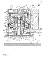
- eine Querschnittsansicht eines ersten Ausführungsbeispiels einer Handwerkzeugmaschine in Gestalt eines Exzentertellerschleifers oder einer Exzentertellerpoliermaschine,
- Figur 2
- ein zweites Ausführungsbeispiel als eine Variante der Handwerkzeugmaschine gemäß Figur 1 mit einer modifizierten Werkzeugspindel-Lagerung,
- Figur 3a
- eine Querschnittsansicht einer Blockiervorrichtung der Handwerkzeugmaschine gemäß Figur 1 in Freigabestellung,
- Figur 3b
- die Blockiervorrichtung gemäß Figur 3a in Blockierstellung,
- Figur 3c
- die Blockiervorrichtung gemäß Figuren 3a, 3b von oben,
- Figur 4a
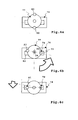
- eine schematische untere Ansicht der Blockiervorrichtung gemäß Figuren 3a, 3b, 3c, wobei ein Blockierteil und eine Feststelleinrichtung außer Eingriff sind,
- Figur 4b
- eine Drehstellung des Blockierteils gemäß Figur 4a, bei der eine erste Blockieranordnung der Feststelleinrichtung und des Blockierteils in Eingriff sind,
- Figur 4c
- eine Blockierstellung, bei der zwei Blockieranordnungen in Eingriff sind,
- Figur 5a
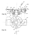
- eine Querschnittsansicht einer Blockiervorrichtung, die anstelle der Blockiervorrichtung gemäß Figuren 3a, 3b, 3c verwendbar ist, und
- Figur 5b
- die Blockiervorrichtung gemäß Figur 5a von oben.
- Soweit bei den nachfolgenden Ausführungsbeispielen gleiche oder gleichartige Bauteile vorhanden sind, sind diese mit denselben Bezugszeichen versehen und werden nicht im Einzelnen mehrfach erläutert.
- Eine Handwerkzeugmaschine 10, beispielsweise eine Exzenterschleifmaschine oder Exzenterpoliermaschine, weist einen bürstenlosen Motor 11 zum Antreiben einer Werkzeugspindel 12 auf. Am unteren Ende der Werkzeugspindel 12 ist eine Werkzeugaufnahme 13 zum Halten eines Werkzeuges 14, beispielsweise eines Schleiftellers 15, angeordnet. Der Motor 11 treibt eine Hohlwelle 16 an, in deren Hohlraum oder Innenraum 17 die Werkzeugspindel 12 zumindest abschnittsweise angeordnet ist. Der Innenraum 17 erstreckt sich über die gesamte Länge der Hohlwelle 16, die an ihren Enden offen ist. Die Werkzeugspindel 12 steht an einem oberen Endbereich 18 und einem unteren Endbereich 19 der Hohlwelle 16 vor diese vor.
- Die Hohlwelle 16 ist mit einer Hohlwellenlagerung 20 bezüglich eines Gehäuses 21 der Handwerkzeugmaschine 10 drehbar gelagert. Die Werkzeugspindel 12 wiederum ist mit einer Werkzeugspindel-Lagerung 22 an der Hohlwelle 16 drehbar gelagert. Eine Drehachse 24 der Werkzeugspindel 12 weist eine Exzentrizität e zu einer Drehachse 23 der Hohlwelle 16 auf.
- Der Motor 11 treibt die Hohlwelle 16 zu einer Drehbewegung an, die die Hohlwelle 16 über eine Kopplungsanordnung 9 zumindest teilweise auf die Werkzeugspindel 12 überträgt. Der Motor 11 bildet einen Direktantrieb zum Antreiben der Hohlwelle 16. Die Hohlwelle 16 und die Kopplungsanordnung 9 bilden einer Art Getriebe für die Werkzeugspindel 12. Die Kopplungsanordnung 9 umfasst die Werkzeugspindel-Lagerung 22. Die Hohlwelle 16 nimmt die Werkzeugspindel 12 aufgrund von Reibung bei der Werkzeugspindel-Lagerung 22 mit. Die Werkzeugspindel-Lagerung 22 ist unter anderem durch Fliehkräfte belastet. Beispielsweise ist dadurch in Werkzeugspindel-Lagern 50, 51 Reibung vorhanden.
- Die Werkzeugspindel 12 dreht sich um die Drehachse 23 und mit einer überlagerten, um die Exzentrizität e versetzten Drehbewegung um die Drehachse 24. Im vorliegenden Fall ist die Exzentrizität e durch eine außermittige Anordnung des Hohlraums oder Innenraums 17 bezüglich der Drehachse 23 der Hohlwelle 16 realisiert. Es versteht sich, dass auch bei einem zentrischen Hohlraum einer Hohlwelle durch eine geeignete Lagerung der Werkzeugspindel bezüglich der Hohlwelle eine Exzentrizität realisierbar ist.
- Die Drehzahl der Werkzeugspindel könnte aufgrund der Kopplungsanordnung 9 die Drehzahl der Hohlwelle 16 erreichen. Die Drehzahl der Werkzeugspindel 12 ist jedoch vorzugsweise geringer als die Drehzahl der Hohlwelle 16. Bei der Handwerkzeugmaschine 10 ist daher eine zwischen dem Gehäuse 21 und der Werkzeugspindel 12 wirksame Bremsanordnung 25 mit einer Wirbelstrombremse realisiert, bei der ein mit der Werkzeugspindel 12 drehfest gekoppeltes metallisches Wirbelstromelement 26 und drehfeste, am Gehäuse 21 angeordnete Magnete 27 zusammenwirken. Die Magnete 27 sind beispielsweise an einem oberen Kragenbereich einer Stützhülse 49 des Gehäuses 21 angeordnet und erzeugen Wirbelströme in dem Wirbelstromelement 26, das beim Ausführungsbeispiel durch einen Lagerhalter 29 einer Lagerhalteanordnung 30 gebildet ist. Der Lagerhalter 29 ist am oberen Endbereich 32 der Werkzeugspindel 12 beispielsweise mit einer Mutter 31 drehfest festgelegt. Ferner ist denkbar, zur Realisierung einer Bremsanordnung andere Bremskonzepte vorzusehen, z.B. Reibabschnitte an einer Werkzeugspindel in der Art der Werkzeugsspindel 12, die an gehäusefesten Reibabschnitten reiben und so die Werkzeugspindel bremsen. Z.B. könnten anstelle der Magnete 27 Reibelemente vorgesehen sein, an denen ein Abschnitt des Lagerhalters 29 reibt.
- Der Motor 11 ist ein bürstenloser, elektronisch kommutierter Antriebsmotor. Der Motor 11 ist ein Außenläufermotor. Eine Erregerspulenanordnung 33 eines Stators 34 des Motors 11 ist außen an einem Statorkörper oder einer Statorstruktur 28 angeordnet. Ein Blechpaket 35 sitzt beispielsweise am Außenumfang der Statorstruktur 28. Die Erregerspulen der Erregerspulenanordnung 33 sind am Blechpaket 35 angeordnet und erzeugen durch Bestromung mit einer Bestromungseinrichtung 36 ein Drehfeld. Dieses Drehfeld wirkt auf einen Rotor 37, der als ein Außenläufer-Rotor ausgestaltet ist.
- Magnete 38, beispielsweise Permanentmagnete, des Rotors 37 sind radial außen bezüglich des Stators an einem Rotorkörper oder einer Rotorstruktur 39 angeordnet, beispielsweise an einem becherartig hochstehenden, zylindrischen Umfangsabschnitt 40 der Rotorstruktur 39. Anstelle des wandartigen Umfangsabschnitts 40 könnten auch beispielsweise Haltestege, eine Käfigstruktur etc. zum Halten der Magnete 38 vorgesehen sein.
- Ein unterer Bereich 41 der Rotorstruktur 39 ist drehfest mit der Hohlwelle 16 verbunden. Die Hohlwelle 16 wird vom Rotor 37 unmittelbar angetrieben und bildet eine Abtriebswelle 42 des Motors 11. Die Abtriebswelle 42 ist im Innenraum des Stators 34 angeordnet. Der Rotor 37 liegt radial bezüglich der Abtriebswelle 42 weit außen, sodass ein Luftspalt 53a zwischen den Magneten 38 und der Erregerspulenanordnung 33 einen großen Durchmesser hat und der Motor 11 ein hohes Drehmoment erzeugen kann. Dennoch baut die Handwerkzeugmaschine 10 sehr kompakt. Aufgrund des hohen Drehmoments des Motors 11 ist kein Getriebe zum Antreiben der Hohlwelle 16 erforderlich.
- Ein oberes und ein unteres Lager 43, 44 der Hohlwellenlagerung 20 sind im Bereich des Motors 11 angeordnet. Die Hohlwelle 16 hat eine gestufte Struktur, sodass man auch von einer Stufenwelle sprechen kann. Die Außendurchmesser der Hohlwelle 16 nehmen von einem oberen Endabschnitt 45 zu einem oberen Abschnitt 46 über einen mittleren Abschnitt 47 bis zu einem unteren Endabschnitt 48 der Hohlwelle 16 stufenweise zu.
- Das untere Lager 44 sitzt am unteren Ende des mittleren Abschnittes 47 an der Hohlwelle 16 und stützt sich außenseitig an der Statorstruktur 28 ab. Das untere Lager 44 sitzt an der Stufe zwischen dem mittleren Abschnitt 47 und dem unteren Endabschnitt 48. Das obere Lager 43 der Hohlwellenlagerung 20 sitzt an der Stufe zwischen dem oberen Endabschnitt 45 und dem mittleren Abschnitt 46. Außenseitig stützt sich das obere Lager 43 an einer Stützstruktur oder Stützhülse 49 ab, die in die Statorstruktur 28 eingesteckt ist und sich an dieser abstützt.
- Ein oberes und ein unteres Lager 50, 51 der Werkzeugspindel-Lagerung 22 sind im Bereich der oberen und unteren Endabschnitte 45, 48 der Hohlwelle 16 angeordnet. Das obere Werkzeugspindel-Lager 50 ist bezüglich der Hohlwelle 16 ein Außenlager, das untere Werkzeugspindel-Lager 51 ein Innenlager für die Werkzeugspindel 12. Die beiden Hohlwellen-Lager 43, 44 sind vorteilhaft zwischen den Werkzeugspindel-Lagern 50, 51 angeordnet.
- Das untere Lager 51 befindet sich an einem Innenumfang der Hohlwelle 16, nämlich in einer Aufnahme 52 der Hohlwelle 16. Die Aufnahme 52 ist durch einen erweiterten Abschnitt des Innenraumes 17 der Hohlwelle 16 gebildet.
- Das obere Lager 50 hat einen größeren Durchmesser als das untere Lager 51. Das obere Lager 50 sitzt an einem Außenumfang 53 der Hohlwelle 16, nämlich am oberen Endabschnitt 45. Die Lagerhalteanordnung 30, die drehfest mit der Werkzeugspindel 12 verbunden ist, hält das obere Lager 50 an seinem Außenumfang. Die Lagerhalteanordnung 30 steht vor das obere Längsende bzw. den Endbereich 18 der Hohlwelle 16 radial vor und hält einen äußeren Lagerring 73 des oberen Werkzeugspindel-Lagers 50. An einem oberen, scheibenartigen Plattenabschnitt 55 des Lagerhalters 29 ist unten ein zylindrischer Umfangsabschnitt 54 angeordnet, der den Lagerring 73 hält.
- Die Rotorstruktur 39 umfasst ein Lüfterrad, das an der Abtriebswelle 42, die durch die Hohlwelle 16 gebildet ist, angeordnet ist. Das Lüfterrad 56 erzeugt einen Absaug-Luftstrom 57 zum Absaugen von Staub von einer durch die Handwerkzeugmaschine 10 bearbeiteten Fläche f, beispielsweise einer Holzoberfläche. Der Absaug-Luftstrom 57 tritt durch Öffnungen 58 am Werkzeug 14 in einen Absaugluftraum 59 unterhalb des Lüfterrades 56 ein und wird durch Luftführungsabschnitte oder Luftkanäle 60 am Lüfterrad 56 in einen Absaugkanal 61 des Gehäuses 21 sozusagen ausgeblasen. An den Absaugkanal 61 ist ein Auffangbehälter, beispielsweise ein Staubsack oder dergleichen, anschließbar. Zwischen dem Werkzeug 14 und dem unteren Abschnitt des Gehäuses 21 ist zweckmäßigerweise eine Dichtung 62 angeordnet, sodass der Absaug-Luftstrom 57 nicht aus dem Absaugluftraum 59 austritt. Die Luftkanäle 60 sind winkelig, wobei sich ein Abschnitt etwa parallel zu den Drehachsen 23, 24 erstreckt und ein zweiter Abschnitt nach radial außen führt, wo er in den Absaugkanal 61 mündet, wenn der jeweilige Luftkanal 60 mit dem Absaugkanal 61 bei einer geigneten Drehstellung des Lüfterrades 56 fluchtet.
- Das Lüfterrad 56 erzeugt ferner einen Motor-Kühlluftstrom 64 zur Kühlung des Motors 11. Der Kühlluftstrom 64 tritt durch Öffnungen 65 an einem Deckel 66 des Gehäuses 21 ein und strömt von dort weiter durch Kühlkanäle 67 einer Motor-Kühlluftführung 68 zum Motor 11. Die Kühlkanäle 67 sind am Gehäuse 21 ausgebildet und erstrecken sich etwa parallel zu den Drehachsen 23, 24. Die Kühlkanäle 67 führen unmittelbar zu der Erregerspulenanordnung 33, sodass im Wesentlichen die Erregerspulen gekühlt werden. Kühlkanäle 69 führen aus der Erregerspulenanordnung 33 heraus. Die Kühlkanäle 67, 69 erstrecken sich parallel zu den Drehachsen 23, 24, sodass der Kühlluftstrom 64 im Bereich der Erregerspulenanordnung 33 etwa parallel zu den Drehachsen 23, 24 verläuft. Rippen 70 an der Oberseite des Lüfterrades 56 erzeugen den Motor-Kühlluftstrom 64, der durch radial äußere Öffnungen 71 im unteren Bereich des Gehäuses 21 aus dem Gehäuse 21 austritt.
- Die Bestromungseinrichtung 36 kann die jeweilige Drehposition des Rotors 37 auf elektronischem Weg abtasten. Ferner ist es denkbar, dass beispielsweise eine Positions-Magnetanordnung 63 am Rotor 37 angeordnet ist, beispielsweise unterhalb der Luftkanäle 60, sodass ein Sensor 63' die jeweilige Drehposition des Rotors 37 mit Hilfe der Magnete 63 erfassen kann.
- Ein oberer Bereich des Gehäuses 21 dient als Handgriffbereich. Unterhalb dieses Handgriffbereiches strömt die Kühlluft 68 aus dem Gehäuse 21 aus, sodass sie einen Bediener der Handwerkzeugmaschine 10 nicht beeinträchtigt. Eine Griffmulde 72 am Außenumfang des Gehäuses 21 erleichtert das Ergreifen des Gehäuses 21. Ein Bediener kann die Handwerkzeugmaschine 10 von oben ergreifen und mit seinen Fingern in die Griffmulde 72 eingreifen. Die Handwerkzeugmaschine liegt somit gut in der Hand. Im Bereich der Griffmulde 72 kann ein Schalter zum Einschalten des Motors 11 vorgesehen sein.
- Aber auch sonst ist die Handhabung der Handwerkzeugmaschine 10 bequem. So dient beispielsweise zum Wechseln des Werkzeugs 14 an der Werkzeugaufnahme 13 eine Blockiervorrichtung 75, die die Werkzeugspindel drehfest blockiert, sodass die Werkzeugspindel 12 bewegungsfest ist, während der Bediener das Werkzeug 14 an der Werkzeugaufnahme 13 wechselt. Die Werkzeugaufnahme 13 enthält beispielsweise ein Schraubgewinde, ein Bajonett, Rastmittel oder sonstige Befestigungsmittel zum Befestigen des Werkzeugs 14.
- Eine Feststelleinrichtung 76, die zwar drehfest bezüglich der Drehachsen 23, 24 ist, aber am Gehäuse 21 beweglich gelagert ist, ist zwischen einer Freigabestellung (in Figur 1 mit durchgezogenen Linien gezeichnet) und einer in Figur 2 dargestellten Blockierstellung (in Figur 1 gestrichelt gezeichnet) beweglich. Beim Verlagern der Feststelleinrichtung 76 in Richtung der Blockierstellung greifen nacheinander ein erster Blockiervorsprung 80 einer ersten Blockieranordnung 78 in eine erste Blockieraufnahme 79 und sodann ein zweiter Blockiervorsprung 83 in eine zweite Blockieraufnahme 82 einer zweiten Blockieranordnung 81 ein. Die Blockiervorsprünge 80, 83, beispielsweise Stifte oder Dorne, sind an einem Blockierteil 77 angeordnet, das mit der Werkzeugspindel 12 bewegungsgekoppelt ist, vorliegend drehfest an der Werkzeugspindel 12 angeordnet ist. Es versteht sich, dass zwischen einem Blockierteil und der Werkzeugspindel auch beispielsweise ein Getriebe oder eine sonstige Mitnahmeeinrichtung zur Bewegungskopplung vorgesehen sein können. Das Blockierteil 77 ist vorliegend plattenartig. Das Blockierteil 77 wird durch den am oberen Ende der Werkzeugspindel 12 angeordneten Lagerhalter 29 gebildet. Vor den Lagerhalter 29 stehen die Blockiervorsprünge 80, 83 nach oben parallel zu den Drehachsen 23, 24 vor. Die Blockieraufnahmen 79, 82 sind durch Ausnehmungen 84, 85 einer Platte 86 der Feststelleinrichtung 76 gebildet.
- Die Feststelleinrichtung 76 ist entgegen der Federkraft von Federn 90 einer Rückstelleinrichtung 91 von der Freigabestellung in die Blockierstellung beweglich. Beispielsweise kann ein Bediener die Feststelleinrichtung 76 mit einer Betätigungshandhabe 88, zum Beispiel einen Betätigungsknopf, der durch eine Öffnung 87 am Gehäuse 21 beziehungsweise am Deckel 66 zugänglich ist, in Richtung des Blockierteils 77 verlagern.
- Eine Führungseinrichtung 90a mit Führungselementen 89 führt die Feststelleinrichtung 76 linear parallel zu den Drehachsen 23, 24. Die Führungselemente 89 sind beispielsweise Bolzen, die an zweckmäßigerweise vorstehende Abschnitte oder Halterungen 92 des Gehäuses 21 angeschraubt sind. Die Federn 90 stützen sich einerseits an den Halterungen 92 und andererseits an der Feststelleinrichtung 76 ab. Die Führungselemente 89 durchdringen die Feststelleinrichtung 76 an Führungsöffnungen 93. Vorsprünge 94 an den Führungselementen 89, beispielsweise Schraubenköpfe, begrenzen den Verstellweg der Feststelleinrichtung in Richtung der Freigabestellung. Ferner sind an der Betätigungshandhabe 88 Anschläge 95, beispielsweise ein Kragenabschnitt oder radial vorstehende Vorsprünge, vorgesehen, die in der Freigabestellung der Feststelleinrichtung 76 an Anschläge 96 des Gehäuses 21, beispielsweise an Anschläge im Bereich der Öffnung 87, anschlagen. Auch dadurch wird der Hub der Feststelleinrichtung 76 in Richtung der Freigabestellung begrenzt.
- Das Blockierteil 77 ist um die Drehachse 23 der durch den Motor 11 angetriebenen Hohlwelle 16 und zudem um die Drehachse 24 der Werkzeugspindel 12 drehbar, wobei die Drehachse 24 der Werkzeugspindel 12 zur Drehachse 23 der Hohlwelle 16 um die Exzentrizität e exzentrisch ist. Eine Exzentrizität erschwert an sich eine Bedienung einer Blockiervorrichtung. Insbesondere ist ein drehfestes Festlegen der Werkzeugspindel für den Werkzeugwechsel mit bekannten Blockiervorrichtungen nicht möglich. Mit der Blockiervorrichtung 75 kann die Werkzeugspindel 12 hingegen bequem drehfest blockiert werden.
- Beim Verlagern der Feststelleinrichtung 76 von der Freigabestellung in Richtung der Blockierstellung greift bei einem ersten Bewegungsabschnitt zunächst der Blockiervorsprung 80 in die Blockieraufnahme 79 ein. Der Blockiervorsprung 80 steht weiter vor den Plattenabschnitt 55 des Blockierteils 77 nach oben vor, sodass er in seine zugeordnete Blockieraufnahme 79 eingreift, bevor in einem zweiten Bewegungsabschnitt der kürzere Blockiervorsprung 83 in seine zugeordnete Blockieraufnahme 82 eingreift.
- Die erste Blockieranordnung 78 bildet eine Art Fang-Blockieranordnung, das heißt, der Pin oder Blockiervorsprung 80 greift in die Blockieraufnahme 79 ein. Diese ist beispielsweise in Figur 4b schematisch dargestellt. Sodann wird das Blockierteil 77, das oben fest an der Werkzeugspindel 12 sitzt, beispielsweise durch Drehen an der Werkzeugspindel 12 so lange weiterbewegt, bis die Blockieraufnahme 82 und der Blockiervorsprung 83 einander gegenüberstehen und einrasten können. Durch die feste Koppelung der Werkzeugspindel 12 mit dem Blockierteil 77 ist das Blockierteil 77 um beide Drehachsen 23, 24 drehbeweglich und somit exzentrisch gelagert. Durch Drehen der Werkzeugspindel 12, beispielsweise durch Ergreifen des Werkzeugs 14, ist es möglich, die beiden Blockieranordnungen 78, 81 sequenziell in ihre Eingriffsposition zu verlagern. Der Bediener drückt zum Blockieren der Werkzeugspindel 12 auf die Betätigungshandhabe 88 und dreht an der Werkzeugspindel 12 so lange, bis die Feststelleinrichtung 76 in der Blockierstellung ist und das Blockierteil 77 drehfest festlegt. Dann kann das Werkzeug 14 bequem gewechselt werden, da die Werkzeugaufnahme 13 in jeder Drehrichtung drehfest festgelegt ist.
- An der Platte 86 der Feststelleinrichtung 76 ist eine Aufnahme 97 vorgesehen, beispielsweise eine Durchtrittsöffnung, in die die Mutter 31 an der Werkzeugspindel 12 in der Blockierstellung eindringen kann. Die Aufnahme 97 ist aufgrund der Exzentrizität e zweckmäßigerweise so groß, dass ein freies Bewegungsspiel der Werkzeugspindel 12 innerhalb der Aufnahme 97 gewährleistet ist.
- Die Ausnehmungen 84, 85 für die Blockiervorsprünge 80 und 83 hingegen sind bezüglich der Drehrichtung(en) des Blockierteils 77 zweckmäßigerweise enger, sodass in der Blockierstellung die Blockiervorsprünge 80, 83 möglichst spielfrei in den Blockieraufnahmen 79, 82 aufgenommen sind.
- Nun wäre es möglich, die Blockieraufnahmen so zu gestalten, dass nur in einer einzigen Drehposition beziehungsweise Exzenterposition ein Eingreifen der Blockieranordnung 78, 81 möglich ist. Bei der Feststelleinrichtung 76 hingegen sind die Blockieraufnahmen 79, 82 gleichartig und haben die gleiche Anordnung Geometrie, sodass jeder der Blockiervorsprünge 80, 83 in jede der Blockieraufnahmen 79, 82 passt.
- Die Blockieraufnahmen 79, 82 sind beispielsweise Langlöcher oder Längsaufnahmen 98, die sich quer zur Drehachse 24 des Blockierteils 77 erstrecken. Vorliegend erstrecken sich die Längsaufnahmen 98 von der zentralen Aufnahme 97 nach radial außen weg. Die Längsaufnahmen 98 haben eine Längserstreckungslänge, die dem Durchmesser d der Blockiervorsprünge 80, 83 und zusätzlich einem doppelten Exzenterabstand e entspricht. Bei dem Blockierteil 77 sind die beiden Blockiervorsprünge 80, 83 jeweils in einem Abstand r bezogen auf die radial innere Seite der VBlockiervorsprünge 80, 83 von der Drehachse 24 des Blockierteils 77 entfernt. Dieser Abstand r definiert einen radial inneren Endbereich 99a der Längsaufnahmen 98, wo sich in Figur 3c z.B. der Blockiervorsprung 80 befindet, sowie einen erforderlichen radial äußeren Endbereich 99b, wo sich der Blockiervorsprung 83 befindet. Ein radial äußeres Ende der Längsaufnahmen 98 wird durch den Abstand r und zusätzlich den Durchmesser d der jeweiligen Blockiervorsprünge 80, 83, definiert.
- Es versteht sich, dass anstelle eines einzigen, gleichen Abstandes r der Blockieraufnahmen 79, 82 bezüglich der Drehachse 24 des Blockierteils 77 auch unterschiedliche Abstände vorgesehen sein können. Beispielsweise ist ein zu dem Blockiervorsprung 80 alternativer Blockiervorsprung 80" mit einem Radialabstand r" von der Drehachse 24 entfernt. Korrespondierend dazu ist eine als Längsaufnahme ausgestaltete Blockieraufnahme 79" ebenfalls mit dem Abstand r" zu der Drehachse 24 am Blockierteil 77 angeordnet.
- Gleiche oder gleichartige Teile der Handwerkzeugmaschinen 10 und einer in Figur 2 dargestellten Handwerkzeugmaschine 10' sind mit denselben Bezugszeichen versehen und werden nicht näher erläutert.
- Im Unterschied zur Handwerkzeugmaschine 10 ist bei der Handwerkzeugmaschine 10' eine Werkzeugspindel-Lagerung 22' vorgesehen, bei der nicht nur das obere Lager 50, sondern auch ein unteres Werkzeugspindel-Lager 51' als ein Außenlager ausgestaltet ist. Das Lager 51' sitzt am Außenumfang eines unteren Endabschnitts 48' ein Werkzeugspindel 12'. Der Endabschnitt 48' hat einen geringeren Außendurchmesser als der Endabschnitt 48. Ansonsten gleicht die Hohlwelle 16' der Hohlwelle 16. Der äußere Lagerring 73' des Werkzeugspindel-Lagers 51' wird von einem Lagerhalter 29' gehalten. Der Lagerhalter 29' ist becherartig und bildet eine Lagerhalteanordnung 30' zum Halten eines Werkzeugspindel-Lagers. Der Lagerhalter 29' ist drehfest an der Werkzeugspindel 12 angeordnet. Somit sind beide Werkzeugspindel-Lager 50, 51' Außenlager, die am Außenumfang der Hohlwelle 16' angeordnet sind und so optimal Lagerkräfte aufnehmen können. In der Praxis ist es ohne weiteres möglich, den Durchmesser des unteren Werkzeugspindel-Lagers 51' größer auszugestalten, wobei dann eine andere Ausgestaltung des Lüfterrades 56 beziehungsweise der Absaugluftführung erforderlich ist.
- Bei den Handwerkzeugmaschinen 10, 10' wäre auch eine in den Figuren 5a, 5b dargestellte Blockiervorrichtung 75' anwendbar. Eine Feststelleinrichtung 76' ist um eine Schwenkachse s schwenkbeweglich. Die Feststelleinrichtung 76' umfasst beispielsweise eine an einem Schwenklager 74' schwenkbare Platte 86'. Die Feststelleinrichtung 76' kann durch Schwenken um die Schwenkachse s von der in durchgezogenen Linien dargestellten Freigabestellung in eine in gestrichelten Linien dargestellte Blockierstellung geschwenkt werden, bei der die Feststelleinrichtung 76' mit einem Blockierteil 77 in Eingriff ist und somit die Werkzeugspindel 12 drehfest blockiert.
- Beim Verschwenken von der Freigabestellung in die Blockierstellung gelangt zunächst ein erster Blockiervorsprung 80' in Eingriff mit einer ersten Blockieraufnahme 79' an der Feststelleinrichtung 76', sodass eine erste Blockieranordnung 78' in Eingriff ist. Die Blockieranordnung 78' bildet somit eine Art Fang-Blockieranordnung. Das Blockierteil 77' ist dann sozusagen im Bereich der Blockieranordnung 78' festgelegt, kann aber beispielsweise durch Drehen an der Werkzeugspindel 12 noch weiterbewegt werden, sodass bei einem weiteren Nach-Unten-Verlagern der Feststelleinrichtung 76' in Richtung der Blockierstellung eine zweite Blockieranordnung 81' in ihre Eingriffstellung oder Blockierstellung gelangt, bei der ein zweiter Blockiervorsprung 83' in eine zweite Blockieraufnahme 82' eingreift.
- Da der erste Blockiervorsprung 80' weiter von der Schwenkachse s entfernt ist als der zweite Blockiervorsprung 83', greift der erste Blockiervorsprung 80' beim Verschwenken der Feststelleinrichtung 76' zuerst in seine zugeordnete erste Blockieraufnahme 79' ein. Die Blockiervorsprünge 80', 83' stehen nach unten vor die Platte 86' vor.
- Zumindest in der Blockierstellung kann die Werkzeugspindel 12 in eine Aufnahme 97' der Feststelleinrichtung 76 eintauchen.
- Das Blockierteil 77' ist drehfest an der Werkzeugspindel 12 angeordnet. Beispielsweise wird das Blockierteil 77' ebenfalls durch eine Lager-Halteanordnung zum Halten des oberen Werkzeugspindel-Lagers 50 gebildet. Die Blockieraufnahmen 79' sind an einem vorteilhaft ringartigen Plattenabschnitt 55' des Blockierteils 77' angeordnet.
- Die beiden Blockieraufnahmen 79', 82' sind an einander gegenüberliegenden Seiten der Drehachse 24, um 180° versetzt, angeordnet. Weitere Blockieraufnahmen 79", 82" sind in einer um 90° winkelversetzten Position zu den Blockieraufnahmen 79', 82' vorgesehen. Die Blockiervorsprünge 80', 83' können wahlweise in jede der Blockieraufnahmen 79', 79 " , 82', 82 " eingreifen, sodass das Auffinden einer geeigneten Drehposition für die Blockierstellung der Blockiervorrichtung 75' vereinfacht ist. An diesem Beispiel wird deutlich, dass die Anzahl der Blockiervorsprünge und Blockieraufnahmen an der Feststelleinrichtung und dem Blockierteil unterschiedlich sein kann.
- An ihrem freien, von der Schwenkachse s entfernten Endbereich ist die Feststelleinrichtung 76' durch eine Führungsanordnung 90a' geführt. Ein Führungselement 89' durchdringt die Feststelleinrichtung 76' an einer Führungsöffnung 93'. Das Führungselement 89' ist beispielsweise durch einen Schraubbolzen gebildet, dessen Kopf 94' einen oberen Anschlag für die Feststelleinrichtung 76' in ihrer Freigabestellung bildet. Eine Feder 90' einer Rückstelleinrichtung 91' wird beim Schwenken der Feststelleinrichtung 76' in die Blockierstellung vorgespannt. Die Feder 90' stützt sich von unten an der Feststelleinrichtung 76' ab.
- Die Blockieraufnahmen 79', 79" , 82', 82" sind als Längsaufnahmen oder Langlöcher 98' ausgestaltet, deren Längserstreckungslänge mindestens der zweifachen Exzentrizität e entspricht. Somit kann wahlweise jeder der Blockiervorsprünge 80', 83' unabhängig von der jeweiligen Exzenterlage des Blockierteils 77' in die Blockieraufnahmen 79', 79", 82', 82" eindringen.
- Die Längsaufnahmen 98' haben z.B. eine rechteckige Kontur und sind als Durchtrittsöffnungen ausgestaltet. Die auf die Drehrichtung der Werkzeugspindel 12 bezogene Breite der Langlöcher 98' entspricht etwa einer Breite der Blockiervorsprünge 80', 83', die beispielsweise durch ausgestanzte, nach unten umgebogene Abschnitte der Platte 86' gebildet sind, so dass die Werkzeugspindel 12 in der Blockierstellung kein oder kaum Drehspiel hat.
Claims (13)
- Handwerkzeugmaschine, insbesondere Exzenterschleifmaschine oder Exzenterpoliermaschine, mit einem Motor (11) zum Antreiben einer Werkzeugspindel (12) und mit einem mit der Werkzeugspindel (12) bewegungsgekoppelten, um mindestens eine Drehachse (24) drehbeweglichen Blockierteil (77; 77'), das zum Montieren oder Demontieren eines an einer Werkzeugaufnahme (13) der Werkzeugspindel (12) anordenbaren Werkzeugs (14) durch eine relativ zu dem Blockierteil (77; 77') aus einer Freigabestellung in eine Blockierstellung bewegliche Feststelleinrichtung (76; 76') blockierbar ist, wobei die Werkzeugspindel (12) in der Blockierstellung blockiert ist, dadurch gekennzeichnet, dass bei einem Bewegen der Feststelleinrichtung (76; 76') in die Blockierstellung während eines ersten Bewegungsabschnitts ein erster Blockiervorsprung (80; 80') und eine erste Blockieraufnahme (79; 79') einer ersten, an dem Blockierteil (77; 77') und der Feststelleinrichtung (76; 76') angeordneten Blockieranordnung (78; 78') in Eingriff gelangen, und dass bei einem sich an den ersten Bewegungsabschnitt anschließenden zweiten Bewegungsabschnitt ein zweiter Blockiervorsprung (83; 83') und eine zweite Blockieraufnahme (82; 82') einer zweiten, an dem Blockierteil (77; 77') und der Feststelleinrichtung (76; 76') angeordneten Blockieranordnung (81; 81') in Eingriff gelangen.
- Handwerkzeugmaschine nach Anspruch 1, dadurch gekennzeichnet, dass der erste Blockiervorsprung (80; 80') mit Bezug zu der Bewegung in die Blockierstellung vor den zweiten Blockiervorsprung (83; 83') vorsteht.
- Handwerkzeugmaschine nach Anspruch 1 oder 2, dadurch gekennzeichnet, dass die Feststelleinrichtung (76') um eine Schwenkachse (s) schwenkbeweglich gelagert ist, und die dass die erste und die zweite Blockieranordnung (78'; 81') unterschiedliche Abstände zu der Schwenkachse (s) aufweisen.
- Handwerkzeugmaschine nach einem der vorhergehenden Ansprüche, dadurch gekennzeichnet, dass die Werkzeugspindel (12) vor dem zweiten Bewegungsabschnitt beweglich, insbesondere drehbeweglich ist, wenn der erste Blockiervorsprung (80; 80') und die erste Blockieraufnahme (79; 79') in Eingriff sind, so dass das Blockierteil (77; 77'), insbesondere die Werkzeugspindel (12), in eine Position weiterbewegbar, insbesondere weiterdrehbar, ist, in der die zweite Blockieraufnahme (82; 82') und der zweite Blockiervorsprung (83; 83') einander gegenüberstehen.
- Handwerkzeugmaschine nach einem der vorhergehenden Ansprüche, dadurch gekennzeichnet, dass die dem Blockierteil (77; 77') zugeordneten Teile der ersten und der zweiten Blockieranordnung (78, 81; 78'; 81') an dem Blockierteil (77; 77') um einen Drehwinkel bezüglich der Drehachse (24) versetzt, insbesondere an einander entgegengesetzten Seiten des Blockierteils (77; 77'), angeordnet sind.
- Handwerkzeugmaschine nach einem der vorhergehenden Ansprüche, dadurch gekennzeichnet, dass das Blockierteil (77; 77') exzentrisch gelagert ist.
- Handwerkzeugmaschine nach einem der vorhergehenden Ansprüche, dadurch gekennzeichnet, dass die erste Blockieranordnung (78, 81; 78'; 81') einen ersten Abstand (r) und die zweite Blockieranordnung (78, 81; 78'; 81') einen von dem ersten Abstand (r) verschiedenen zweiten Abstand (r') zu der mindestens einen Drehachse (24) aufweisen.
- Handwerkzeugmaschine nach einem der vorhergehenden Ansprüche, dadurch gekennzeichnet, dass die erste und/oder die zweite Blockieraufnahme (79, 82; 79', 82') ein Langloch oder eine Längsaufnahme (98) aufweisen, die sich quer, insbesondere radial, zu der mindestens einen Drehachse (24) des Blockierteils (77; 77') erstrecken und ein wahlweises Eingreifen des ersten oder zweiten Blockiervorsprungs (80, 83; 80', 83') ermöglichen.
- Handwerkzeugmaschine nach Anspruch 8, dadurch gekennzeichnet, dass das Langloch oder die Längsaufnahme (98) eine Längserstreckungslänge aufweisen, die mindestens einem Durchmesser des zugeordneten Blockiervorsprungs (80, 83; 80', 83') und zudem einer zweifachen Exzentrizität (e) des Blockierteils (77; 77'), insbesondere der Werkzeugspindel (12), bezüglich der mindestens einen Drehachse (23, 24) entspricht.
- Handwerkzeugmaschine nach einem der vorhergehenden Ansprüche, dadurch gekennzeichnet, dass die Feststelleinrichtung (76; 76') zumindest während des ersten und des zweiten Bewegungsabschnitts im wesentlichen parallel zu der mindestens einen Drehachse (24) des Blockierteils (77; 77') längsverstellbar ist.
- Handwerkzeugmaschine nach einem der vorhergehenden Ansprüche, dadurch gekennzeichnet, dass das Blockierteil (77; 77') insbesondere drehfest an der Werkzeugspindel (12) angeordnet ist.
- Handwerkzeugmaschine nach einem der vorhergehenden Ansprüche, dadurch gekennzeichnet, dass die Feststelleinrichtung (76; 76') eine Aufnahme (97; 97') zum Aufnehmen der Werkzeugspindel (12) in der Blockierstellung aufweist.
- Handwerkzeugmaschine nach einem der vorhergehenden Ansprüche, dadurch gekennzeichnet, dass die Feststelleinrichtung (76; 76') und/oder das Blockierteil (77; 77') eine insbesondere armartige oder scheibenartige Platte (86) aufweist.
Applications Claiming Priority (1)
| Application Number | Priority Date | Filing Date | Title |
|---|---|---|---|
| DE200610054266 DE102006054266B3 (de) | 2006-11-17 | 2006-11-17 | Handwerkzeugmaschine mit einer Blockiervorrichtung |
Publications (2)
| Publication Number | Publication Date |
|---|---|
| EP1923172A1 true EP1923172A1 (de) | 2008-05-21 |
| EP1923172B1 EP1923172B1 (de) | 2009-07-15 |
Family
ID=38806262
Family Applications (1)
| Application Number | Title | Priority Date | Filing Date |
|---|---|---|---|
| EP20070020743 Active EP1923172B1 (de) | 2006-11-17 | 2007-10-24 | Handwerkzeugmaschine mit einer Blockiervorrichtung |
Country Status (2)
| Country | Link |
|---|---|
| EP (1) | EP1923172B1 (de) |
| DE (2) | DE102006054266B3 (de) |
Citations (2)
| Publication number | Priority date | Publication date | Assignee | Title |
|---|---|---|---|---|
| DE3234254A1 (de) * | 1981-09-23 | 1983-04-07 | Milwaukee Electric Tool Corp., 53005 Brookfield, Wis. | Motorisch betriebenes werkzeug |
| DE10330122A1 (de) * | 2003-07-04 | 2005-02-10 | Festool Gmbh | Handwerkzeugmaschine mit Blockierteil |
Family Cites Families (3)
| Publication number | Priority date | Publication date | Assignee | Title |
|---|---|---|---|---|
| US3872951A (en) * | 1973-11-06 | 1975-03-25 | Black & Decker Mfg Co | Spindle locking mechanism for rotary power device |
| DE19753304A1 (de) * | 1997-12-02 | 1999-06-10 | Scintilla Ag | Vorrichtung zur Arretierung einer Welle |
| DE19905624A1 (de) * | 1999-02-11 | 2000-08-17 | Festo Tooltechnic Gmbh & Co | Exzenterteller-Schleifmaschine |
-
2006
- 2006-11-17 DE DE200610054266 patent/DE102006054266B3/de not_active Expired - Fee Related
-
2007
- 2007-10-24 DE DE200750001065 patent/DE502007001065D1/de active Active
- 2007-10-24 EP EP20070020743 patent/EP1923172B1/de active Active
Patent Citations (2)
| Publication number | Priority date | Publication date | Assignee | Title |
|---|---|---|---|---|
| DE3234254A1 (de) * | 1981-09-23 | 1983-04-07 | Milwaukee Electric Tool Corp., 53005 Brookfield, Wis. | Motorisch betriebenes werkzeug |
| DE10330122A1 (de) * | 2003-07-04 | 2005-02-10 | Festool Gmbh | Handwerkzeugmaschine mit Blockierteil |
Also Published As
| Publication number | Publication date |
|---|---|
| EP1923172B1 (de) | 2009-07-15 |
| DE102006054266B3 (de) | 2008-01-10 |
| DE502007001065D1 (de) | 2009-08-27 |
Similar Documents
| Publication | Publication Date | Title |
|---|---|---|
| DE68918335T2 (de) | Antrieb für ein Bohr- und/oder Schlagwerkzeug. | |
| EP2086372B1 (de) | Antriebsvorrichtung für bewegliche möbelteile | |
| EP1274548B1 (de) | Maschinenwerkzeugaufnahme für ein kreissägeblatt | |
| EP1923173B1 (de) | Handwerkzeugmaschine | |
| DE10017458A1 (de) | Schleifmaschinenwerkzeugaufnahme | |
| DE10017981A1 (de) | Werkzeugaufnahme | |
| WO2020229363A1 (de) | Vorsatzgerät und hand-werkzeugmaschine mit vorsatzgerät | |
| DE102014103019A1 (de) | Werkzeugkopf für eine handgehaltene Schleifmaschine und handgehaltene Schleifmaschine | |
| CH692959A5 (de) | Vorrichtung zur Arretierung einer Welle. | |
| DE19510291A1 (de) | Handwerkzeugmaschine | |
| EP0820838B1 (de) | Schleifer mit einem mit Exzenterhub angetriebenen Werkzeug | |
| DE69102308T2 (de) | Flanschbefestigungsvorrichtung. | |
| DE102015200828A1 (de) | Werkzeugvorsatz für eine Handwerkzeugmaschine | |
| EP1923978A2 (de) | Exzenterschleifmaschine mit bürstenlosem Motor | |
| CH691893A5 (de) | Elektrohandwerkzeugmaschine. | |
| EP1902800A1 (de) | Motorspindel zum Drehantrieb von Werkzeugen an einer Werkzeugmaschine | |
| DE102008000732A1 (de) | Handwerkzeugmaschine, insbesondere handgeführte Schleifmaschine | |
| DE102015200831A1 (de) | Werkzeugvorsatz für eine Handwerkzeugmaschine | |
| EP1618990A1 (de) | Handwerkzeugmaschine, insbesondere Winkelschleifer | |
| CH693736A5 (de) | Handwerkzeugmaschine. | |
| EP1923172B1 (de) | Handwerkzeugmaschine mit einer Blockiervorrichtung | |
| DE212016000229U1 (de) | Schleifmaschine | |
| WO1999056919A1 (de) | Werkzeugmaschine mit werkzeugwechsel | |
| WO2012062521A1 (de) | Handwerkzeugmaschine mit einer spindellockvorrichtung | |
| DE3742163A1 (de) | Kupplung fuer handgefuehrte elektrowerkzeuge |
Legal Events
| Date | Code | Title | Description |
|---|---|---|---|
| PUAI | Public reference made under article 153(3) epc to a published international application that has entered the european phase |
Free format text: ORIGINAL CODE: 0009012 |
|
| AK | Designated contracting states |
Kind code of ref document: A1 Designated state(s): AT BE BG CH CY CZ DE DK EE ES FI FR GB GR HU IE IS IT LI LT LU LV MC MT NL PL PT RO SE SI SK TR |
|
| AX | Request for extension of the european patent |
Extension state: AL BA HR MK RS |
|
| 17P | Request for examination filed |
Effective date: 20080520 |
|
| AKX | Designation fees paid |
Designated state(s): DE FR GB IT |
|
| GRAP | Despatch of communication of intention to grant a patent |
Free format text: ORIGINAL CODE: EPIDOSNIGR1 |
|
| GRAS | Grant fee paid |
Free format text: ORIGINAL CODE: EPIDOSNIGR3 |
|
| GRAA | (expected) grant |
Free format text: ORIGINAL CODE: 0009210 |
|
| AK | Designated contracting states |
Kind code of ref document: B1 Designated state(s): DE FR GB IT |
|
| REG | Reference to a national code |
Ref country code: GB Ref legal event code: FG4D Free format text: NOT ENGLISH |
|
| REF | Corresponds to: |
Ref document number: 502007001065 Country of ref document: DE Date of ref document: 20090827 Kind code of ref document: P |
|
| PLBE | No opposition filed within time limit |
Free format text: ORIGINAL CODE: 0009261 |
|
| STAA | Information on the status of an ep patent application or granted ep patent |
Free format text: STATUS: NO OPPOSITION FILED WITHIN TIME LIMIT |
|
| 26N | No opposition filed |
Effective date: 20100416 |
|
| PG25 | Lapsed in a contracting state [announced via postgrant information from national office to epo] |
Ref country code: IT Free format text: LAPSE BECAUSE OF FAILURE TO SUBMIT A TRANSLATION OF THE DESCRIPTION OR TO PAY THE FEE WITHIN THE PRESCRIBED TIME-LIMIT Effective date: 20090715 |
|
| REG | Reference to a national code |
Ref country code: DE Ref legal event code: R082 Ref document number: 502007001065 Country of ref document: DE Representative=s name: PATENTANWAELTE MAGENBAUER & KOLLEGEN, DE |
|
| REG | Reference to a national code |
Ref country code: DE Ref legal event code: R081 Ref document number: 502007001065 Country of ref document: DE Owner name: FESTOOL GROUP GMBH & CO. KG, DE Free format text: FORMER OWNER: FESTOOL GMBH, 73240 WENDLINGEN, DE Effective date: 20121119 Ref country code: DE Ref legal event code: R082 Ref document number: 502007001065 Country of ref document: DE Representative=s name: PATENTANWAELTE MAGENBAUER & KOLLEGEN, DE Effective date: 20121119 Ref country code: DE Ref legal event code: R082 Ref document number: 502007001065 Country of ref document: DE Representative=s name: PATENTANWAELTE MAGENBAUER & KOLLEGEN PARTNERSC, DE Effective date: 20121119 Ref country code: DE Ref legal event code: R081 Ref document number: 502007001065 Country of ref document: DE Owner name: FESTOOL GMBH, DE Free format text: FORMER OWNER: FESTOOL GMBH, 73240 WENDLINGEN, DE Effective date: 20121119 |
|
| REG | Reference to a national code |
Ref country code: DE Ref legal event code: R082 Ref document number: 502007001065 Country of ref document: DE Representative=s name: PATENTANWAELTE MAGENBAUER & KOLLEGEN PARTNERSC, DE |
|
| REG | Reference to a national code |
Ref country code: DE Ref legal event code: R082 Ref document number: 502007001065 Country of ref document: DE Representative=s name: PATENTANWAELTE MAGENBAUER & KOLLEGEN PARTNERSC, DE Effective date: 20141104 Ref country code: DE Ref legal event code: R081 Ref document number: 502007001065 Country of ref document: DE Owner name: FESTOOL GMBH, DE Free format text: FORMER OWNER: FESTOOL GROUP GMBH & CO. KG, 73240 WENDLINGEN, DE Effective date: 20141104 |
|
| REG | Reference to a national code |
Ref country code: FR Ref legal event code: PLFP Year of fee payment: 9 |
|
| REG | Reference to a national code |
Ref country code: FR Ref legal event code: PLFP Year of fee payment: 10 |
|
| REG | Reference to a national code |
Ref country code: FR Ref legal event code: PLFP Year of fee payment: 11 |
|
| REG | Reference to a national code |
Ref country code: FR Ref legal event code: PLFP Year of fee payment: 12 |
|
| P01 | Opt-out of the competence of the unified patent court (upc) registered |
Effective date: 20230519 |
|
| PGFP | Annual fee paid to national office [announced via postgrant information from national office to epo] |
Ref country code: GB Payment date: 20231025 Year of fee payment: 17 |
|
| PGFP | Annual fee paid to national office [announced via postgrant information from national office to epo] |
Ref country code: FR Payment date: 20231023 Year of fee payment: 17 |
|
| PGFP | Annual fee paid to national office [announced via postgrant information from national office to epo] |
Ref country code: DE Payment date: 20240917 Year of fee payment: 18 |
|
| GBPC | Gb: european patent ceased through non-payment of renewal fee |
Effective date: 20241024 |
|
| PG25 | Lapsed in a contracting state [announced via postgrant information from national office to epo] |
Ref country code: GB Free format text: LAPSE BECAUSE OF NON-PAYMENT OF DUE FEES Effective date: 20241024 |
|
| PG25 | Lapsed in a contracting state [announced via postgrant information from national office to epo] |
Ref country code: FR Free format text: LAPSE BECAUSE OF NON-PAYMENT OF DUE FEES Effective date: 20241031 |