EP1922237B1 - Wagen- und deckelkombination - Google Patents
Wagen- und deckelkombination Download PDFInfo
- Publication number
- EP1922237B1 EP1922237B1 EP06779247A EP06779247A EP1922237B1 EP 1922237 B1 EP1922237 B1 EP 1922237B1 EP 06779247 A EP06779247 A EP 06779247A EP 06779247 A EP06779247 A EP 06779247A EP 1922237 B1 EP1922237 B1 EP 1922237B1
- Authority
- EP
- European Patent Office
- Prior art keywords
- dolly
- lid
- load
- combination
- reels
- Prior art date
- Legal status (The legal status is an assumption and is not a legal conclusion. Google has not performed a legal analysis and makes no representation as to the accuracy of the status listed.)
- Not-in-force
Links
- 230000015572 biosynthetic process Effects 0.000 claims abstract description 11
- 238000005755 formation reaction Methods 0.000 claims abstract description 11
- 230000004308 accommodation Effects 0.000 claims abstract description 5
- 238000010276 construction Methods 0.000 claims abstract description 5
- 235000004443 Ricinus communis Nutrition 0.000 claims description 6
- 240000000528 Ricinus communis Species 0.000 claims description 6
- 230000005540 biological transmission Effects 0.000 description 2
Images


Classifications
-
- B—PERFORMING OPERATIONS; TRANSPORTING
- B62—LAND VEHICLES FOR TRAVELLING OTHERWISE THAN ON RAILS
- B62B—HAND-PROPELLED VEHICLES, e.g. HAND CARTS OR PERAMBULATORS; SLEDGES
- B62B3/00—Hand carts having more than one axis carrying transport wheels; Steering devices therefor; Equipment therefor
- B62B3/14—Hand carts having more than one axis carrying transport wheels; Steering devices therefor; Equipment therefor characterised by provisions for nesting or stacking, e.g. shopping trolleys
- B62B3/16—Hand carts having more than one axis carrying transport wheels; Steering devices therefor; Equipment therefor characterised by provisions for nesting or stacking, e.g. shopping trolleys vertically stackable
-
- B—PERFORMING OPERATIONS; TRANSPORTING
- B62—LAND VEHICLES FOR TRAVELLING OTHERWISE THAN ON RAILS
- B62B—HAND-PROPELLED VEHICLES, e.g. HAND CARTS OR PERAMBULATORS; SLEDGES
- B62B2202/00—Indexing codes relating to type or characteristics of transported articles
- B62B2202/12—Boxes, Crates
-
- B—PERFORMING OPERATIONS; TRANSPORTING
- B62—LAND VEHICLES FOR TRAVELLING OTHERWISE THAN ON RAILS
- B62B—HAND-PROPELLED VEHICLES, e.g. HAND CARTS OR PERAMBULATORS; SLEDGES
- B62B2203/00—Grasping, holding, supporting the objects
- B62B2203/44—Clamping or supporting circumferentially
-
- B—PERFORMING OPERATIONS; TRANSPORTING
- B62—LAND VEHICLES FOR TRAVELLING OTHERWISE THAN ON RAILS
- B62B—HAND-PROPELLED VEHICLES, e.g. HAND CARTS OR PERAMBULATORS; SLEDGES
- B62B5/00—Accessories or details specially adapted for hand carts
- B62B5/04—Braking mechanisms; Locking devices against movement
- B62B5/0433—Braking mechanisms; Locking devices against movement foot operated
Definitions
- This invention relates to a dolly and lid combination for transporting loads, being of the type in which the dolly is provided with at least two strapping strands at opposite sides (or ends) of the dolly retractable on to reels and adapted to be engaged with corresponding sides (or ends) of the lid after it has been placed on top of a load (e.g. of trays or boxes), and the reels locked to secure the lid on top of the load.
- a load e.g. of trays or boxes
- Document WO 2005/028276 A discloses a dolly and lid combination for transporting loads, in which the dolly is provided with at least two strapping strands at opposite sides of the dolly suitable to be retractable on to reels and adapted to be engaged with corresponding sides of the lid after it has been placed on top of a load, wherein the dolly has upstanding formations (suitable) for location of the lid for return transportation, and the lid is of shell construction with criss-crossing stiffening webs inside, areas in the corners being sufficiently free of webs to allow for accommodation of the wheels of a like dolly when the lid has been located on the first dolly.
- the object of the invention is to provide such a dolly and lid combination that facilitates stacking of empty dollies and lids for return transportation.
- the dolly in a dolly and lid combination has upstanding formations for location of the lid for return transportation, and the lid is of shell construction with criss-crossing stiffening webs inside (e.g. extending in longitudinal and lateral directions), areas in the corners being sufficiently free of webs to allow for accommodation of the wheels of a like dolly when the lid has been located on the first dolly in an inverted disposition.
- the lid may have an overall depth of say 70mm, a thickness of shell of say 3mm results in a very compact stacking of inverted lids and dollies in alternation; however, the topmost lid should be disposed right way up to keep out rainwater; and the strapping strands can be engaged with the topmost lid, to secure the load of dollies and lids on the bottom (first) dolly.
- the upstanding formations may be formed by bent wire loops welded to the corners of the dolly frame; and the upstanding formations at one end may also include upright portions of tube forming sockets for detachably receiving the legs of an inverted generally U-shaped tubular handle.
- Two opposite sides (or usually the ends) of the dolly are preferably each provided with an inverted generally U-shaped stacking wire for location of loaded trays or boxes, which stacking wires also facilitate location of the inverted lid and the next dolly seated therein.
- the reels for the strapping strands may be accommodated in pockets below the respective sides (or ends) of the dolly, one end of each strand being secured to the respective reel on to which the strand is wound by a clock spring in the reel, while the other end is passed through a hole in the back of the respective pocket and secured by a ferrule crimped in place; and the lid is provided with recesses for engagement by the reel holders when required for securing a load.
- the base of the dolly preferably comprises wire rods or mesh in one plane, so as to provide widely distributed support for a load (e.g. of trays or boxes) or for the inverted lid, for transmission of the load of the next dolly seated therein to the bottom (first) dolly, and so on through a stack of inverted lids and dollies in alternation.
- a load e.g. of trays or boxes
- the inverted lid for transmission of the load of the next dolly seated therein to the bottom (first) dolly, and so on through a stack of inverted lids and dollies in alternation.
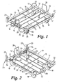
- the dolly D shown in Figures 1 and 2 has a tubular frame 10 with wire rods 11 extending longitudinally between its ends 12, 13 and welded thereto, and with a further rod 14 extending transversely below the rods 11 and welded thereto as well as to the sides 15, 16 of the frame. Also welded to the rods 11 are plates 17 carrying castors 18 at the end 12 and non-swivelling wheels 19 at the end 13, which end is also provided with 'ON' and 'OFF' pedals 20, 21 respectively for a brake mechanism for engaging the wheels 19 when necessary.
- the dolly also has upstanding formations 22 at its corners at the end 12 formed by bent loops of wire welded thereto, and upstanding formations 23 at its corners at the end 13 formed of plates 24 and upright portions of tube 25 forming sockets for detachably receiving the legs of an inverted generally U-shaped tubular handle H as shown in Figures 5 and 6 .
- the lid L shown in Figures 3 and 4 is dimensioned to locate within the corner formations 22, 23 and is of shell construction with longitudinal and lateral stiffening webs 26, 27 respectively criss-crossing inside, areas 28 in the corners being sufficiently free of webs to allow for accommodation of the wheels 18, 19 of a like dolly when the lid L has been located on the dolly D in an inverted position, as will be further described with reference to Figure 6 .
- each strand 31 is secured to the reel on to which the strand is wound by a clock spring in the reel, while the other end is passed through a hole in the back of the respective pocket 29 and secured by a ferrule (not shown) crimped in place.
- the lid L is provided with hand- holds 33 adjacent its corners for use in manoeuvring a loaded dolly in the absence of handle H, and also slots 34 for location of information cards, e.g. as to contents, customer and other data.
- Inverted generally U-shaped stacking wires 35 are also preferably provided at the ends 12, 13 of the dolly frame 10 for location of trays or boxes B, which stacking wires also facilitate location of the inverted lid L and the next dolly seated therein.
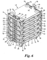
- the lid may have an overall depth of say 70mm, a thickness of shell of say 3mm enables very compact stacking of inverted lids and dollies in alternation, as shown in Figure 6 , in which the bottom dolly and lid are denoted as D1 and L1 respectively, and successive dollies and inverted lids in the stack are denoted D2, L2 to D6, L6 except that the topmost lid L6 is disposed right way up to keep out rainwater and to enable the strapping stands 31 to be engaged with the topmost lid by means of respective reel holders 30 being located in their respective recesses 32 in the lid L6, and their reels locked to secure the load of dollies and lids on the bottom dolly D1.
- the bottom dolly and lid are denoted as D1 and L1 respectively
- successive dollies and inverted lids in the stack are denoted D2, L2 to D6, L6 except that the topmost lid L6 is disposed right way up to keep out rainwater and to enable the strapping stands 31 to be engaged with the topmost lid by means of respective reel
- dollies D2 to D6 are shown orientated with their sockets 25 all at one end of the stack, the dollies and lids are not orientation sensitive as the web-free areas 28 in the corners at either end of the lids will accommodate the castors 18 at any angle.
- each dolly D1 to D6 comprises wire rods 11 in one plane, widely distributed support is provided for the inverted lids L1 to L5, for transmission of the load of successive dollies D2 to D6 seated therein to the bottom dolly D1.
Landscapes
- Engineering & Computer Science (AREA)
- Chemical & Material Sciences (AREA)
- Combustion & Propulsion (AREA)
- Transportation (AREA)
- Mechanical Engineering (AREA)
- Packages (AREA)
- Package Frames And Binding Bands (AREA)
- Handcart (AREA)
- Carriages For Children, Sleds, And Other Hand-Operated Vehicles (AREA)
- Rear-View Mirror Devices That Are Mounted On The Exterior Of The Vehicle (AREA)
- Basic Packing Technique (AREA)
- Stackable Containers (AREA)
- Vehicle Step Arrangements And Article Storage (AREA)
- Accessory Devices And Overall Control Thereof (AREA)
Claims (9)
- Kombination aus Rollwagen (D) und Deckel (L) zum Transportieren von Lasten, wobei der Rollwagen (D) an entgegengesetzten Seiten des Rollwagens (D) mit mindestens zwei Befestigungsgurten (31) versehen ist, die auf Spulen einziehbar und ausgebildet sind, um mit entsprechenden Seiten des Deckels (L) in Eingriff zu gelangen, nachdem dieser am oberen Ende einer Last angeordnet wurde, und wobei die Spulen verriegelt werden, um den Deckel (L) am oberen Ende der Last zu sichern, wobei der Rollwagen (D) aufrechte Gebilde (22, 23, 35) zum Anordnen des Deckels (L) für den Rücktransport aufweist und der Deckel (L) eine Schalenkonstruktion mit innen vorgesehenen kreuzweise verlaufenden Versteifungsrippen (26, 27) ist, wobei Bereiche in den Ecken ausreichend frei von Rippen sind, um das Unterbringen der Räder (18, 19) eines gleichen Rollwagens (D) zu ermöglichen, wenn der Deckel (L) in einer umgekehrten Anordnung auf dem ersten Rollwagen (D) angeordnet wurde.
- Kombination aus Rollwagen und Deckel nach Anspruch 1, wobei sich die Versteifungsrippen in der Längs- und der Seitenrichtung erstrecken.
- Kombination aus Rollwagen und Deckel nach Anspruch 1 oder Anspruch 2, wobei der Deckel eine Gesamttiefe von 70mm und eine Schalendicke von 3mm aufweist.
- Kombination aus Rollwagen und Deckel nach einem beliebigen der Ansprüche 1 bis 3, wobei die aufrechten Gebilde durch gebogene Drahtbügel gebildet sind, die an die Ecken des Rollwagenrahmens geschweißt sind.
- Kombination aus Rollwagen und Deckel nach einem beliebigen der Ansprüche 1 bis 4, wobei die aufrechten Gebilde an einem Ende aufrechte Rohrabschnitte umfassen, die Buchsen zum entfernbaren Aufnehmen der Beine eines umgekehrten im Allgemeinen U-förmigen rohrförmigen Griffs bilden.
- Kombination aus Rollwagen und Deckel nach einem beliebigen der Ansprüche 1 bis 5, wobei zwei entgegengesetzte Seiten des Rollwagens jeweils mit einem umgekehrten im Allgemeinen U-förmigen Stapeldraht zum Anordnen von beladenen Wannen oder Kisten versehen sind, wobei die Stapeldrähte auch das Anordnen des umgekehrten Deckels und des nächsten darin aufgenommenen Rollwagens erleichtern.
- Kombination aus Rollwagen und Deckel nach einem beliebigen der Ansprüche 1 bis 6, wobei die Spulen für die Befestigungsgurte, wenn diese nicht verwendet werden, um eine Last zu sichern, ausgebildet sind, um in Fächern unter den jeweiligen Seiten des Rollwagens aufgenommen zu werden, wobei ein Ende jedes Gurtes an der jeweiligen Spule befestigt ist, auf welche der Gurt durch eine Drehfeder in der Spule aufgewickelt wird, während das andere Ende durch ein Loch in der Rückseite des jeweiligen Faches hindurchgeführt und durch eine fest angequetschte Hülse gesichert wird; und der Deckel mit Ausnehmungen für das Eingreifen der Spulenhalterungen versehen ist, wenn dies zum Sichern einer Last erforderlich ist.
- Kombination aus Rollwagen und Deckel nach einem beliebigen der Ansprüche 1 bis 7, wobei abgesehen von dem Bereitstellen von schwenkbaren Rädern an einem Ende des Rollwagens und nichtschwenkbaren Rädern an dem anderen und von Buchsen an einem Ende für einen entfernbaren Griff Symmetrie der Enden des Deckels und der Enden des Rollwagens vorliegt, wodurch eine Mehrzahl von derartigen Rollwagen und Deckeln nicht ausrichtungsempfindlich ist und die rippenfreien Bereiche in den Ecken an beiden Enden der Deckel die schwenkbaren Räder in jedem beliebigen Winkel aufnehmen.
- Kombination aus Rollwagen und Deckel nach einem beliebigen der Ansprüche 1 bis 8, wobei die Basis des Rollwagens Drahtstäbe oder -gitter in einer Ebene umfasst.
Applications Claiming Priority (2)
| Application Number | Priority Date | Filing Date | Title |
|---|---|---|---|
| GBGB0518087.2A GB0518087D0 (en) | 2005-09-06 | 2005-09-06 | Dolly and lid combination |
| PCT/GB2006/003225 WO2007028958A1 (en) | 2005-09-06 | 2006-08-31 | Dolly and lid combination |
Publications (2)
| Publication Number | Publication Date |
|---|---|
| EP1922237A1 EP1922237A1 (de) | 2008-05-21 |
| EP1922237B1 true EP1922237B1 (de) | 2009-02-25 |
Family
ID=35220914
Family Applications (1)
| Application Number | Title | Priority Date | Filing Date |
|---|---|---|---|
| EP06779247A Not-in-force EP1922237B1 (de) | 2005-09-06 | 2006-08-31 | Wagen- und deckelkombination |
Country Status (7)
| Country | Link |
|---|---|
| EP (1) | EP1922237B1 (de) |
| AT (1) | ATE423716T1 (de) |
| DE (1) | DE602006005378D1 (de) |
| DK (1) | DK1922237T3 (de) |
| ES (1) | ES2324427T3 (de) |
| GB (1) | GB0518087D0 (de) |
| WO (1) | WO2007028958A1 (de) |
Families Citing this family (4)
| Publication number | Priority date | Publication date | Assignee | Title |
|---|---|---|---|---|
| DE102007022686B3 (de) * | 2007-05-11 | 2008-11-27 | Khs Ag | Verfahren und Vorrichtung zum Depalettieren und Fördern von Rollwagen |
| DE202009004554U1 (de) | 2009-04-02 | 2009-07-23 | Airbus Deutschland Gmbh | Platzsparend aufbewahrbarer Transportwagen zur Bestückung einer Flugzeugbordküche |
| EP2384993B1 (de) * | 2010-05-07 | 2012-11-14 | Smart Flow Europe SA | Plastikabdeckung zum Abdecken von Chargiermulden, ihre Anwendung und Kit, bestehend aus einer solchen Abdeckung und mehreren Sets dieser Mulden |
| CH703335A1 (de) * | 2010-06-23 | 2011-12-30 | Liconic Ag | Transportvorrichtung für Stapel von Käfigteilen sowie Verwendung dieser Vorrichtung. |
Family Cites Families (4)
| Publication number | Priority date | Publication date | Assignee | Title |
|---|---|---|---|---|
| US5186330A (en) * | 1991-12-27 | 1993-02-16 | Mcclure Industries, Inc. | Stackable container |
| FR2748733B1 (fr) * | 1996-05-15 | 1998-08-14 | Valeo Equip Electr Moteur | Dispositif de gerbage de chariots de manutention a roulettes |
| US6983946B2 (en) * | 2003-04-01 | 2006-01-10 | Porta Plastic Products | Transportable containers apparatus and method |
| SE526880C2 (sv) * | 2003-09-19 | 2005-11-15 | Arca Systems Internat Ab | Transportkomposition |
-
2005
- 2005-09-06 GB GBGB0518087.2A patent/GB0518087D0/en not_active Ceased
-
2006
- 2006-08-31 AT AT06779247T patent/ATE423716T1/de not_active IP Right Cessation
- 2006-08-31 WO PCT/GB2006/003225 patent/WO2007028958A1/en not_active Ceased
- 2006-08-31 EP EP06779247A patent/EP1922237B1/de not_active Not-in-force
- 2006-08-31 DK DK06779247T patent/DK1922237T3/da active
- 2006-08-31 ES ES06779247T patent/ES2324427T3/es active Active
- 2006-08-31 DE DE602006005378T patent/DE602006005378D1/de active Active
Also Published As
| Publication number | Publication date |
|---|---|
| WO2007028958A1 (en) | 2007-03-15 |
| ES2324427T3 (es) | 2009-08-06 |
| GB0518087D0 (en) | 2005-10-12 |
| EP1922237A1 (de) | 2008-05-21 |
| DE602006005378D1 (de) | 2009-04-09 |
| ATE423716T1 (de) | 2009-03-15 |
| DK1922237T3 (da) | 2009-06-15 |
Similar Documents
| Publication | Publication Date | Title |
|---|---|---|
| EP3668348B1 (de) | Stapelbare fraktionierte kunststoffpalette | |
| RU2676804C2 (ru) | Поддон для транспортировки на нем продуктов | |
| EP3060489B1 (de) | Karton mit tragegriffen | |
| EP2163486A2 (de) | Transportpalette | |
| US20110155740A1 (en) | Modular carrier apparatuses and methods thererfor | |
| EP1922237B1 (de) | Wagen- und deckelkombination | |
| WO2006065490A1 (en) | Collapsible crate | |
| KR20110130879A (ko) | 적층형 포장 상자 | |
| JP4008205B2 (ja) | 物品収納パレット | |
| JP3816495B2 (ja) | 運搬台車 | |
| EP3512784B1 (de) | Eckverbinder und behälter und transportsystem mit demselben | |
| KR20090011345U (ko) | 미닫이형 포장 상자 | |
| EP0899214A1 (de) | Verpackungsselement für einen aufgewickelten elektrischen Leiter | |
| NZ575488A (en) | Drum(s) with connection member, typically snap-fit ring, with slot(s) for securing to other drums via connectors for transport | |
| JPH11208663A (ja) | 段ボール製梱包体 | |
| JP2576758Y2 (ja) | 包装用かご | |
| JPH09301368A (ja) | パレット | |
| JP2009057058A (ja) | 運搬用梱包材 | |
| NZ514296A (en) | Packaging for broom heads and handles therefor |
Legal Events
| Date | Code | Title | Description |
|---|---|---|---|
| PUAI | Public reference made under article 153(3) epc to a published international application that has entered the european phase |
Free format text: ORIGINAL CODE: 0009012 |
|
| 17P | Request for examination filed |
Effective date: 20080221 |
|
| AK | Designated contracting states |
Kind code of ref document: A1 Designated state(s): AT BE BG CH CY CZ DE DK EE ES FI FR GB GR HU IE IS IT LI LT LU LV MC NL PL PT RO SE SI SK TR |
|
| GRAP | Despatch of communication of intention to grant a patent |
Free format text: ORIGINAL CODE: EPIDOSNIGR1 |
|
| GRAS | Grant fee paid |
Free format text: ORIGINAL CODE: EPIDOSNIGR3 |
|
| GRAA | (expected) grant |
Free format text: ORIGINAL CODE: 0009210 |
|
| AK | Designated contracting states |
Kind code of ref document: B1 Designated state(s): AT BE BG CH CY CZ DE DK EE ES FI FR GB GR HU IE IS IT LI LT LU LV MC NL PL PT RO SE SI SK TR |
|
| REG | Reference to a national code |
Ref country code: GB Ref legal event code: FG4D |
|
| REG | Reference to a national code |
Ref country code: CH Ref legal event code: EP |
|
| REG | Reference to a national code |
Ref country code: IE Ref legal event code: FG4D |
|
| REF | Corresponds to: |
Ref document number: 602006005378 Country of ref document: DE Date of ref document: 20090409 Kind code of ref document: P |
|
| REG | Reference to a national code |
Ref country code: DK Ref legal event code: T3 |
|
| REG | Reference to a national code |
Ref country code: SE Ref legal event code: TRGR |
|
| RAP2 | Party data changed (patent owner data changed or rights of a patent transferred) |
Owner name: K.HARTWALL LIMITED |
|
| PG25 | Lapsed in a contracting state [announced via postgrant information from national office to epo] |
Ref country code: LT Free format text: LAPSE BECAUSE OF FAILURE TO SUBMIT A TRANSLATION OF THE DESCRIPTION OR TO PAY THE FEE WITHIN THE PRESCRIBED TIME-LIMIT Effective date: 20090225 Ref country code: SI Free format text: LAPSE BECAUSE OF FAILURE TO SUBMIT A TRANSLATION OF THE DESCRIPTION OR TO PAY THE FEE WITHIN THE PRESCRIBED TIME-LIMIT Effective date: 20090225 Ref country code: NL Free format text: LAPSE BECAUSE OF FAILURE TO SUBMIT A TRANSLATION OF THE DESCRIPTION OR TO PAY THE FEE WITHIN THE PRESCRIBED TIME-LIMIT Effective date: 20090225 |
|
| NLV1 | Nl: lapsed or annulled due to failure to fulfill the requirements of art. 29p and 29m of the patents act | ||
| REG | Reference to a national code |
Ref country code: ES Ref legal event code: FG2A Ref document number: 2324427 Country of ref document: ES Kind code of ref document: T3 |
|
| PG25 | Lapsed in a contracting state [announced via postgrant information from national office to epo] |
Ref country code: LV Free format text: LAPSE BECAUSE OF FAILURE TO SUBMIT A TRANSLATION OF THE DESCRIPTION OR TO PAY THE FEE WITHIN THE PRESCRIBED TIME-LIMIT Effective date: 20090225 Ref country code: IS Free format text: LAPSE BECAUSE OF FAILURE TO SUBMIT A TRANSLATION OF THE DESCRIPTION OR TO PAY THE FEE WITHIN THE PRESCRIBED TIME-LIMIT Effective date: 20090625 Ref country code: AT Free format text: LAPSE BECAUSE OF FAILURE TO SUBMIT A TRANSLATION OF THE DESCRIPTION OR TO PAY THE FEE WITHIN THE PRESCRIBED TIME-LIMIT Effective date: 20090225 Ref country code: PL Free format text: LAPSE BECAUSE OF FAILURE TO SUBMIT A TRANSLATION OF THE DESCRIPTION OR TO PAY THE FEE WITHIN THE PRESCRIBED TIME-LIMIT Effective date: 20090225 |
|
| PG25 | Lapsed in a contracting state [announced via postgrant information from national office to epo] |
Ref country code: EE Free format text: LAPSE BECAUSE OF FAILURE TO SUBMIT A TRANSLATION OF THE DESCRIPTION OR TO PAY THE FEE WITHIN THE PRESCRIBED TIME-LIMIT Effective date: 20090225 Ref country code: CZ Free format text: LAPSE BECAUSE OF FAILURE TO SUBMIT A TRANSLATION OF THE DESCRIPTION OR TO PAY THE FEE WITHIN THE PRESCRIBED TIME-LIMIT Effective date: 20090225 Ref country code: PT Free format text: LAPSE BECAUSE OF FAILURE TO SUBMIT A TRANSLATION OF THE DESCRIPTION OR TO PAY THE FEE WITHIN THE PRESCRIBED TIME-LIMIT Effective date: 20090812 |
|
| PGFP | Annual fee paid to national office [announced via postgrant information from national office to epo] |
Ref country code: DK Payment date: 20090812 Year of fee payment: 4 Ref country code: ES Payment date: 20090708 Year of fee payment: 4 Ref country code: FR Payment date: 20090715 Year of fee payment: 4 |
|
| PG25 | Lapsed in a contracting state [announced via postgrant information from national office to epo] |
Ref country code: RO Free format text: LAPSE BECAUSE OF FAILURE TO SUBMIT A TRANSLATION OF THE DESCRIPTION OR TO PAY THE FEE WITHIN THE PRESCRIBED TIME-LIMIT Effective date: 20090225 Ref country code: SK Free format text: LAPSE BECAUSE OF FAILURE TO SUBMIT A TRANSLATION OF THE DESCRIPTION OR TO PAY THE FEE WITHIN THE PRESCRIBED TIME-LIMIT Effective date: 20090225 |
|
| PGFP | Annual fee paid to national office [announced via postgrant information from national office to epo] |
Ref country code: DE Payment date: 20090707 Year of fee payment: 4 Ref country code: FI Payment date: 20090714 Year of fee payment: 4 Ref country code: SE Payment date: 20090826 Year of fee payment: 4 |
|
| PLBE | No opposition filed within time limit |
Free format text: ORIGINAL CODE: 0009261 |
|
| STAA | Information on the status of an ep patent application or granted ep patent |
Free format text: STATUS: NO OPPOSITION FILED WITHIN TIME LIMIT |
|
| PG25 | Lapsed in a contracting state [announced via postgrant information from national office to epo] |
Ref country code: BG Free format text: LAPSE BECAUSE OF FAILURE TO SUBMIT A TRANSLATION OF THE DESCRIPTION OR TO PAY THE FEE WITHIN THE PRESCRIBED TIME-LIMIT Effective date: 20090525 |
|
| 26N | No opposition filed |
Effective date: 20091126 |
|
| PG25 | Lapsed in a contracting state [announced via postgrant information from national office to epo] |
Ref country code: MC Free format text: LAPSE BECAUSE OF NON-PAYMENT OF DUE FEES Effective date: 20090831 |
|
| PGFP | Annual fee paid to national office [announced via postgrant information from national office to epo] |
Ref country code: IT Payment date: 20090831 Year of fee payment: 4 |
|
| REG | Reference to a national code |
Ref country code: IE Ref legal event code: MM4A |
|
| PGFP | Annual fee paid to national office [announced via postgrant information from national office to epo] |
Ref country code: BE Payment date: 20091012 Year of fee payment: 4 |
|
| PG25 | Lapsed in a contracting state [announced via postgrant information from national office to epo] |
Ref country code: IE Free format text: LAPSE BECAUSE OF NON-PAYMENT OF DUE FEES Effective date: 20090831 |
|
| PG25 | Lapsed in a contracting state [announced via postgrant information from national office to epo] |
Ref country code: GR Free format text: LAPSE BECAUSE OF FAILURE TO SUBMIT A TRANSLATION OF THE DESCRIPTION OR TO PAY THE FEE WITHIN THE PRESCRIBED TIME-LIMIT Effective date: 20090526 |
|
| BERE | Be: lapsed |
Owner name: K.HARTWALL LTD Effective date: 20100831 |
|
| REG | Reference to a national code |
Ref country code: DK Ref legal event code: EBP |
|
| REG | Reference to a national code |
Ref country code: CH Ref legal event code: PL |
|
| PG25 | Lapsed in a contracting state [announced via postgrant information from national office to epo] |
Ref country code: LI Free format text: LAPSE BECAUSE OF NON-PAYMENT OF DUE FEES Effective date: 20100831 Ref country code: CH Free format text: LAPSE BECAUSE OF NON-PAYMENT OF DUE FEES Effective date: 20100831 Ref country code: LU Free format text: LAPSE BECAUSE OF NON-PAYMENT OF DUE FEES Effective date: 20090831 |
|
| REG | Reference to a national code |
Ref country code: SE Ref legal event code: EUG |
|
| REG | Reference to a national code |
Ref country code: FR Ref legal event code: ST Effective date: 20110502 |
|
| PG25 | Lapsed in a contracting state [announced via postgrant information from national office to epo] |
Ref country code: IT Free format text: LAPSE BECAUSE OF NON-PAYMENT OF DUE FEES Effective date: 20100831 Ref country code: FI Free format text: LAPSE BECAUSE OF NON-PAYMENT OF DUE FEES Effective date: 20100831 |
|
| REG | Reference to a national code |
Ref country code: DE Ref legal event code: R119 Ref document number: 602006005378 Country of ref document: DE Effective date: 20110301 |
|
| PG25 | Lapsed in a contracting state [announced via postgrant information from national office to epo] |
Ref country code: HU Free format text: LAPSE BECAUSE OF FAILURE TO SUBMIT A TRANSLATION OF THE DESCRIPTION OR TO PAY THE FEE WITHIN THE PRESCRIBED TIME-LIMIT Effective date: 20090826 |
|
| PG25 | Lapsed in a contracting state [announced via postgrant information from national office to epo] |
Ref country code: BE Free format text: LAPSE BECAUSE OF NON-PAYMENT OF DUE FEES Effective date: 20100831 Ref country code: FR Free format text: LAPSE BECAUSE OF NON-PAYMENT OF DUE FEES Effective date: 20100831 Ref country code: DE Free format text: LAPSE BECAUSE OF NON-PAYMENT OF DUE FEES Effective date: 20110301 |
|
| PG25 | Lapsed in a contracting state [announced via postgrant information from national office to epo] |
Ref country code: TR Free format text: LAPSE BECAUSE OF FAILURE TO SUBMIT A TRANSLATION OF THE DESCRIPTION OR TO PAY THE FEE WITHIN THE PRESCRIBED TIME-LIMIT Effective date: 20090225 Ref country code: DK Free format text: LAPSE BECAUSE OF NON-PAYMENT OF DUE FEES Effective date: 20100831 |
|
| PG25 | Lapsed in a contracting state [announced via postgrant information from national office to epo] |
Ref country code: CY Free format text: LAPSE BECAUSE OF FAILURE TO SUBMIT A TRANSLATION OF THE DESCRIPTION OR TO PAY THE FEE WITHIN THE PRESCRIBED TIME-LIMIT Effective date: 20090225 |
|
| REG | Reference to a national code |
Ref country code: ES Ref legal event code: FD2A Effective date: 20111019 |
|
| PG25 | Lapsed in a contracting state [announced via postgrant information from national office to epo] |
Ref country code: ES Free format text: LAPSE BECAUSE OF NON-PAYMENT OF DUE FEES Effective date: 20100901 |
|
| PG25 | Lapsed in a contracting state [announced via postgrant information from national office to epo] |
Ref country code: SE Free format text: LAPSE BECAUSE OF NON-PAYMENT OF DUE FEES Effective date: 20100901 |
|
| PGFP | Annual fee paid to national office [announced via postgrant information from national office to epo] |
Ref country code: GB Payment date: 20140821 Year of fee payment: 9 |
|
| GBPC | Gb: european patent ceased through non-payment of renewal fee |
Effective date: 20150831 |
|
| PG25 | Lapsed in a contracting state [announced via postgrant information from national office to epo] |
Ref country code: GB Free format text: LAPSE BECAUSE OF NON-PAYMENT OF DUE FEES Effective date: 20150831 |