EP1922219B1 - Fahrzeugdach - Google Patents
Fahrzeugdach Download PDFInfo
- Publication number
- EP1922219B1 EP1922219B1 EP06791359A EP06791359A EP1922219B1 EP 1922219 B1 EP1922219 B1 EP 1922219B1 EP 06791359 A EP06791359 A EP 06791359A EP 06791359 A EP06791359 A EP 06791359A EP 1922219 B1 EP1922219 B1 EP 1922219B1
- Authority
- EP
- European Patent Office
- Prior art keywords
- roof
- vehicle
- segment
- drainage channel
- sealing
- Prior art date
- Legal status (The legal status is an assumption and is not a legal conclusion. Google has not performed a legal analysis and makes no representation as to the accuracy of the status listed.)
- Not-in-force
Links
- XLYOFNOQVPJJNP-UHFFFAOYSA-N water Substances O XLYOFNOQVPJJNP-UHFFFAOYSA-N 0.000 claims abstract description 42
- 238000007789 sealing Methods 0.000 claims description 45
- 230000007704 transition Effects 0.000 claims description 6
- 238000005192 partition Methods 0.000 description 2
- 238000009825 accumulation Methods 0.000 description 1
- 230000000712 assembly Effects 0.000 description 1
- 238000000429 assembly Methods 0.000 description 1
- 238000007599 discharging Methods 0.000 description 1
- 238000011144 upstream manufacturing Methods 0.000 description 1
Images




Classifications
-
- B—PERFORMING OPERATIONS; TRANSPORTING
- B60—VEHICLES IN GENERAL
- B60J—WINDOWS, WINDSCREENS, NON-FIXED ROOFS, DOORS, OR SIMILAR DEVICES FOR VEHICLES; REMOVABLE EXTERNAL PROTECTIVE COVERINGS SPECIALLY ADAPTED FOR VEHICLES
- B60J7/00—Non-fixed roofs; Roofs with movable panels, e.g. rotary sunroofs
- B60J7/08—Non-fixed roofs; Roofs with movable panels, e.g. rotary sunroofs of non-sliding type, i.e. movable or removable roofs or panels, e.g. let-down tops or roofs capable of being easily detached or of assuming a collapsed or inoperative position
- B60J7/12—Non-fixed roofs; Roofs with movable panels, e.g. rotary sunroofs of non-sliding type, i.e. movable or removable roofs or panels, e.g. let-down tops or roofs capable of being easily detached or of assuming a collapsed or inoperative position foldable; Tensioning mechanisms therefor, e.g. struts
- B60J7/14—Non-fixed roofs; Roofs with movable panels, e.g. rotary sunroofs of non-sliding type, i.e. movable or removable roofs or panels, e.g. let-down tops or roofs capable of being easily detached or of assuming a collapsed or inoperative position foldable; Tensioning mechanisms therefor, e.g. struts with a plurality of rigid plate-like elements or rigid non plate-like elements, e.g. with non-slidable, but pivotable or foldable movement
- B60J7/143—Non-fixed roofs; Roofs with movable panels, e.g. rotary sunroofs of non-sliding type, i.e. movable or removable roofs or panels, e.g. let-down tops or roofs capable of being easily detached or of assuming a collapsed or inoperative position foldable; Tensioning mechanisms therefor, e.g. struts with a plurality of rigid plate-like elements or rigid non plate-like elements, e.g. with non-slidable, but pivotable or foldable movement for covering the passenger compartment
-
- B—PERFORMING OPERATIONS; TRANSPORTING
- B60—VEHICLES IN GENERAL
- B60J—WINDOWS, WINDSCREENS, NON-FIXED ROOFS, DOORS, OR SIMILAR DEVICES FOR VEHICLES; REMOVABLE EXTERNAL PROTECTIVE COVERINGS SPECIALLY ADAPTED FOR VEHICLES
- B60J7/00—Non-fixed roofs; Roofs with movable panels, e.g. rotary sunroofs
- B60J7/0053—Collapsible lateral roof side beams
- B60J7/0061—Collapsible lateral roof side beams where the beam moves inwardly during folding of roof, e.g. by swiveling, sliding or translation, to disconnect the beam from windshield header
-
- B—PERFORMING OPERATIONS; TRANSPORTING
- B60—VEHICLES IN GENERAL
- B60J—WINDOWS, WINDSCREENS, NON-FIXED ROOFS, DOORS, OR SIMILAR DEVICES FOR VEHICLES; REMOVABLE EXTERNAL PROTECTIVE COVERINGS SPECIALLY ADAPTED FOR VEHICLES
- B60J7/00—Non-fixed roofs; Roofs with movable panels, e.g. rotary sunroofs
- B60J7/0084—Water draining for non-fixed roofs or roof panels
-
- B—PERFORMING OPERATIONS; TRANSPORTING
- B60—VEHICLES IN GENERAL
- B60J—WINDOWS, WINDSCREENS, NON-FIXED ROOFS, DOORS, OR SIMILAR DEVICES FOR VEHICLES; REMOVABLE EXTERNAL PROTECTIVE COVERINGS SPECIALLY ADAPTED FOR VEHICLES
- B60J7/00—Non-fixed roofs; Roofs with movable panels, e.g. rotary sunroofs
- B60J7/02—Non-fixed roofs; Roofs with movable panels, e.g. rotary sunroofs of sliding type, e.g. comprising guide shoes
- B60J7/04—Non-fixed roofs; Roofs with movable panels, e.g. rotary sunroofs of sliding type, e.g. comprising guide shoes with rigid plate-like element or elements, e.g. open roofs with harmonica-type folding rigid panels
- B60J7/043—Sunroofs e.g. sliding above the roof
Definitions
- the invention relates to a vehicle roof having at least two rigid roof segments, which are adjustable between a closed position covering a vehicle interior and a storage position releasing the vehicle interior.
- Such a vehicle roof is for example from the DE 3808224 A1 or the DE 195 39 086 C1 known and designed as a so-called RHT (Retractable Hard Top) roof of a motor vehicle designed as a convertible.
- That from the DE 195 39 086 C1 known vehicle roof is formed in five parts and includes a front, adjacent to a front cowl roof segment, which is bounded on both sides in each case by a Dacheuerholmsegment in the closed position of the roof. Adjacent to the front roof segment is a central roof segment, to which in turn borders a rear roof segment. Starting from the closed position, the individual roof segments can be pivoted one above the other so that they can be stored in a top storage box.
- the front roof segment is to be designed as a cover element of an outside sliding roof, it is necessary that guides for the cover element are formed both in the area of the two roof side rails and in the area of the middle roof segment.
- carrier elements In particular in the area of the middle roof segment, carrier elements must be able to engage in the guides by slots extending in the vehicle longitudinal direction.
- sealing devices can be provided in the region of the slots, which are penetrated by carrier elements of the lid element. In the field of guides can However, despite the sealing devices leakages lead to an undesirable accumulation of leakage water.
- the invention has for its object to provide a vehicle roof of the type mentioned in the introduction, which is provided with an outboard sunroof and can be removed in the leak water from the region of the guides of the sunroof in a simple manner.
- the essence of the invention is therefore to provide a designed as a so-called RHT vehicle roof of a convertible in the area of the guide assemblies of an outboard sunroof with a water collection device that collects leakage water and can carry away in the vehicle longitudinal direction, water leakage from above in the roof Slots penetrates into the guide arrangement of the tiltable sunroof, so that the function of the sliding roof and an opening and closing mechanism of the vehicle roof does not affect and not drain uncontrollably from the roof segments when placing the vehicle roof in the top storage box, but rather be dissipated harmless.
- the drainage channel drainage deeper areas of the guide arrangements is possible.
- the drain hose which in particular branches off at the rear end side, is guided, for example, along a handlebar system for opening and closing the vehicle roof to a wheel housing on the respective guide arrangement side or a side window shaft.
- the drain hose has a bellows-like insert, which increases the flexibility of the drain hose in critical areas.
- the water drainage channel is provided on its front end side with a connecting piece which engages in the closed position of the vehicle roof in an opening of a front cowl.
- This opening is then suitably connected to a drainage channel, which leads for example via an A-pillar of the relevant vehicle side to a front wheel well and discharges the leak water on this.
- the leak water can then be discharged independently of the inclination direction of the vehicle or the water drainage channel.
- the rear water drain hose is provided with a tee in which a channel arranged between the roof systems Sealing and drainage system opens.
- the sealing and drainage system must then not be provided with possibly disturbing openings to the vehicle outside.
- the design of a vehicle roof according to the invention is particularly advantageous if the vehicle roof has two Dachinterholmsegmente, between which a front, serving as Ausstellschiebedeckel roof segment and a central roof segment are arranged, followed by a rear roof segment in the closed position, wherein between the Dachinterholmsegmenten one hand and the front roof segment and the middle roof segment, on the other hand, each have a guide arrangement for the extension sliding cover is arranged and the sealing and drainage system is arranged in the closed position in the transition areas between the individual segments.
- the guide arrangement for the outside sunroof cover element is then fixed to the roof side spar segments and the middle roof segment.
- the Dach facedholmsegmente can be pivoted in a particular embodiment of the vehicle roof according to the invention with respect to the vehicle longitudinal center plane to the outside and then stored in a top storage box, the front ends of Dachinholmsegmente are then stored laterally next to a back seat.
- Such pivoting of the roof side rail segments increases the lateral space in the rear of the vehicle.
- the water drainage channel assigned to the respective guide arrangement is preferably provided with an elastically elongated section in the region of the transition between the sections. This can be formed in particular Wellbalgartig.
- the sealing and dewatering system is preferably designed to have at least one trough-like section on which the channel leading to the T-piece of the rear drain hose exits. This counteracts overflow of the sealing and drainage system even with large amounts of water leakage.
- the fixation of the water gutter can be done in many ways, but is executed in a preferred embodiment of the vehicle roof according to the invention such that the water gutter is latched to the guide assembly. This can be done by means of the drainage channel on both sides formed locking rails, which engage in each case in a corresponding undercut of the relevant guide arrangement.
- a vehicle roof 10 is shown, which is a so-called RHT (Retractable Hard Top) as a convertible executed motor vehicle and is selectively adjustable between a vehicle interior overlapping a closed position and the vehicle interior releasing storage position.
- RHT Retractable Hard Top
- Fig. 1 the closed position is shown, in which the vehicle roof 10 forms a rigid roof skin of the vehicle in question.
- the vehicle roof 10 can be stored to release the vehicle interior in a rear-side, also not shown here, executed in the usual way folding top box.
- the vehicle roof 10 comprises a front roof segment 12, a middle roof segment 14 and a rear roof segment 16 which receives a rear window 18 of the motor vehicle and comprises so-called C pillars 20 of the main vehicle body. Furthermore, the vehicle roof 10 comprises a left roof side rail segment 22A and a right roof side rail segment 22B, which extend in the vehicle longitudinal direction and laterally limit the front roof segment 12 and the central roof segment 14 in the closed position of the vehicle roof 10. As Fig. 5 it can be seen in the Fig. 1 illustrated closed position, the front free end faces of the Dachactedholmsegmente 22A and 22B to an A-pillars of the vehicle body connecting front cowl 84th
- the opening of the vehicle roof 10 takes place such that initially the front roof segment 12, which is designed as an externally running sliding roof cover element is moved over the middle roof segment 14, the Dachinflammatoryholmsegmente 22A, 22B relative to the vehicle longitudinal center plane pivoted outwards, the rear roof segment 16 via the unit formed by the front roof segment 12 and the central roof segment 14 is pivoted and then the package of middle roof segment 14, front roof segment 12, rear roof segment 16 and Dachifholmsegmenten 22A, 22B is stored by means of a handlebar system, not shown here in the top storage box.
- the front roof segment 12 which is designed as an externally running sunroof cover element, is movable in an otherwise closed vehicle roof 10 for opening a roof opening bounded by the Dachrichholmsegmenten 22A, 22B, the front cowl and the central roof segment 14 separately rearward on the central roof segment 14.
- guide arrangements 24A, 24B are provided which extend in the closed position of the vehicle roof 10 along the respective associated roof side rail segment 22A or 22B and, in particular Fig. 7 can be seen with respect to the left roof area, each comprising a guide rail 26, in which a sliding element 28 is guided displaceably in the vehicle longitudinal direction, which is connected via a carrier 30 with the front roof segment 12.
- the sword-like support 30 When retracting the front roof segment 12 via the central roof segment 14, the sword-like support 30 passes through a slot between the central roof segment 14 and the associated roof side rail segment 22A or 22B, which by means of a particular in Fig. 2 illustrated sealing and drainage system 32 is sealed.
- the sealing and drainage system 32 extends along the boundaries of the vehicle roof 10 as well as along the transitions between the individual roof segments 12, 14, 16, 22A and 22B.
- the sealing and drainage system 32 is in Fig. 2 shown for the left in the direction of travel of the vehicle roof 10. In the right area of the vehicle roof 10, the sealing and drainage system 32 is mirror-symmetrical thereto.
- the sealing and drainage system 32 includes in the right area of the vehicle roof 10, an outer sealing profile 34 which is disposed between the Dachforceholmsegment 22A and side windows of the vehicle not shown here, a subsequent to the sealing profile 34 sealing profile 35, the rear roof segment 16 laterally limited and connects to a rear side window of the vehicle body. Furthermore, a rear sealing profile 40 is formed at a lower edge of the rear roof segment 16, which seals a gap between the rear roof segment 16 and a convertible top compartment lid in the closed state of the vehicle roof 10. For sealing a gap between the rear roof segment 16 and the middle roof segment 14, a sealing profile 42 extending in the vehicle transverse direction is provided.
- a sealing profile 44 extending in the vehicle transverse direction is likewise formed.
- sealing profile 46 is provided, which is fixed to the Dachinholmsegment 22A.
- a further sealing profile 48 is formed in the area between the roof side rail segment 22A and the middle roof segment 14.
- Fig. 7 can be seen on the basis of the sealing profiles 34 and 46, the sealing profiles each have a primary tube 50 and a secondary lip 52. Between the primary tube 50 and the secondary lip 52 is in each case a leak water channel 54th
- a flexible water-conducting film 55 is stretched, which thus sealingly connects the roof side rail segment 22A to the guide rail 26 and, if necessary, directs any resulting leakage water into the region of the guide rail 26. This is particularly advantageous if the roof joint course does not run parallel to the guide rail.
- a water drainage channel 56 made of plastic is furthermore arranged, which is fixed by means of latching rails 58A and 58B to corresponding latching rails 60A and 60B of the guide rail 26.
- the water drainage channel 56 has an end wall 62 on the rear side with an opening, to which a water drain hose 64 adjoins.
- the water drain hose 64 which is provided for receiving movements of the handlebar system for opening and closing the vehicle roof with a bellows-like portion 66, is guided along the handlebar system for opening and closing the vehicle roof and connected in the region of the rear left wheel house with the vehicle exterior. In the water drainage channel 56 collected water can thus be controlled discharged via the drain hose 64 and the wheel arch to the environment.
- the drain hose 64 Upstream of the bellows-like portion 66, the drain hose 64 is provided with a T-piece 68, on which a channel 70 opens, which is connected to a trough-like portion 72 in the region of a leakage gutter of arranged between the rear roof segment 16 and the central roof segment 14 sealing profile 42 , which is also provided with a primary tube and a secondary lip, between which lies the leak water channel.
- This leak water channel is further provided with a partition 74 interrupted, which is located on the vehicle longitudinal center plane farther outside than the trough-like portion 72 and which ensures that substantially no leakage water, which accumulates in the sealing profile 42, flows to the outside, but rather on the trough-like portion 72 and the branching channel of this 70 is led to the drain hose 64 and from there to the relevant wheel arch.
- the water drainage channel 56 further has a front end wall 76, which is provided with a trunk-like .Wässausstutzen 78 which cooperates in the closed position of the vehicle roof 10 with a corresponding opening 80 of a fitting 82 of the front cowl 84 and for this purpose has a sealing lip 86.
- a centering of the water outlet connection piece 78 with respect to the opening 80 takes place by means of a closure pin 88 formed on the respective roof side rail segment 22A or 22B, which engages in a corresponding opening 90 of the fitting 82.
- Leaking water draining to the front flows out of the water drainage channel 56 via the water drainage pipe into a hose 81 adjoining the opening 80 and plugged onto the fitting 82, which is led through an A-pillar of the vehicle body to a front wheelhouse.
- the water drainage channel 56 has in a central region a flexible, elastically elongated bellows-like portion 92 which lies in the transition region between a front and a rear portion of the guide rail 26 and allows relative movements between the two guide rail sections to be accommodated.
- the front guide rail section can be pivoted outward with respect to the vehicle longitudinal median plane together with the roof side rail segment 22A, 22B, respectively the rear guide rail section is fixed to the central roof segment 14.
- a corresponding water drainage channel is arranged in the area of the right-hand guide arrangement 24B.
Landscapes
- Engineering & Computer Science (AREA)
- Mechanical Engineering (AREA)
- Seal Device For Vehicle (AREA)
- Body Structure For Vehicles (AREA)
- Vehicle Waterproofing, Decoration, And Sanitation Devices (AREA)
- Vehicle Interior And Exterior Ornaments, Soundproofing, And Insulation (AREA)
- Fittings On The Vehicle Exterior For Carrying Loads, And Devices For Holding Or Mounting Articles (AREA)
Description
- Die Erfindung betrifft ein Fahrzeugdach mit mindestens zwei starren Dachsegmenten, die zwischen einer einen Fahrzeuginnenraum überdeckenden Schließstellung und einer den Fahrzeuginnenraum freigebenden Ablagestellung verstellbar sind.
- Ein derartiges Fahrzeugdach ist beispielsweise aus der
DE 3808224 A1 oder derDE 195 39 086 C1 bekannt und als so genanntes RHT(Retractable Hard Top)-Dach eines als Cabriolet ausgeführten Kraftfahrzeugs ausgebildet. Das aus derDE 195 39 086 C1 bekannte Fahrzeugdach ist fünfteilig ausgebildet und umfasst ein vorderes, an einen vorderen Windlauf grenzendes Dachsegment, das in Schließstellung des Daches beidseits jeweils von einem Dachseitenholmsegment begrenzt ist. An das vordere Dachsegment grenzt ein mittleres Dachsegment, an welches wiederum ein hinteres Dachsegment grenzt. Ausgehend von der Schließstellung können die einzelnen Dachsegmente so übereinander verschwenkt werden, dass sie in einem Verdeckablagekasten ablegbar sind. - Wenn nun das vordere Dachsegment als Deckelelement eines außen laufenden Schiebedachs ausgebildet sein soll, ist es erforderlich, dass sowohl im Bereich der beiden Dachseitenholme als auch im Bereich des mittleren Dachsegments Führungen für das Deckelelement ausgebildet sind. Insbesondere im Bereich des mittleren Dachsegments müssen Trägerelemente durch sich in Fahrzeuglängsrichtung erstreckende Schlitze in die Führungen eingreifen können. Zur Dichtung können im Bereich der Schlitze Dichteinrichtungen vorgesehen sein, welche von Trägerelementen des Deckelelements durchgriffen werden. Im Bereich der Führungen kann es aber trotz der Dichteinrichtungen zu Undichtigkeiten zu einer unerwünschten Ansammlung von Leckwasser kommen.
- Der Erfindung liegt die Aufgabe zugrunde, ein Fahrzeugdach der einleitend genannten Gattung bereitzustellen, das mit einem außen laufenden Schiebedach versehen ist und bei dem Leckwasser aus dem Bereich der Führungen des Schiebedachs in einfacher Weise abgeführt werden kann.
- Diese Aufgabe ist erfindungsgemäß durch das Fahrzeugdach mit den Merkmalen des Patentanspruchs 1 gelöst.
- Der Kern der Erfindung liegt mithin darin, ein als so genanntes RHT ausgeführtes Fahrzeugdach eines Cabriolets im Bereich der Führungsanordnungen eines außen laufenden Schiebedachs mit einer Wasserauffangvorrichtung zu versehen, die Leckwasser sammelt und in Fahrzeuglängsrichtung abtransportieren kann, Leckwasser, das von oben über im dem Dach vorhandene Schlitze in die Führungsanordnung des ausstellbaren Schiebedachs eindringt, kann damit die Funktion des Schiebedachs und einer Öffnungs- und Schließmechanik des Fahrzeugdachs nicht beeinträchtigen und beim Ablegen des Fahrzeugdaches in dem Verdeckablagekasten auch nicht unkontrolliert von den Dachsegmenten abtropfen, sondern vielmehr unschädlich abgeführt werden. Mit der Wasserablaufrinne ist auch eine Entwässerung tiefer liegender Bereiche der Führungsanordnungen möglich.
- Zum Abführen des Leckwassers aus der insbesondere aus Kunststoff gefertigten Wasserablaufrinne kann diese in ihrem hinteren Bereich über einen Ablaufschlauch entleerbar sein. Der Ablaufschlauch, der insbesondere an der hinteren Stirnseite abzweigt, ist beispielsweise entlang eines Lenkersystems zum Öffnen und Schließen des Fahrzeugsdachs zu einem Radkasten auf der betreffenden Führungsanordnungsseite oder einem Seitenscheibenschacht geführt.
- Um Bewegungen des Lenkersystems aufnehmen zu können, ist es vorteilhaft, wenn der Ablaufschlauch einen faltenbalgartigen Einsatz hat, der die Flexibilität des Ablaufschlauchs in kritischen Bereichen erhöht.
- Des Weiteren ist es vorteilhaft, wenn die Wasserablaufrinne an ihrer vorderen Stirnseite mit einem Stutzen versehen ist, der in Schließstellung des Fahrzeugdachs in eine Öffnung eines vorderen Windlaufs eingreift. Diese Öffnung ist dann zweckmäßigerweise mit einem Ablaufkanal verbunden, der beispielsweise über eine A-Säule der betreffenden Fahrzeugseite zu einem vorderen Radkasten führt und das Leckwasser über diesen abführt. Das Leckwasser kann dann unabhängig von der Neigungsrichtung des Fahrzeugs bzw. der Wasserablaufrinne abgeführt werden.
- Um auch Leckwasser, das sich in einem zwischen den Dachsegmenten angeordneten Dicht- und Entwässerungssystem ansammelt, in kontrollierter Weise abführen zu können, ist es vorteilhaft, wenn der hintere Wasserablaufschlauch mit einem T-Stück versehen ist, in das ein Kanal eines zwischen den Dachsystemen angeordneten Dicht- und Entwässerungssystems mündet. Das Dicht- und Entwässerungssystem muss dann nicht mit gegebenenfalls störenden Öffnungen zur Fahrzeugaußenseite versehen sein.
- Die Auslegung eines Fahrzeugdachs im Sinne der Erfindung ist insbesondere vorteilhaft, wenn das Fahrzeugdach zwei Dachseitenholmsegmente aufweist, zwischen denen ein vorderes, als Ausstellschiebedeckel dienendes Dachsegment und ein mittleres Dachsegment angeordnet sind, an das sich in Schließstellung ein hinteres Dachsegment anschließt, wobei zwischen den Dachseitenholmsegmenten einerseits und dem vorderen Dachsegment und dem mittleren Dachsegment andererseits jeweils eine Führungsanordnung für den Ausstellschiebedeckel angeordnet ist und das Dicht- und Entwässerungssystem in Schließstellung in den Übergangsbereichen zwischen den einzelnen Segmenten angeordnet ist. Die Führungsanordnung für das außen laufende Schiebedachdeckelement ist dann an den Dachseitenholmsegmenten und dem mittleren Dachsegment fixiert.
- Die Dachseitenholmsegmente können bei einer speziellen Ausführungsform des Fahrzeugsdachs nach der Erfindung bezogen auf die Fahrzeuglängsmittelebene nach außen verschwenkt werden und dann in einem Verdeckablagekasten abgelegt werden, wobei die vorderen Enden der Dachseitenholmsegmente dann seitlich neben einer Rückbank abgelegt sind. Ein derartiges Verschwenken der Dachseitenholmsegmente erhöht das seitliche Platzangebot im Fondbereich des Fahrzeugs. Bei dieser Ausführungsform ist es zweckmäßig, wenn die Führungsanordnungen beidseits des außen laufenden Schiebedachdeckelelements jeweils aus zwei Teilstücken gebildet sind. Das vordere Teilstück wird dann mit dem jeweiligen Dachseitenholmsegment nach außen geschwenkt, wohingegen das hintere Teilstück mit dem mittleren Dachsegment verbunden bleibt. Um die Relativbewegung zwischen den beiden Teilstücken der jeweiligen Führungsanordnung aufnehmen zu können, ist die der jeweiligen Führungsanordnung zugeordnete Wasserablaufrinne vorzugsweise im Bereich des Übergangs zwischen den Teilstücken mit einem elastisch längbaren Abschnitt versehen. Dieser kann insbesondere wellbalgartig ausgebildet sein.
- Das Dicht- und Entwässerungssystem ist vorzugsweise so ausgebildet, dass es mindestens einen wannenartigen Abschnitt aufweist, an dem der zu dem T-Stück des hinteren Ablaufschlauchs führende Kanal austritt. Dies wirkt einem Überlaufen des Dicht- und Entwässerungssystems auch bei großen Leckwassermengen entgegen.
- Die Fixierung der Wasserablaufrinne kann in vielfältiger Weise erfolgen, ist aber bei einer bevorzugten Ausführungsform des Fahrzeugdachs nach der Erfindung derart ausgeführt, dass die Wasserablaufrinne an der Führungsanordnung verrastet ist. Dies kann mittels an der Wasserablaufrinne beidseits ausgebildeten Rastschienen erfolgen, die jeweils in einen korrespondierenden Hinterschnitt der betreffenden Führungsanordnung eingreifen.
- Weitere Vorteile und vorteilhafte Ausgestaltungen des Gegenstands nach der Erfindung sind der Beschreibung, der Zeichnung und den Patentansprüchen entnehmbar.
- Ein Ausführungsbeispiel des Fahrzeugdachs nach der Erfindung ist in der Zeichnung schematisch vereinfacht dargestellt und wird in der nachfolgenden Beschreibung näher erläutert. Es zeigt
- Fig. 1
- eine perspektivische Draufsicht auf ein Fahrzeugdach nach der Erfindung;
- Fig. 2
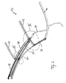
- ein Dicht- und Entwässerungssystem des Fahrzeugsdachs nach
Fig. 1 ; - Fig. 3
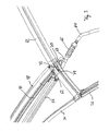
- eine vergrößerte Ansicht des Bereichs III in
Fig. 2 ; - Fig. 4
- eine vergrößerte Ansicht eines vorderen Stirnbereichs einer Entwässerungsrinne;
- Fig. 5
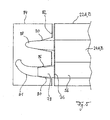
- einen stark schematisierten Schnitt durch einen Windlauf mit damit verbundenem Dachseitenholsegment;
- Fig. 6
- eine vergrößerte Ansicht des Bereichs VI in
Fig. 2 ; und - Fig. 7
- einen schematischen Schnitt entlang der Linie VII-VII in
Fig. 1 . - In
Fig. 1 ist ein Fahrzeugdach 10 dargestellt, das ein sogenanntes RHT (Retractable Hard Top) eines als Cabriolet ausgeführten Kraftfahrzeugs ist und wahlweise zwischen einer einen Fahrzeuginnenraum überdeckenden Schließstellung und einer den Fahrzeuginnenraum freigebenden Ablagestellung verstellbar ist. InFig. 1 ist die Schließstellung dargestellt, in der das Fahrzeugdach 10 eine starre Dachhaut des betreffenden Fahrzeugs bildet. Das Fahrzeugdach 10 kann zur Freigabe des Fahrzeuginnenraums in einem heckseitigen, hier ebenfalls nicht näher dargestellten, in üblicher Weise ausgeführten verdeckablagekasten abgelegt werden. - Das Fahrzeugdach 10 umfasst ein vorderes Dachsegment 12, ein mittleres Dachsegment 14 und ein hinteres Dachsegment 16, das eine Heckscheibe 18 des Kraftfahrzeugs aufnimmt und sogenannte C-Säulen 20 des Fahrzeughauptbaus umfasst. Des Weiteren umfasst das Fahrzeugdach 10 ein linkes Dachseitenholmsegment 22A und ein rechtes Dachseitenholmsegment 22B, welche sich in Fahrzeuglängsrichtung erstrecken und in Schließstellung des Fahrzeugdachs 10 das vordere Dachsegment 12 und das mittlere Dachsegment 14 seitlich begrenzen. Wie
Fig. 5 zu entnehmen ist, grenzen in der inFig. 1 dargestellten Schließstellung die vorderen freien Stirnseiten der Dachseitenholmsegmente 22A und 22B an einen A-Säulen des Fahrzeugaufbaus verbindenden vorderen Windlauf 84. - Das Öffnen des Fahrzeugdachs 10 erfolgt derart, dass zunächst das vordere Dachsegment 12, das als außen laufendes Schiebedachdeckelelement ausgeführt ist, über das mittlere Dachsegment 14 verfahren wird, die Dachseitenholmsegmente 22A, 22B bezogen auf die Fahrzeuglängsmittelebene nach außen verschwenkt werden, das hintere Dachsegment 16 über die aus dem vorderen Dachsegment 12 und dem mittleren Dachsegment 14 gebildete Einheit verschwenkt wird und dann das Paket aus mittlerem Dachsegment 14, vorderem Dachsegment 12, hinterem Dachsegment 16 und Dachseitenholmsegmenten 22A, 22B mittels eines hier nicht näher dargestellten Lenkersystems in dem Verdeckablagekasten abgelegt wird.
- Das vordere Dachsegment 12, das als außen laufendes Schiebedachdeckelelement ausgebildet ist, ist bei ansonsten geschlossenen Fahrzeugdach 10 zur Öffnung einer von den Dachseitenholmsegmenten 22A, 22B, dem vorderen Windlauf und dem mittleren Dachsegment 14 begrenzten Dachöffnung separat nach hinten über das mittlere Dachsegment 14 verfahrbar. Zur Führung des vorderen Dachsegmentes 12 sind Führungsanordnungen 24A, 24B vorgesehen, die sich in Schließstellung des Fahrzeugdachs 10 entlang des jeweils zugeordneten Dachseitenholmsegmentes 22A bzw. 22B erstrecken und, wie insbesondere
Fig. 7 bezüglich des linken Dachbereichs zu entnehmen ist, jeweils eine Führungsschiene 26 umfassen, in der ein Gleitelement 28 in Fahrzeuglängsrichtung verschiebbar geführt ist, das über einen Träger 30 mit dem vorderen Dachsegment 12 verbunden ist. Beim Zurückfahren des vorderen Dachsegmentes 12 über das mittlere Dachsegment 14 durchgreift der schwertartige Träger 30 einen Schlitz zwischen dem mittleren Dachsegment 14 und dem zugeordneten Dachseitenholmsegment 22A bzw. 22B, welcher mittels eines insbesondere inFig. 2 dargestellten Dicht- und Entwässerungssystems 32 abgedichtet ist. - Das Dicht- und Entwässerungssystem 32 erstreckt sich entlang der Begrenzungen des Fahrzeugdachs 10 sowie entlang der Übergänge zwischen den einzelnen Dachsegmenten 12, 14, 16, 22A und 22B. Das Dicht- und Entwässerungssystem 32 ist in
Fig. 2 für den in Fahrtrichtung linken Bereich des Fahrzeugdachs 10 dargestellt. Im rechten Bereich des Fahrzeugdachs 10 ist das Dicht- und Entwässerungssystem 32 spiegelsymmetrisch hierzu ausgebildet. - Das Dicht- und Entwässerungssystem 32 umfasst im rechten Bereich des Fahrzeugdachs 10 ein äußeres Dichtprofil 34, das zwischen dem Dachseitenholmsegment 22A und hier nicht näher dargestellten Seitenfenstern des Fahrzeugs angeordnet ist, ein sich an das Dichtprofil 34 anschließendes Dichtprofil 35, das das hintere Dachsegment 16 seitlich begrenzt und sich an ein hinteres Seitenfenster des Fahrzeugaufbaus anschließt. Des Weiteren ist an einem unteren Rand des hinteren Dachsegments 16 ein hinteres Dichtprofil 40 ausgebildet, das im geschlossenen Zustand des Fahrzeugdachs 10 einen Spalt zwischen dem hinteren Dachsegment 16 und einem Verdeckablagekastendeckel dichtet. Zur Dichtung eines Spalts zwischen dem hinteren Dachsegment 16 und dem mittleren Dachsegment 14 ist ein sich in Fahrzeugquerrichtung erstreckendes Dichtprofil 42 vorgesehen. Zur Dichtung eines Spalts zwischen dem mittleren Dachsegment 14 und dem vorderen Dachsegment 12 ist ebenfalls ein sich in Fahrzeugquerrichtung erstreckendes Dichtprofil 44 ausgebildet. Entlang der Innenseite des Dachseitenholmsegmentes 22A ist ein sich in Fahrzeuglängsrichtung erstreckendes Dichtprofil 46 vorgesehen, das an dem Dachseitenholmsegment 22A fixiert ist. Im Bereich zwischen dem Dachseitenholmsegment 22A und dem mittleren Dachsegment 14 ist ein weiteres Dichtprofil 48 ausgebildet. Beim Zurückfahren des vorderen, als außen laufendes Schiebedach ausgebildeten Dachsegmentes 14 verfährt der Träger 30 zwischen dem Dichtprofil 48 und dem Dichtprofil 46 nach hinten bzw. beim Schließen des vorderen Dachsegmentes 12 nach vorne.
- Wie insbesondere
Fig. 7 an Hand der Dichtprofile 34 und 46 zu entnehmen ist, weisen die Dichtprofile jeweils einen Primärschlauch 50 und eine Sekundärlippe 52 auf. Zwischen dem Primärschlauch 50 und der Sekundärlippe 52 liegt jeweils eine Leckwasserrinne 54. - Des Weiteren ist zwischen dem Dichtprofil 46 und der Führungsschiene 26 eine flexible Wasserleitfolie 55 gespannt, die damit das Dachseitenholmsegment 22A mit der Führungsschiene 26 dichtend verbindet und gegebenenfalls anfallendes Leckwasser in den Bereich der Führungsschiene 26 leitet. Dies ist insbesondere vorteilhaft, wenn der Dachfugenverlauf nicht parallel zur Führungsschiene verläuft.
- Unter der Führungsschiene 26 ist des Weiteren eine aus Kunststoff gefertigte Wasserablaufrinne 56 angeordnet, die mittels Rastschienen 58A und 58B an korrespondierenden Rastschienen 60A und 60B der Führungsschiene 26 fixiert ist.
- Die Wasserablaufrinne 56 hat heckseitig eine Stirnwand 62 mit einer Öffnung, an die sich ein Wasserablaufschlauch 64 anschließt. Der Wasserablaufschlauch 64, der zur Aufnahme von Bewegungen des Lenkersystems zum Öffnen und Schließen des Fahrzeugdachs mit einem wellbalgartigen Abschnitt 66 versehen ist, ist entlang des Lenkersystems zum Öffnen und Schließen des Fahrzeugdachs geführt und im Bereich des hinteren linken Radkastens mit der Fahrzeugaußenseite verbunden. In der Wasserablaufrinne 56 gesammeltes Wasser kann damit kontrolliert über den Ablaufschlauch 64 und den Radkasten an die Umgebung abgeführt werden.
- Stromauf des wellbalgartigen Abschnitts 66 ist der Ablaufschlauch 64 mit einem T-Stück 68 versehen, an dem ein Kanal 70 mündet, der mit einem wannenartigen Abschnitt 72 im Bereich einer Leckwasserrinne des zwischen dem hinteren Dachsegment 16 und dem mittleren Dachsegment 14 angeordneten Dichtprofils 42 verbunden ist, das ebenfalls mit einem Primärschlauch und einer Sekundärlippe versehen ist, zwischen welchen die Leckwasserrinne liegt. Diese Leckwasserrinne ist des Weiteren mit einer Trennwand 74 unterbrochen, die bezogen auf die Fahrzeuglängsmittelebene weiter außen als der wannenartige Abschnitt 72 liegt und die gewährleistet, dass im Wesentlichen kein Leckwasser, das sich in dem Dichtprofil 42 ansammelt, nach außen fließt, sondern vielmehr über den wannenartigen Abschnitt 72 und den von diesem abzweigenden Kanal 70 zu dem Ablaufschlauch 64 und von dort zu dem betreffenden Radkasten geführt wird.
- Die Wasserablaufrinne 56 hat des Weiteren eine vordere Stirnwand 76, die mit einem rüsselartigen.Wasserablaufstutzen 78 versehen ist, der in Schließstellung des Fahrzeugdachs 10 mit einer korrespondierenden Öffnung 80 eines Beschlags 82 des vorderen Windlaufs 84 zusammenwirkt und hierzu eine Dichtlippe 86 aufweist. Eine Zentrierung des Wasserablaufstutzens 78 bezüglich der Öffnung 80 erfolgt mittels eines an dem betreffenden Dachseitenholmsegment 22A bzw. 22B ausgebildeten Verschlusszapfens 88, der in eine korrespondierende Öffnung 90 des Beschlags 82 eingreift. Nach vorne ablaufendes Leckwasser strömt aus der Wasserablaufrinne 56 über den Wasserablaufstutzen in einen sich an die Öffnung 80 anschließenden und an dem Beschlag 82 aufgesteckten Schlauch 81, der durch eine A-Säule des Fahrzeugaufbaus zu einem vorderen Radkasten geführt ist.
- Des Weiteren weist die Wasserablaufrinne 56 in einem mittleren Bereich einen flexiblen, elastisch längbaren wellbalgartigen Abschnitt 92 auf, der im Übergangsbereich zwischen einem vorderen und einem hinteren Teilstück der Führungsschiene 26 liegt und ermöglicht, dass Relativbewegungen zwischen den beiden Führungsschienenteilstücken aufgenommen werden. Damit kann das vordere Führungsschienenteilstück beim Öffnen des Fahrzeugdachs 10 zusammen mit dem Dachseitenholmsegment 22A bzw. 22B bezüglich der Fahrzeuglängsmittelebene nach außen geschwenkt werden, wohingegen das hintere Führungsschienenteilstück an dem mittleren Dachsegment 14 fixiert ist.
- Im Bereich der rechten Führungsanordnung 24B ist eine entsprechende, hier nicht näher dargestellte Wasserablaufrinne angeordnet.
-
- 10
- Fahrzeugdach
- 12
- vorderes Dachsegment
- 14
- mittleres Dachsegment
- 16
- hinteres Dachsegment
- 18
- Heckscheibe
- 20
- C-Säule
- 22A, 22B
- Dachseitenholmsegment
- 24A, 24B
- Führungsanordnungen
- 26
- Führungsschiene
- 28
- Gleitelement
- 30
- Träger
- 32
- Dicht- und Entwässerungssystem
- 34
- Dichtprofil
- 36
- Dichtprofil
- 38
- Dichtprofil
- 40
- Dichtprofil
- 42
- Dichtprofil
- 44
- Dichtprofil
- 46
- Dichtprofil
- 48
- Dichtprofil
- 50
- Primärschlauch
- 52
- Sekundärlippe
- 54
- Leckwasserrinne
- 55
- Wasserleitfolie
- 56
- Wasserablaufrinne
- 58A, 58B
- Rastschiene
- 60A, 60B
- Rastschiene
- 62
- Stirnseite
- 64
- Wasserablaufschlauch
- 66
- Abschnitt
- 68
- T-Stück
- 70
- Kanal
- 72
- Abschnitt
- 74
- Trennwand
- 76
- Stirnwand
- 78
- Wasserablaufstutzen
- 80
- Öffnung
- 81
- Schlauch
- 82
- Beschlag
- 84
- Windlauf
- 86
- Dichtlippe
- 88
- Verschlusszapfen
- 90
- Öffnung
- 92
- Abschnitt
Claims (9)
- Fahrzeugdach, mit mindestens zwei starren Dachsegmenten (12, 14, 16), die zwischen einer einen Fahrzeuginnenraum überdeckenden Schließstellung und einer den Fahrzeuginnenraum freigebenden Ablagestellung verstellbar sind und die in Schließstellung in Fahrzeuglängsrichtung hintereinanderliegend angeordnet und in Ablagestellung in einem Verdeckablagekasten verstaut sind, dadurch gekennzeichnet, dass ein Dachsegment (12) als außen laufendes Schiebedachdeckelelement ausgebildet ist, das beidseits jeweils in einer sich in Fahrzeuglängsrichtung erstreckenden Führungsanordnung (24A, 24B) geführt ist, unter der eine sich in Fahrzeuglängsrichtung erstreckende Wasserablaufrinne (56) angeordnet ist.
- Fahrzeugdach nach Anspruch 1, dadurch gekennzeichnet, dass die Wasserablaufrinne (56) in ihrem heckseitigen Bereich über einen an die Fahrzeugaußenseite führenden Ablaufschlauch (64) entleerbar ist.
- Fahrzeugdach nach Anspruch 2, dadurch gekennzeichnet, dass der Ablaufschlauch (64) entlang eines Lenkersystems zu einem Radkasten des Fahrzeugs führt.
- Fahrzeugdach nach Anspruch 2 oder 3, dadurch gekennzeichnet, dass der Ablaufschlauch (64) einen faltenbalgartigen Einsatz (66) hat.
- Fahrzeugdach nach einem der Ansprüche 1 bis 4, dadurch gekennzeichnet, dass die Wasserablaufrinne (56) an ihrer vorderen Stirnseite mit einem Stutzen (78) versehen ist, der in Schließstellung in eine korrespondierende Öffnung (80) eines Ablaufkanals () im Bereich eines vorderen Windlaufs (84) des Fahrzeugs eingreift.
- Fahrzeugdach nach einem der Ansprüche 2 bis 4, dadurch gekennzeichnet, dass der hintere Wasserablaufschlauch (64) mit einem T-Stück (68) versehen ist, in das ein Kanal (70) eines zwischen den Dachsegmenten (12, 14,16) angeordneten Dicht- und Entwässerungssystems (32) mündet.
- Fahrzeugdach nach Anspruch 6, dadurch gekennzeichnet, dass zwei Dachseitenholmsegmente (22A, 22B) vorgesehen sind, zwischen denen ein vorderes, als außen laufender Schiebedeckel dienendes Dachsegment (12) und ein mittleres Dachsegment (14) angeordnet sind, an das sich in Schließstellung ein hinteres Dachsegment (16) anschließt, wobei zwischen den Dachseitenholmsegmenten (22A, 22B) einerseits und dem vorderen Dachsegment (12) und dem mittleren Dachsegment (14) andererseits jeweils die Führungsanordnung (24A, 24B) angeordnet ist und das Dicht- und Entwässerungssystem (32) in Schließstellung zwischen den einzelnen Segmenten in den Übergangsbereichen zwischen den einzelnen Segmenten (12, 14, 16, 22A, 22B) angeordnet ist.
- Fahrzeugdach nach einem der Ansprüche 1 bis 7, dadurch gekennzeichnet, dass die Wasserablaufrinne (56) an der Führungsanordnung (24A, 24B) verrastet ist.
- Fahrzeugdach nach einem der Ansprüche 1 bis 8, dadurch gekennzeichnet, dass die Führungsanordnung (24A, 24B) aus mindestens zwei Teilstücken gebildet ist und die Wasserablaufrinne (56) im Bereich des Übergangs zwischen den Teilstücken mit einem elastisch längbaren Abschnitt (92) versehen ist.
Applications Claiming Priority (2)
| Application Number | Priority Date | Filing Date | Title |
|---|---|---|---|
| DE102005043020A DE102005043020B3 (de) | 2005-09-09 | 2005-09-09 | Fahrzeugdach |
| PCT/DE2006/001566 WO2007028371A1 (de) | 2005-09-09 | 2006-09-06 | Fahrzeugdach |
Publications (2)
| Publication Number | Publication Date |
|---|---|
| EP1922219A1 EP1922219A1 (de) | 2008-05-21 |
| EP1922219B1 true EP1922219B1 (de) | 2010-02-24 |
Family
ID=37503001
Family Applications (1)
| Application Number | Title | Priority Date | Filing Date |
|---|---|---|---|
| EP06791359A Not-in-force EP1922219B1 (de) | 2005-09-09 | 2006-09-06 | Fahrzeugdach |
Country Status (6)
| Country | Link |
|---|---|
| US (1) | US7578549B2 (de) |
| EP (1) | EP1922219B1 (de) |
| JP (1) | JP4656345B2 (de) |
| AT (1) | ATE458640T1 (de) |
| DE (2) | DE102005043020B3 (de) |
| WO (1) | WO2007028371A1 (de) |
Families Citing this family (9)
| Publication number | Priority date | Publication date | Assignee | Title |
|---|---|---|---|---|
| FR2912089B1 (fr) * | 2007-02-05 | 2009-04-17 | Heuliez Sa | Toit escamotable equipe d'un dispositif d'etancheite et vehicule automobile comprenant un tel toit escamotable |
| US7866739B2 (en) * | 2008-07-24 | 2011-01-11 | Honda Motor Co., Ltd. | Motor vehicle having a sunroof system with a contoured draintube |
| DE102008063142A1 (de) | 2008-12-24 | 2009-08-27 | Daimler Ag | SHD-Ablaufschlauch |
| EP2353906B1 (de) * | 2010-01-26 | 2013-03-20 | Inalfa Roof Systems Group B.V. | Dachanordnung und Verfahren zur Montage eines Siebelements |
| MX354834B (es) | 2013-06-18 | 2017-10-18 | Continental Structural Plastics Inc | Sello con intervalos constantes para paneles removibles de vehículos. |
| DE102016103809A1 (de) * | 2016-03-03 | 2017-09-07 | Dr. Ing. H.C. F. Porsche Aktiengesellschaft | Einrichtung zum Entwässern eines innenliegenden Schiebedachs eines Kraftfahrzeugs |
| KR102472090B1 (ko) * | 2017-01-20 | 2022-12-01 | 가부시끼 가이샤 구보다 | 작업차 |
| JP2019051780A (ja) * | 2017-09-14 | 2019-04-04 | アイシン精機株式会社 | 車両用ルーフの排水装置 |
| DE102021115015A1 (de) * | 2021-06-10 | 2022-12-15 | Bayerische Motoren Werke Aktiengesellschaft | Dach für einen Kraftwagen, insbesondere für einen Personenkraftwagen, sowie Kraftwagen |
Family Cites Families (10)
| Publication number | Priority date | Publication date | Assignee | Title |
|---|---|---|---|---|
| US4892351A (en) * | 1987-03-13 | 1990-01-09 | Honda Giken Kogyo K.K. | Water drain trough for automotive sunroof |
| DE19540413C1 (de) * | 1995-03-31 | 1996-10-31 | Webasto Karosseriesysteme | Rahmen eines öffnungsfähigen Fahrzeugdaches |
| DE19539086C1 (de) * | 1995-10-20 | 1996-10-31 | Webasto Karosseriesysteme | Betätigungsmechanik für ein schwenkbares Dachteil eines Fahrzeuges |
| DE19807327C1 (de) * | 1998-02-20 | 1999-09-09 | Webasto Karosseriesysteme | Umwandelbares Fahrzeugdach |
| DE19837506B4 (de) * | 1998-08-19 | 2007-12-06 | Bayerische Motoren Werke Ag | Stoff-Faltverdeck für ein Cabriolet-Fahrzeug |
| DE19957049A1 (de) * | 1999-11-26 | 2001-06-07 | Parat Automotive Schoenenbach | Cabriolet-Verdeck |
| DE10137031C1 (de) * | 2001-07-30 | 2002-12-05 | Daimler Chrysler Ag | Entwässerungsanordnung für ein Klappdach eines Hardtop-Fahrzeuges |
| JP2004098805A (ja) * | 2002-09-06 | 2004-04-02 | Oi Seisakusho Co Ltd | サンルーフのドレンキャップ取付構造 |
| DE10248349A1 (de) * | 2002-10-17 | 2004-05-06 | Wilhelm Karmann Gmbh | Cabriolet-Fahrzeug |
| FR2892978B1 (fr) * | 2005-11-04 | 2007-12-14 | Heuliez Sa | Dispositif d'evacuation |
-
2005
- 2005-09-09 DE DE102005043020A patent/DE102005043020B3/de not_active Expired - Fee Related
-
2006
- 2006-09-06 EP EP06791359A patent/EP1922219B1/de not_active Not-in-force
- 2006-09-06 WO PCT/DE2006/001566 patent/WO2007028371A1/de not_active Ceased
- 2006-09-06 US US12/066,291 patent/US7578549B2/en not_active Expired - Fee Related
- 2006-09-06 AT AT06791359T patent/ATE458640T1/de active
- 2006-09-06 JP JP2008529463A patent/JP4656345B2/ja not_active Expired - Fee Related
- 2006-09-06 DE DE502006006267T patent/DE502006006267D1/de active Active
Also Published As
| Publication number | Publication date |
|---|---|
| WO2007028371A1 (de) | 2007-03-15 |
| ATE458640T1 (de) | 2010-03-15 |
| US20080224503A1 (en) | 2008-09-18 |
| DE102005043020B3 (de) | 2007-02-01 |
| JP4656345B2 (ja) | 2011-03-23 |
| DE502006006267D1 (de) | 2010-04-08 |
| EP1922219A1 (de) | 2008-05-21 |
| US7578549B2 (en) | 2009-08-25 |
| JP2009506937A (ja) | 2009-02-19 |
Similar Documents
| Publication | Publication Date | Title |
|---|---|---|
| DE19943765C5 (de) | Dichtungssystem an einem Kraftfahrzeug | |
| DE102005030055B4 (de) | Fahrzeugdach mit einem oberhalb des Daches verschiebbaren Dachteil | |
| DE102014013772B4 (de) | Fahrzeug mit einer Fahrzeugtür | |
| DE102005043020B3 (de) | Fahrzeugdach | |
| DE10139977C2 (de) | Fahrzeug mit einer verschließbaren Dachöffnung | |
| EP1826048A1 (de) | Cabriolet-Fahrzeug mit einer Hauptsäule | |
| DE102010021400B4 (de) | Gestängeklappenanordnung und Fahrzeug mit einer solchen Gestängeklappenanordnung | |
| DE10341526B4 (de) | Fahrzeugdach mit abzudichtenden Bauteilübergängen | |
| DE102005051768B3 (de) | Fahrzeug mit einem öffnungsfähigen Fahrzeugdach | |
| EP1744920B1 (de) | Dachstruktur für ein zu öffnendes starres kraftfahrzeugdach | |
| DE10159301B4 (de) | Fahrzeugdach mit einem Wasserablauf für eine Dachöffnung | |
| EP1690720B1 (de) | Wasserabflusseinrichtung, insbesondere für von dem Dachbereich eines Fahrzeuges zugeordneten Abdeckteilen | |
| DE19807327C1 (de) | Umwandelbares Fahrzeugdach | |
| DE102007017136A1 (de) | Faltdach für Kraftfahrzeuge | |
| DE10135406A1 (de) | Fahrzeugdach mit einer Dachöffnung | |
| DE102005030056B3 (de) | Fahrzeugdach mit einem oberhalb des Daches verschiebbaren Dachteil | |
| WO2013164058A1 (de) | Rahmenanordnung eines öffnungsfähigen fahrzeugdaches | |
| DE4444539C2 (de) | Fahrzeugdach mit wenigstens einem öffnungsfähigen Dachteil | |
| DE102004017328B4 (de) | Dichtungsanordnung für ein verstellbares Fahrzeugdach | |
| DE10216766B4 (de) | Fahrzeugdach und Verfahren zur Bildung eines Fahrzeugdaches | |
| DE102006054395B4 (de) | Cabriolet-Fahrzeug mit einem aufragenden Säulenteil des Daches | |
| WO2007118468A1 (de) | Fahrzeugdach mit einem bewegbaren deckel und einer unter dessen hinterkante angeordneten wasserrinne | |
| EP1984197B1 (de) | Fahrzeugdach | |
| DE202006002765U1 (de) | Entwässerungsanordnung | |
| DE102007042344B4 (de) | Fahrzeug mit einem Fahrzeugdach mit wenigstens zwei relativ zueinander bewegbaren Dachteilen |
Legal Events
| Date | Code | Title | Description |
|---|---|---|---|
| PUAI | Public reference made under article 153(3) epc to a published international application that has entered the european phase |
Free format text: ORIGINAL CODE: 0009012 |
|
| 17P | Request for examination filed |
Effective date: 20080318 |
|
| AK | Designated contracting states |
Kind code of ref document: A1 Designated state(s): AT BE BG CH CY CZ DE DK EE ES FI FR GB GR HU IE IS IT LI LT LU LV MC NL PL PT RO SE SI SK TR |
|
| RIN1 | Information on inventor provided before grant (corrected) |
Inventor name: BETZL, THOMAS Inventor name: BROSS, ALEXANDER |
|
| GRAP | Despatch of communication of intention to grant a patent |
Free format text: ORIGINAL CODE: EPIDOSNIGR1 |
|
| DAX | Request for extension of the european patent (deleted) | ||
| GRAS | Grant fee paid |
Free format text: ORIGINAL CODE: EPIDOSNIGR3 |
|
| GRAA | (expected) grant |
Free format text: ORIGINAL CODE: 0009210 |
|
| AK | Designated contracting states |
Kind code of ref document: B1 Designated state(s): AT BE BG CH CY CZ DE DK EE ES FI FR GB GR HU IE IS IT LI LT LU LV MC NL PL PT RO SE SI SK TR |
|
| REG | Reference to a national code |
Ref country code: GB Ref legal event code: FG4D Free format text: NOT ENGLISH |
|
| REG | Reference to a national code |
Ref country code: CH Ref legal event code: EP |
|
| REG | Reference to a national code |
Ref country code: IE Ref legal event code: FG4D Free format text: LANGUAGE OF EP DOCUMENT: GERMAN |
|
| REF | Corresponds to: |
Ref document number: 502006006267 Country of ref document: DE Date of ref document: 20100408 Kind code of ref document: P |
|
| REG | Reference to a national code |
Ref country code: NL Ref legal event code: VDEP Effective date: 20100224 |
|
| LTIE | Lt: invalidation of european patent or patent extension |
Effective date: 20100224 |
|
| PG25 | Lapsed in a contracting state [announced via postgrant information from national office to epo] |
Ref country code: IS Free format text: LAPSE BECAUSE OF FAILURE TO SUBMIT A TRANSLATION OF THE DESCRIPTION OR TO PAY THE FEE WITHIN THE PRESCRIBED TIME-LIMIT Effective date: 20100624 Ref country code: LT Free format text: LAPSE BECAUSE OF FAILURE TO SUBMIT A TRANSLATION OF THE DESCRIPTION OR TO PAY THE FEE WITHIN THE PRESCRIBED TIME-LIMIT Effective date: 20100224 Ref country code: PT Free format text: LAPSE BECAUSE OF FAILURE TO SUBMIT A TRANSLATION OF THE DESCRIPTION OR TO PAY THE FEE WITHIN THE PRESCRIBED TIME-LIMIT Effective date: 20100625 |
|
| PG25 | Lapsed in a contracting state [announced via postgrant information from national office to epo] |
Ref country code: LV Free format text: LAPSE BECAUSE OF FAILURE TO SUBMIT A TRANSLATION OF THE DESCRIPTION OR TO PAY THE FEE WITHIN THE PRESCRIBED TIME-LIMIT Effective date: 20100224 Ref country code: SI Free format text: LAPSE BECAUSE OF FAILURE TO SUBMIT A TRANSLATION OF THE DESCRIPTION OR TO PAY THE FEE WITHIN THE PRESCRIBED TIME-LIMIT Effective date: 20100224 Ref country code: FI Free format text: LAPSE BECAUSE OF FAILURE TO SUBMIT A TRANSLATION OF THE DESCRIPTION OR TO PAY THE FEE WITHIN THE PRESCRIBED TIME-LIMIT Effective date: 20100224 Ref country code: PL Free format text: LAPSE BECAUSE OF FAILURE TO SUBMIT A TRANSLATION OF THE DESCRIPTION OR TO PAY THE FEE WITHIN THE PRESCRIBED TIME-LIMIT Effective date: 20100224 |
|
| REG | Reference to a national code |
Ref country code: IE Ref legal event code: FD4D |
|
| PG25 | Lapsed in a contracting state [announced via postgrant information from national office to epo] |
Ref country code: IE Free format text: LAPSE BECAUSE OF FAILURE TO SUBMIT A TRANSLATION OF THE DESCRIPTION OR TO PAY THE FEE WITHIN THE PRESCRIBED TIME-LIMIT Effective date: 20100224 Ref country code: GR Free format text: LAPSE BECAUSE OF FAILURE TO SUBMIT A TRANSLATION OF THE DESCRIPTION OR TO PAY THE FEE WITHIN THE PRESCRIBED TIME-LIMIT Effective date: 20100525 Ref country code: ES Free format text: LAPSE BECAUSE OF FAILURE TO SUBMIT A TRANSLATION OF THE DESCRIPTION OR TO PAY THE FEE WITHIN THE PRESCRIBED TIME-LIMIT Effective date: 20100604 Ref country code: EE Free format text: LAPSE BECAUSE OF FAILURE TO SUBMIT A TRANSLATION OF THE DESCRIPTION OR TO PAY THE FEE WITHIN THE PRESCRIBED TIME-LIMIT Effective date: 20100224 Ref country code: CY Free format text: LAPSE BECAUSE OF FAILURE TO SUBMIT A TRANSLATION OF THE DESCRIPTION OR TO PAY THE FEE WITHIN THE PRESCRIBED TIME-LIMIT Effective date: 20100224 Ref country code: NL Free format text: LAPSE BECAUSE OF FAILURE TO SUBMIT A TRANSLATION OF THE DESCRIPTION OR TO PAY THE FEE WITHIN THE PRESCRIBED TIME-LIMIT Effective date: 20100224 Ref country code: RO Free format text: LAPSE BECAUSE OF FAILURE TO SUBMIT A TRANSLATION OF THE DESCRIPTION OR TO PAY THE FEE WITHIN THE PRESCRIBED TIME-LIMIT Effective date: 20100224 Ref country code: SE Free format text: LAPSE BECAUSE OF FAILURE TO SUBMIT A TRANSLATION OF THE DESCRIPTION OR TO PAY THE FEE WITHIN THE PRESCRIBED TIME-LIMIT Effective date: 20100224 |
|
| PG25 | Lapsed in a contracting state [announced via postgrant information from national office to epo] |
Ref country code: BG Free format text: LAPSE BECAUSE OF FAILURE TO SUBMIT A TRANSLATION OF THE DESCRIPTION OR TO PAY THE FEE WITHIN THE PRESCRIBED TIME-LIMIT Effective date: 20100524 Ref country code: SK Free format text: LAPSE BECAUSE OF FAILURE TO SUBMIT A TRANSLATION OF THE DESCRIPTION OR TO PAY THE FEE WITHIN THE PRESCRIBED TIME-LIMIT Effective date: 20100224 Ref country code: CZ Free format text: LAPSE BECAUSE OF FAILURE TO SUBMIT A TRANSLATION OF THE DESCRIPTION OR TO PAY THE FEE WITHIN THE PRESCRIBED TIME-LIMIT Effective date: 20100224 |
|
| PLBE | No opposition filed within time limit |
Free format text: ORIGINAL CODE: 0009261 |
|
| STAA | Information on the status of an ep patent application or granted ep patent |
Free format text: STATUS: NO OPPOSITION FILED WITHIN TIME LIMIT |
|
| PG25 | Lapsed in a contracting state [announced via postgrant information from national office to epo] |
Ref country code: DK Free format text: LAPSE BECAUSE OF FAILURE TO SUBMIT A TRANSLATION OF THE DESCRIPTION OR TO PAY THE FEE WITHIN THE PRESCRIBED TIME-LIMIT Effective date: 20100224 |
|
| 26N | No opposition filed |
Effective date: 20101125 |
|
| BERE | Be: lapsed |
Owner name: WEBASTO A.G. Effective date: 20100930 |
|
| PG25 | Lapsed in a contracting state [announced via postgrant information from national office to epo] |
Ref country code: MC Free format text: LAPSE BECAUSE OF NON-PAYMENT OF DUE FEES Effective date: 20100930 |
|
| REG | Reference to a national code |
Ref country code: CH Ref legal event code: PL |
|
| PG25 | Lapsed in a contracting state [announced via postgrant information from national office to epo] |
Ref country code: LI Free format text: LAPSE BECAUSE OF NON-PAYMENT OF DUE FEES Effective date: 20100930 Ref country code: CH Free format text: LAPSE BECAUSE OF NON-PAYMENT OF DUE FEES Effective date: 20100930 Ref country code: BE Free format text: LAPSE BECAUSE OF NON-PAYMENT OF DUE FEES Effective date: 20100930 |
|
| PG25 | Lapsed in a contracting state [announced via postgrant information from national office to epo] |
Ref country code: HU Free format text: LAPSE BECAUSE OF FAILURE TO SUBMIT A TRANSLATION OF THE DESCRIPTION OR TO PAY THE FEE WITHIN THE PRESCRIBED TIME-LIMIT Effective date: 20100825 Ref country code: LU Free format text: LAPSE BECAUSE OF NON-PAYMENT OF DUE FEES Effective date: 20100906 |
|
| PG25 | Lapsed in a contracting state [announced via postgrant information from national office to epo] |
Ref country code: TR Free format text: LAPSE BECAUSE OF FAILURE TO SUBMIT A TRANSLATION OF THE DESCRIPTION OR TO PAY THE FEE WITHIN THE PRESCRIBED TIME-LIMIT Effective date: 20100224 |
|
| REG | Reference to a national code |
Ref country code: AT Ref legal event code: MM01 Ref document number: 458640 Country of ref document: AT Kind code of ref document: T Effective date: 20110906 |
|
| PG25 | Lapsed in a contracting state [announced via postgrant information from national office to epo] |
Ref country code: AT Free format text: LAPSE BECAUSE OF NON-PAYMENT OF DUE FEES Effective date: 20110906 |
|
| PGFP | Annual fee paid to national office [announced via postgrant information from national office to epo] |
Ref country code: IT Payment date: 20140924 Year of fee payment: 9 |
|
| REG | Reference to a national code |
Ref country code: FR Ref legal event code: PLFP Year of fee payment: 10 |
|
| PG25 | Lapsed in a contracting state [announced via postgrant information from national office to epo] |
Ref country code: IT Free format text: LAPSE BECAUSE OF NON-PAYMENT OF DUE FEES Effective date: 20150906 |
|
| REG | Reference to a national code |
Ref country code: FR Ref legal event code: PLFP Year of fee payment: 11 |
|
| REG | Reference to a national code |
Ref country code: FR Ref legal event code: PLFP Year of fee payment: 12 |
|
| REG | Reference to a national code |
Ref country code: FR Ref legal event code: PLFP Year of fee payment: 13 |
|
| PGFP | Annual fee paid to national office [announced via postgrant information from national office to epo] |
Ref country code: DE Payment date: 20200924 Year of fee payment: 15 Ref country code: GB Payment date: 20200923 Year of fee payment: 15 Ref country code: FR Payment date: 20200922 Year of fee payment: 15 |
|
| REG | Reference to a national code |
Ref country code: DE Ref legal event code: R119 Ref document number: 502006006267 Country of ref document: DE |
|
| GBPC | Gb: european patent ceased through non-payment of renewal fee |
Effective date: 20210906 |
|
| PG25 | Lapsed in a contracting state [announced via postgrant information from national office to epo] |
Ref country code: GB Free format text: LAPSE BECAUSE OF NON-PAYMENT OF DUE FEES Effective date: 20210906 Ref country code: FR Free format text: LAPSE BECAUSE OF NON-PAYMENT OF DUE FEES Effective date: 20210930 Ref country code: DE Free format text: LAPSE BECAUSE OF NON-PAYMENT OF DUE FEES Effective date: 20220401 |