EP1920909A1 - Procédé de fabrication d'une aube témoin en materiau composite - Google Patents
Procédé de fabrication d'une aube témoin en materiau composite Download PDFInfo
- Publication number
- EP1920909A1 EP1920909A1 EP07119155A EP07119155A EP1920909A1 EP 1920909 A1 EP1920909 A1 EP 1920909A1 EP 07119155 A EP07119155 A EP 07119155A EP 07119155 A EP07119155 A EP 07119155A EP 1920909 A1 EP1920909 A1 EP 1920909A1
- Authority
- EP
- European Patent Office
- Prior art keywords
- blank
- resin
- control
- mold
- composite material
- Prior art date
- Legal status (The legal status is an assumption and is not a legal conclusion. Google has not performed a legal analysis and makes no representation as to the accuracy of the status listed.)
- Granted
Links
Images

Classifications
-
- B—PERFORMING OPERATIONS; TRANSPORTING
- B29—WORKING OF PLASTICS; WORKING OF SUBSTANCES IN A PLASTIC STATE IN GENERAL
- B29C—SHAPING OR JOINING OF PLASTICS; SHAPING OF MATERIAL IN A PLASTIC STATE, NOT OTHERWISE PROVIDED FOR; AFTER-TREATMENT OF THE SHAPED PRODUCTS, e.g. REPAIRING
- B29C70/00—Shaping composites, i.e. plastics material comprising reinforcements, fillers or preformed parts, e.g. inserts
- B29C70/68—Shaping composites, i.e. plastics material comprising reinforcements, fillers or preformed parts, e.g. inserts by incorporating or moulding on preformed parts, e.g. inserts or layers, e.g. foam blocks
- B29C70/86—Incorporated in coherent impregnated reinforcing layers, e.g. by winding
- B29C70/865—Incorporated in coherent impregnated reinforcing layers, e.g. by winding completely encapsulated
-
- B—PERFORMING OPERATIONS; TRANSPORTING
- B29—WORKING OF PLASTICS; WORKING OF SUBSTANCES IN A PLASTIC STATE IN GENERAL
- B29C—SHAPING OR JOINING OF PLASTICS; SHAPING OF MATERIAL IN A PLASTIC STATE, NOT OTHERWISE PROVIDED FOR; AFTER-TREATMENT OF THE SHAPED PRODUCTS, e.g. REPAIRING
- B29C70/00—Shaping composites, i.e. plastics material comprising reinforcements, fillers or preformed parts, e.g. inserts
- B29C70/04—Shaping composites, i.e. plastics material comprising reinforcements, fillers or preformed parts, e.g. inserts comprising reinforcements only, e.g. self-reinforcing plastics
- B29C70/28—Shaping operations therefor
- B29C70/40—Shaping or impregnating by compression not applied
- B29C70/42—Shaping or impregnating by compression not applied for producing articles of definite length, i.e. discrete articles
- B29C70/46—Shaping or impregnating by compression not applied for producing articles of definite length, i.e. discrete articles using matched moulds, e.g. for deforming sheet moulding compounds [SMC] or prepregs
- B29C70/48—Shaping or impregnating by compression not applied for producing articles of definite length, i.e. discrete articles using matched moulds, e.g. for deforming sheet moulding compounds [SMC] or prepregs and impregnating the reinforcements in the closed mould, e.g. resin transfer moulding [RTM], e.g. by vacuum
-
- B—PERFORMING OPERATIONS; TRANSPORTING
- B29—WORKING OF PLASTICS; WORKING OF SUBSTANCES IN A PLASTIC STATE IN GENERAL
- B29C—SHAPING OR JOINING OF PLASTICS; SHAPING OF MATERIAL IN A PLASTIC STATE, NOT OTHERWISE PROVIDED FOR; AFTER-TREATMENT OF THE SHAPED PRODUCTS, e.g. REPAIRING
- B29C70/00—Shaping composites, i.e. plastics material comprising reinforcements, fillers or preformed parts, e.g. inserts
- B29C70/04—Shaping composites, i.e. plastics material comprising reinforcements, fillers or preformed parts, e.g. inserts comprising reinforcements only, e.g. self-reinforcing plastics
- B29C70/28—Shaping operations therefor
- B29C70/54—Component parts, details or accessories; Auxiliary operations, e.g. feeding or storage of prepregs or SMC after impregnation or during ageing
-
- B—PERFORMING OPERATIONS; TRANSPORTING
- B29—WORKING OF PLASTICS; WORKING OF SUBSTANCES IN A PLASTIC STATE IN GENERAL
- B29D—PRODUCING PARTICULAR ARTICLES FROM PLASTICS OR FROM SUBSTANCES IN A PLASTIC STATE
- B29D99/00—Subject matter not provided for in other groups of this subclass
- B29D99/0025—Producing blades or the like, e.g. blades for turbines, propellers, or wings
-
- D—TEXTILES; PAPER
- D03—WEAVING
- D03D—WOVEN FABRICS; METHODS OF WEAVING; LOOMS
- D03D41/00—Looms not otherwise provided for, e.g. for weaving chenille yarn; Details peculiar to these looms
- D03D41/004—Looms for three-dimensional fabrics
-
- B—PERFORMING OPERATIONS; TRANSPORTING
- B29—WORKING OF PLASTICS; WORKING OF SUBSTANCES IN A PLASTIC STATE IN GENERAL
- B29C—SHAPING OR JOINING OF PLASTICS; SHAPING OF MATERIAL IN A PLASTIC STATE, NOT OTHERWISE PROVIDED FOR; AFTER-TREATMENT OF THE SHAPED PRODUCTS, e.g. REPAIRING
- B29C37/00—Component parts, details, accessories or auxiliary operations, not covered by group B29C33/00 or B29C35/00
- B29C2037/90—Measuring, controlling or regulating
- B29C2037/906—Measuring, controlling or regulating using visualisation means or linked accessories, e.g. screens, printers
-
- B—PERFORMING OPERATIONS; TRANSPORTING
- B29—WORKING OF PLASTICS; WORKING OF SUBSTANCES IN A PLASTIC STATE IN GENERAL
- B29C—SHAPING OR JOINING OF PLASTICS; SHAPING OF MATERIAL IN A PLASTIC STATE, NOT OTHERWISE PROVIDED FOR; AFTER-TREATMENT OF THE SHAPED PRODUCTS, e.g. REPAIRING
- B29C70/00—Shaping composites, i.e. plastics material comprising reinforcements, fillers or preformed parts, e.g. inserts
- B29C70/04—Shaping composites, i.e. plastics material comprising reinforcements, fillers or preformed parts, e.g. inserts comprising reinforcements only, e.g. self-reinforcing plastics
- B29C70/06—Fibrous reinforcements only
- B29C70/10—Fibrous reinforcements only characterised by the structure of fibrous reinforcements, e.g. hollow fibres
- B29C70/16—Fibrous reinforcements only characterised by the structure of fibrous reinforcements, e.g. hollow fibres using fibres of substantial or continuous length
- B29C70/24—Fibrous reinforcements only characterised by the structure of fibrous reinforcements, e.g. hollow fibres using fibres of substantial or continuous length oriented in at least three directions forming a three-dimensional [3D] structure
-
- B—PERFORMING OPERATIONS; TRANSPORTING
- B29—WORKING OF PLASTICS; WORKING OF SUBSTANCES IN A PLASTIC STATE IN GENERAL
- B29L—INDEXING SCHEME ASSOCIATED WITH SUBCLASS B29C, RELATING TO PARTICULAR ARTICLES
- B29L2031/00—Other particular articles
- B29L2031/08—Blades for rotors, stators, fans, turbines or the like, e.g. screw propellers
Definitions
- the invention relates to the non-destructive control, by tomography, of a turbomachine blade of composite material, more particularly a blade comprising a woven reinforcement in three dimensions. It relates more particularly to the realization of a control dawn for the calibration of the tomographic system to systematically control such blades in manufacturing.
- the blades of composite material thus controlled may be, in particular, the blades of the fan of a turbojet engine.
- the blades of a fan of a turbofan engine can be made of composite material, that is to say made of synthetic fibers coated with resin. We seek to achieve a non-destructive and systematic control of these blades. The materials used have led to the retention of X-ray tomography as the most suitable non-destructive testing method.
- the document US 6,041,132 describes a non-destructive tomography control of such a fan blade.
- the tomographic reconstruction process is related to the structure of the fibrous mass, in this case consisting of folds of a ribbon material.
- the tomographic reconstruction is adapted according to these folds. More precisely, at least one reference fold of a reference model is memorized in a non-Euclidean coordinate system and then, during the control of a real blade, the points of the reference fold are transformed into a Euclidean coordinate system of the reference plane. real object. This double transformation makes it possible to better reveal defects that are specific to this type of blade whose fibrous mass consists of folds of a ribbon material, in particular the formation of wrinkles.
- the invention relates to the non-destructive tomography control of another type of blade comprising a preform or preform made of three-dimensionally woven fibers or yarns. Such a blank is embedded in the resin.
- a preform or preform made of three-dimensionally woven fibers or yarns.
- Such a blank is embedded in the resin.
- the patent EP 1,526,285 owned by the plaintiff describes a dawn of this kind.
- Non-destructive tomography monitoring is used to detect and evaluate these defects.
- a specific defect is the formation of resin clusters within the structure. To detect and evaluate these defects, it is necessary to proceed regularly to a calibration of the tomographic installation, using a control vane including including such clusters of resins, known dimensions and located in known locations.
- the invention relates to the production of such a control blade.
- the invention relates to a method of manufacturing a composite material control vane for calibration of a radiological control of similar blades, characterized in that it consists in producing a three-dimensional blank woven of synthetic material fibers. introducing solid state resin elements at predetermined locations of said blank, introducing said blank into a mold and injecting resin under pressure into said mold to obtain said control blade.
- control dawn is intended for the calibration of a tomography installation.
- the solid state resin elements may have a predetermined geometric shape.
- beads of substantially spherical shape may be used.
- resin elements of different sizes for example beads having different diameters chosen.
- balls having a diameter of between 2 and 10 mm have been successfully tested.
Landscapes
- Engineering & Computer Science (AREA)
- Mechanical Engineering (AREA)
- Chemical & Material Sciences (AREA)
- Composite Materials (AREA)
- Textile Engineering (AREA)
- Casting Or Compression Moulding Of Plastics Or The Like (AREA)
- Reinforced Plastic Materials (AREA)
- Injection Moulding Of Plastics Or The Like (AREA)
- Moulding By Coating Moulds (AREA)
- Analysing Materials By The Use Of Radiation (AREA)
Abstract
Description
- L'invention se rapporte au contrôle non destructif, par tomographie, d'une aube de turbomachine en matériau composite, plus particulièrement une aube comprenant une armature tissée en trois dimensions. Elle concerne plus particulièrement la réalisation d'une aube témoin pour l'étalonnage du système tomographique appelé à contrôler systématiquement de telles aubes, en fabrication. Les aubes en matériau composite ainsi contrôlées peuvent être, notamment, les aubes de la soufflante d'un turboréacteur.
- Les aubes d'une soufflante d'un turboréacteur à double flux peuvent être en matériau composite, c'est-à-dire constituées de fibres synthétiques enrobées de résine. On cherche à réaliser un contrôle non destructif et systématique de ces aubes. Les matériaux utilisés ont conduit à retenir la tomographie aux rayons X comme procédé de contrôle non destructif le plus adapté.
- Par exemple, le document
US 6 041 132 décrit un contrôle non destructif par tomographie d'une telle aube de soufflante. Le processus de reconstruction tomographique est lié à la structure de la masse fibreuse, en l'occurrence constituée de plis d'un matériau en ruban. Selon ce document, la reconstruction tomographique est adaptée en fonction de ces plis. Plus précisément, au moins un pli de référence d'un modèle de référence est mémorisé dans un système de coordonnées non euclidien puis, lors du contrôle d'une aube réelle, on transforme les points du pli de référence en système de coordonnées euclidien de l'objet réel. Cette double transformation permet de mieux faire apparaître des défauts qui sont spécifiques à ce type d'aubes dont la masse fibreuse est constituée de plis d'un matériau en ruban, notamment la formation de rides. - L'invention concerne le contrôle non destructif par tomographie d'un autre type d'aube comprenant une ébauche ou préforme réalisée en fils ou fibres tissées en trois dimensions. Une telle ébauche est noyée dans la résine. Par exemple, le brevet
EP 1 526 285 appartenant à la demanderesse décrit une aube de ce genre. - Au cours du processus de fabrication de ce type d'aube, différents défauts peuvent apparaître. On utilise un contrôle non destructif par tomographie pour détecter et évaluer ces défauts.
- Un défaut spécifique est la formation d'amas de résine au sein de la structure. Pour détecter et évaluer ces défauts, il faut procéder régulièrement à un étalonnage de l'installation tomographique, à l'aide d'une aube témoin comportant notamment de tels amas de résines, de dimensions connues et situées en des emplacements connus.
- L'invention concerne la réalisation d'une telle aube témoin.
- Plus particulièrement, l'invention concerne un procédé de fabrication d'une aube témoin en matériau composite pour étalonnage d'un contrôle radiologique, d'aubes semblables, caractérisé en ce qu'il consiste à réaliser une ébauche tridimensionnelle tissée en fibres de matériau synthétique, à introduire des éléments en résine à l'état solide à des emplacements prédéterminés de ladite ébauche, à introduire ladite ébauche dans un moule et à injecter de la résine sous pression dans ledit moule pour obtenir ladite aube témoin.
- Très préférentiellement, l'aube témoin est destinée à l'étalonnage d'une installation de tomographie.
- Les éléments en résine à l'état solide peuvent avoir une forme géométrique prédéterminée. Par exemple, on peut utiliser des billes de forme sensiblement sphérique.
- Pour simuler des amas de résines plus ou moins importants, on peut utiliser des éléments en résine de dimensions différentes, par exemple des billes ayant des diamètres différents choisis. Pratiquement, des billes dont le diamètre est compris entre 2 et 10 mm ont été expérimentées avec succès.
- Lors des recherches ayant abouti à l'invention, on s'est aperçu que, de façon surprenante, l'injection de résine liquide sous pression et le traitement ultérieur à température élevée ne modifiait pas sensiblement les positions et l'intégrité des éléments en résine solide préintroduits dans l'ébauche tissée avant injection de la résine liquide.
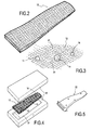
- L'invention sera mieux comprise et d'autres avantages de celle-ci apparaîtront plus clairement à la lumière de la description qui va suivre d'un procédé de fabrication d'une aube témoin conforme à son principe, donnée uniquement à titre d'exemple et faite en référence aux dessins annexés dans lesquels :
- la figure 1 illustre le tissage en trois dimensions de l'ébauche tridimensionnelle ;
- la figure 2 est une représentation schématique de l'ébauche ainsi obtenue ;
- la figure 3 illustre l'insertion des éléments en résine à l'état solide dans ladite ébauche ;
- la figure 4 illustre l'enrobage de l'ébauche par de la résine liquide injectée sous pression dans un moule ; et
- la figure 5 illustre l'aube témoin ainsi obtenue.
En se référant aux dessins, on a schématisé un procédé de fabrication d'une aube témoin comportant une phase de réalisation d'une ébauche tridimensionnelle tissée, en fibres de matériaux synthétiques, à l'aide d'un métier à tisser 11 schématisé à la figure 1. Une étape de ce genre a été décrite dansEP 1 526 285 et ne sera pas décrite à nouveau. L'invention s'applique néanmoins à tout type de tissage en trois dimensions susceptible de matérialiser une ébauche 12 comme celle de la figure 2. Les fibres utilisées sont de préférence des fibres de carbone. On pourrait aussi utiliser des fibres de verre ou d'aramide.
L'étape suivante, schématisée à la figure 3, consiste à insérer des éléments en résine 14 à l'état solide, ici des billes sphériques, à des emplacements choisis de l'ébauche. On établit parallèlement une cartographie de ces implantations tout en mémorisant les diamètres des billes insérées aux différents emplacements.
L'ébauche 12 ainsi traitée est placée dans un moule 16 comportant l'empreinte de l'aube témoin souhaitée, semblable dans sa forme et ses dimensions au type d'aube qui sera soumis au contrôle non destructif par tomographie. Puis de la résine à l'état liquide est injectée sous pression dans le moule. Ce dernier peut être chauffé à une température favorisant la polymérisation de la résine. La maîtrise de tous ces paramètres est à la portée de l'homme du métier.
A titre d'exemple, on peut utiliser une résine époxy (connue sous l'appellation PR 520) qui a été utilisée avec succès. De nombreuses autres résines thermodurcissables peuvent être utilisées, notamment d'autres résines époxy, des résines de polyester, des résines phénoliques, etc...
Pour la phase de moulage, on a retenu les conditions suivantes (nullement impératives) - injection de la résine à 165° avec un débit de 300 cm3/min pour le remplissage du moule ;
- pression d'injection comprise entre X et 17 bars ;
- cuisson à 180° pendant 2 h.
- Il est à noter que d'autres défauts peuvent être introduits dans la même ébauche avant injection de la résine liquide.
- Parmi ceux-ci, on peut notamment mentionner la rupture des torons, du tissage qui peut être perçu sur la tomographie. Pour concrétiser de tels défauts à des emplacements prédéterminés de l'aube témoin, il suffit de sectionner certains torons de fibres à des emplacements choisis, par exemple à l'aide de simple ciseaux et d'établir la cartographie de ces coupures. De telles coupures 20 sont illustrées schématiquement à la figure 3. On procède ensuite au moulage de la figure 4.
- L'aube témoin 22 obtenue après moulage est illustrée à la figure 5.
Claims (4)
- Procédé de fabrication d'une aube témoin en matériau composite pour étalonnage d'un contrôle radiologique d'aubes semblables, caractérisé en ce qu'il consiste à réaliser une ébauche tridimensionnelle (12) tissée en fibres de matériau synthétique, à introduire des éléments en résine (14) à l'état solide à des emplacements prédéterminés de ladite ébauche, à introduire ladite ébauche dans un moule et à injecter de la résine sous pression dans ledit moule pour obtenir ladite aube témoin.
- Procédé selon la revendication 1, caractérisé en ce que les éléments en résine (14) ont une forme sensiblement sphérique.
- Procédé selon la revendication 2, caractérisé en ce que lesdits éléments en résine (14), sphériques, ont des diamètres différents choisis, par exemple, compris entre 2 et 10 mm.
- Procédé selon l'une des revendications précédentes, caractérisé en ce qu'on sectionne (20) certains torons de fibres de ladite ébauche à des emplacements choisis, avant injection de la résine.
Applications Claiming Priority (1)
| Application Number | Priority Date | Filing Date | Title |
|---|---|---|---|
| FR0654540A FR2907706B1 (fr) | 2006-10-26 | 2006-10-26 | Procede de fabrication d'une aube temoin en materiau composite |
Publications (2)
| Publication Number | Publication Date |
|---|---|
| EP1920909A1 true EP1920909A1 (fr) | 2008-05-14 |
| EP1920909B1 EP1920909B1 (fr) | 2011-08-31 |
Family
ID=38109492
Family Applications (1)
| Application Number | Title | Priority Date | Filing Date |
|---|---|---|---|
| EP07119155A Active EP1920909B1 (fr) | 2006-10-26 | 2007-10-24 | Procédé de fabrication d'une aube témoin en materiau composite |
Country Status (7)
| Country | Link |
|---|---|
| US (1) | US8062570B2 (fr) |
| EP (1) | EP1920909B1 (fr) |
| JP (1) | JP5198033B2 (fr) |
| CN (1) | CN101169381B (fr) |
| CA (1) | CA2607239C (fr) |
| FR (1) | FR2907706B1 (fr) |
| RU (1) | RU2442128C2 (fr) |
Cited By (1)
| Publication number | Priority date | Publication date | Assignee | Title |
|---|---|---|---|---|
| WO2016151215A1 (fr) * | 2015-03-23 | 2016-09-29 | Snecma | Procédé de fabrication d'une aube témoin pour étalonnage d'un contrôle tomographique et aube témoin en résultant |
Families Citing this family (9)
| Publication number | Priority date | Publication date | Assignee | Title |
|---|---|---|---|---|
| CN102023171B (zh) * | 2010-11-12 | 2012-07-25 | 航天材料及工艺研究所 | 用ct值定量表征复合材料内部夹杂缺陷类型的无损检测方法 |
| FR2993191B1 (fr) * | 2012-07-16 | 2015-01-16 | Snecma | Procedes et systeme de decoupe |
| US9042516B2 (en) * | 2012-10-09 | 2015-05-26 | The Boeing Company | Nondestructive examination of structures having embedded particles |
| FR3015680B1 (fr) * | 2013-12-19 | 2016-01-15 | Snecma | Procede de caracterisation d'une piece |
| FR3100270B1 (fr) | 2019-08-28 | 2021-07-30 | Safran Aircraft Engines | Hybridation des fibres du renfort fibreux d’une aube de soufflante |
| CN111070730B (zh) * | 2020-01-03 | 2021-05-28 | 国电联合动力技术有限公司 | 一种风电叶片真空灌注方法 |
| FR3109821B1 (fr) * | 2020-05-04 | 2022-12-23 | Safran Aircraft Engines | Vérification du positionnement d’une préforme fibreuse dans une aube |
| RU2742540C1 (ru) * | 2020-08-24 | 2021-02-08 | федеральное государственное бюджетное образовательное учреждение высшего образования "Казанский национальный исследовательский технический универитет им. А.Н. Туполева - КАИ" | Способ проведения исследования клеевых соединений многослойной втулки несущего винта вертолета |
| CN117307500B (zh) * | 2023-11-28 | 2024-03-05 | 河北技投机械设备有限公司 | 渣浆泵远程数字化监控方法、终端、监控系统及介质 |
Citations (2)
| Publication number | Priority date | Publication date | Assignee | Title |
|---|---|---|---|---|
| US20040034298A1 (en) * | 2002-08-13 | 2004-02-19 | Scimed Life Systems, Inc. | Radiographic sizing tool |
| EP1526285A1 (fr) * | 2003-10-20 | 2005-04-27 | Snecma Moteurs | Aube de turbomachine, notamment aube de soufflante et son procédé de fabrication |
Family Cites Families (15)
| Publication number | Priority date | Publication date | Assignee | Title |
|---|---|---|---|---|
| US4022547A (en) * | 1975-10-02 | 1977-05-10 | General Electric Company | Composite blade employing biased layup |
| JPS59184647A (ja) * | 1983-04-04 | 1984-10-20 | ポリウレタン化成株式会社 | 熱成形可能な積層体 |
| JPH01223342A (ja) * | 1988-03-03 | 1989-09-06 | Kawasaki Heavy Ind Ltd | 非破壊検査用標準試験体の製造方法 |
| US5061542A (en) * | 1989-08-28 | 1991-10-29 | United Technologies Corporation | Stabilizing foam inserts for resin transfer molding |
| EP0415869B1 (fr) * | 1989-08-28 | 1996-07-24 | United Technologies Corporation | Stabilisation de pièces d'insertion pour le procédé "RTM" |
| JPH0712617B2 (ja) * | 1993-03-25 | 1995-02-15 | ヤマウチ株式会社 | 成形プレス用クッション材 |
| JP3403593B2 (ja) * | 1996-10-29 | 2003-05-06 | テルモ株式会社 | 測定用器具および該測定用器具を用いた測定方法 |
| US6041132A (en) * | 1997-07-29 | 2000-03-21 | General Electric Company | Computed tomography inspection of composite ply structure |
| DE19803909A1 (de) * | 1998-02-02 | 1999-08-05 | Ver Foerderung Inst Kunststoff | Verfahren zur Herstellung von endlosfaserverstärkten Hohlkörpern im Harzinjektionsverfahren |
| JP2971432B2 (ja) * | 1998-03-13 | 1999-11-08 | 川崎重工業株式会社 | 繊維強化プラスチック構造体の検査方法 |
| JP2001146691A (ja) * | 1999-08-27 | 2001-05-29 | Gabriela Tourosuman Jessica | ビーズを用いた衣類の装飾方法 |
| EP1473130B1 (fr) * | 2001-12-06 | 2011-08-24 | Toray Industries, Inc. | Materiau composite a fibres et son procede de production |
| CN1194848C (zh) * | 2002-10-09 | 2005-03-30 | 天津大学 | 三维编织纤维增强聚合物生物复合材料骨器件制造方法 |
| RU50314U1 (ru) * | 2005-04-15 | 2005-12-27 | Федеральное государственное унитарное предприятие "Всероссийский научно-исследовательский институт автоматики имени Н.Л. Духова" | Устройство для радиографии и томографии |
| FR2907707B1 (fr) * | 2006-10-26 | 2009-01-30 | Snecma Sa | Procede de fabrication d'une aube temoin en materiau composite |
-
2006
- 2006-10-26 FR FR0654540A patent/FR2907706B1/fr not_active Expired - Fee Related
-
2007
- 2007-10-22 US US11/876,278 patent/US8062570B2/en active Active
- 2007-10-23 CA CA2607239A patent/CA2607239C/fr active Active
- 2007-10-24 EP EP07119155A patent/EP1920909B1/fr active Active
- 2007-10-24 JP JP2007275995A patent/JP5198033B2/ja active Active
- 2007-10-25 RU RU2007139628/05A patent/RU2442128C2/ru active
- 2007-10-26 CN CN200710165533.5A patent/CN101169381B/zh active Active
Patent Citations (2)
| Publication number | Priority date | Publication date | Assignee | Title |
|---|---|---|---|---|
| US20040034298A1 (en) * | 2002-08-13 | 2004-02-19 | Scimed Life Systems, Inc. | Radiographic sizing tool |
| EP1526285A1 (fr) * | 2003-10-20 | 2005-04-27 | Snecma Moteurs | Aube de turbomachine, notamment aube de soufflante et son procédé de fabrication |
Non-Patent Citations (1)
| Title |
|---|
| PFEIFER: "Computed Tomography of Advanced Composite Materials", ADVANCED COMPOSITES, 4 December 1985 (1985-12-04), Dearborn, Michigan, USA, pages 177 - 188, XP008079948 * |
Cited By (3)
| Publication number | Priority date | Publication date | Assignee | Title |
|---|---|---|---|---|
| WO2016151215A1 (fr) * | 2015-03-23 | 2016-09-29 | Snecma | Procédé de fabrication d'une aube témoin pour étalonnage d'un contrôle tomographique et aube témoin en résultant |
| FR3034038A1 (fr) * | 2015-03-23 | 2016-09-30 | Snecma | Procede de fabrication d'une aube temoin pour etalonnage d'un controle tomographique et aube temoin en resultant |
| US11060986B2 (en) | 2015-03-23 | 2021-07-13 | Safran Aircraft Engines | Method of fabricating a reference blade for calibrating tomographic inspection, and a resulting reference blade |
Also Published As
| Publication number | Publication date |
|---|---|
| CA2607239C (fr) | 2014-06-03 |
| JP5198033B2 (ja) | 2013-05-15 |
| EP1920909B1 (fr) | 2011-08-31 |
| CN101169381B (zh) | 2012-07-04 |
| US20080099958A1 (en) | 2008-05-01 |
| RU2442128C2 (ru) | 2012-02-10 |
| JP2008107354A (ja) | 2008-05-08 |
| CN101169381A (zh) | 2008-04-30 |
| CA2607239A1 (fr) | 2008-04-26 |
| FR2907706B1 (fr) | 2009-02-06 |
| FR2907706A1 (fr) | 2008-05-02 |
| US8062570B2 (en) | 2011-11-22 |
| RU2007139628A (ru) | 2009-04-27 |
Similar Documents
| Publication | Publication Date | Title |
|---|---|---|
| EP1916092B1 (fr) | Procédé de fabrication d'une aube témoin en matériau composite | |
| EP1920909B1 (fr) | Procédé de fabrication d'une aube témoin en materiau composite | |
| EP3227076B1 (fr) | Procédé de controle de position d'une préforme dans un moule | |
| CA2879300C (fr) | Procede et systeme de decoupe d'une preforme destinee a la fabrication d'une piece de turbomachine | |
| WO1998008370A2 (fr) | Rotor de turbine composite | |
| FR3024959A1 (fr) | Procede et ensemble de fabrication d'aube composite | |
| WO2007125249A1 (fr) | Procede de realisation de strate fibreuse pour la fabrication d'une preforme de piece composite | |
| EP3827119A1 (fr) | Texture fibreuse pour carter en materiau composite a resistance a l'impact amelioree | |
| FR3111658A1 (fr) | Aube en matériau composite à renfort fibreux tissé tridimensionnel et peau tissée bidimensionnel et son procédé de fabrication | |
| FR2633213A1 (fr) | Procede de realisation d'une preforme fibreuse pour la fabrication de pieces en materiau composite ayant une forme complexe | |
| EP2199069B1 (fr) | Fabrication de pièces composites complexes | |
| EP3990263A1 (fr) | Piece de revolution en materiau composite ayant une resistance au delaminage amelioree | |
| JP2011088363A (ja) | 複合材ファンバイパスダクト及びその他の同様な構成要素を製作するための螺旋ワインディングシステム | |
| US10016946B2 (en) | Weaving method and apparatus for performing the same | |
| EP4523895A2 (fr) | Procédé de tressage de multi-mandrin | |
| FR3135096A1 (fr) | Metier a tisser du type jacquard pour la fabrication d’une preforme tissee | |
| WO2023275458A1 (fr) | Mise en forme reproductible d'une ebauche fibreuse | |
| FR3132915A1 (fr) | Toron destiné à la formation d’une préforme fibreuse d’une pièce en matériau composite |
Legal Events
| Date | Code | Title | Description |
|---|---|---|---|
| PUAI | Public reference made under article 153(3) epc to a published international application that has entered the european phase |
Free format text: ORIGINAL CODE: 0009012 |
|
| 17P | Request for examination filed |
Effective date: 20071024 |
|
| AK | Designated contracting states |
Kind code of ref document: A1 Designated state(s): AT BE BG CH CY CZ DE DK EE ES FI FR GB GR HU IE IS IT LI LT LU LV MC MT NL PL PT RO SE SI SK TR |
|
| AX | Request for extension of the european patent |
Extension state: AL BA HR MK RS |
|
| AKX | Designation fees paid |
Designated state(s): DE FR GB IT |
|
| GRAP | Despatch of communication of intention to grant a patent |
Free format text: ORIGINAL CODE: EPIDOSNIGR1 |
|
| RIC1 | Information provided on ipc code assigned before grant |
Ipc: B29C 70/48 20060101AFI20110127BHEP Ipc: B29C 70/54 20060101ALI20110127BHEP |
|
| GRAS | Grant fee paid |
Free format text: ORIGINAL CODE: EPIDOSNIGR3 |
|
| RTI1 | Title (correction) |
Free format text: METHOD OF PRODUCING A REFERENCE VANE FROM A COMPOSITE MATERIAL |
|
| GRAA | (expected) grant |
Free format text: ORIGINAL CODE: 0009210 |
|
| AK | Designated contracting states |
Kind code of ref document: B1 Designated state(s): DE FR GB IT |
|
| REG | Reference to a national code |
Ref country code: GB Ref legal event code: FG4D Free format text: NOT ENGLISH |
|
| REG | Reference to a national code |
Ref country code: DE Ref legal event code: R096 Ref document number: 602007016704 Country of ref document: DE Effective date: 20111103 |
|
| PLBE | No opposition filed within time limit |
Free format text: ORIGINAL CODE: 0009261 |
|
| STAA | Information on the status of an ep patent application or granted ep patent |
Free format text: STATUS: NO OPPOSITION FILED WITHIN TIME LIMIT |
|
| 26N | No opposition filed |
Effective date: 20120601 |
|
| REG | Reference to a national code |
Ref country code: DE Ref legal event code: R097 Ref document number: 602007016704 Country of ref document: DE Effective date: 20120601 |
|
| REG | Reference to a national code |
Ref country code: FR Ref legal event code: PLFP Year of fee payment: 9 |
|
| REG | Reference to a national code |
Ref country code: FR Ref legal event code: PLFP Year of fee payment: 10 |
|
| REG | Reference to a national code |
Ref country code: FR Ref legal event code: PLFP Year of fee payment: 11 |
|
| REG | Reference to a national code |
Ref country code: FR Ref legal event code: CD Owner name: SAFRAN AIRCRAFT ENGINES, FR Effective date: 20170719 |
|
| REG | Reference to a national code |
Ref country code: FR Ref legal event code: PLFP Year of fee payment: 12 |
|
| PGFP | Annual fee paid to national office [announced via postgrant information from national office to epo] |
Ref country code: DE Payment date: 20251020 Year of fee payment: 19 |
|
| PGFP | Annual fee paid to national office [announced via postgrant information from national office to epo] |
Ref country code: GB Payment date: 20251029 Year of fee payment: 19 |
|
| PGFP | Annual fee paid to national office [announced via postgrant information from national office to epo] |
Ref country code: IT Payment date: 20251031 Year of fee payment: 19 |
|
| PGFP | Annual fee paid to national office [announced via postgrant information from national office to epo] |
Ref country code: FR Payment date: 20251023 Year of fee payment: 19 |