EP1919430B1 - Compression device for a limb - Google Patents
Compression device for a limb Download PDFInfo
- Publication number
- EP1919430B1 EP1919430B1 EP06765067A EP06765067A EP1919430B1 EP 1919430 B1 EP1919430 B1 EP 1919430B1 EP 06765067 A EP06765067 A EP 06765067A EP 06765067 A EP06765067 A EP 06765067A EP 1919430 B1 EP1919430 B1 EP 1919430B1
- Authority
- EP
- European Patent Office
- Prior art keywords
- sleeve
- limb
- compression device
- compression
- pressure
- Prior art date
- Legal status (The legal status is an assumption and is not a legal conclusion. Google has not performed a legal analysis and makes no representation as to the accuracy of the status listed.)
- Active
Links
- 230000006835 compression Effects 0.000 title claims abstract description 69
- 238000007906 compression Methods 0.000 title claims abstract description 69
- 239000012530 fluid Substances 0.000 claims abstract description 23
- 230000001419 dependent effect Effects 0.000 claims description 8
- 238000012544 monitoring process Methods 0.000 claims description 7
- 238000000034 method Methods 0.000 claims description 6
- 238000001514 detection method Methods 0.000 claims description 4
- 230000008859 change Effects 0.000 claims description 2
- 210000003414 extremity Anatomy 0.000 description 50
- 208000005230 Leg Ulcer Diseases 0.000 description 8
- 210000002683 foot Anatomy 0.000 description 7
- 230000036541 health Effects 0.000 description 5
- 230000008901 benefit Effects 0.000 description 4
- 230000002265 prevention Effects 0.000 description 4
- 238000004891 communication Methods 0.000 description 3
- 238000002560 therapeutic procedure Methods 0.000 description 3
- 206010051055 Deep vein thrombosis Diseases 0.000 description 2
- 206010030113 Oedema Diseases 0.000 description 2
- 206010040943 Skin Ulcer Diseases 0.000 description 2
- 206010047249 Venous thrombosis Diseases 0.000 description 2
- 239000008280 blood Substances 0.000 description 2
- 210000004369 blood Anatomy 0.000 description 2
- 238000010586 diagram Methods 0.000 description 2
- 230000035876 healing Effects 0.000 description 2
- 230000009467 reduction Effects 0.000 description 2
- WHXSMMKQMYFTQS-UHFFFAOYSA-N Lithium Chemical compound [Li] WHXSMMKQMYFTQS-UHFFFAOYSA-N 0.000 description 1
- 238000007792 addition Methods 0.000 description 1
- 210000003423 ankle Anatomy 0.000 description 1
- 238000003287 bathing Methods 0.000 description 1
- 230000017531 blood circulation Effects 0.000 description 1
- 230000015556 catabolic process Effects 0.000 description 1
- 230000000694 effects Effects 0.000 description 1
- 230000000302 ischemic effect Effects 0.000 description 1
- 229910052744 lithium Inorganic materials 0.000 description 1
- 210000003141 lower extremity Anatomy 0.000 description 1
- 239000000463 material Substances 0.000 description 1
- 230000007246 mechanism Effects 0.000 description 1
- 230000002441 reversible effect Effects 0.000 description 1
- 208000019553 vascular disease Diseases 0.000 description 1
Images

Classifications
-
- A—HUMAN NECESSITIES
- A61—MEDICAL OR VETERINARY SCIENCE; HYGIENE
- A61H—PHYSICAL THERAPY APPARATUS, e.g. DEVICES FOR LOCATING OR STIMULATING REFLEX POINTS IN THE BODY; ARTIFICIAL RESPIRATION; MASSAGE; BATHING DEVICES FOR SPECIAL THERAPEUTIC OR HYGIENIC PURPOSES OR SPECIFIC PARTS OF THE BODY
- A61H9/00—Pneumatic or hydraulic massage
- A61H9/005—Pneumatic massage
- A61H9/0078—Pneumatic massage with intermittent or alternately inflated bladders or cuffs
-
- A—HUMAN NECESSITIES
- A61—MEDICAL OR VETERINARY SCIENCE; HYGIENE
- A61H—PHYSICAL THERAPY APPARATUS, e.g. DEVICES FOR LOCATING OR STIMULATING REFLEX POINTS IN THE BODY; ARTIFICIAL RESPIRATION; MASSAGE; BATHING DEVICES FOR SPECIAL THERAPEUTIC OR HYGIENIC PURPOSES OR SPECIFIC PARTS OF THE BODY
- A61H2205/00—Devices for specific parts of the body
- A61H2205/10—Leg
-
- Y—GENERAL TAGGING OF NEW TECHNOLOGICAL DEVELOPMENTS; GENERAL TAGGING OF CROSS-SECTIONAL TECHNOLOGIES SPANNING OVER SEVERAL SECTIONS OF THE IPC; TECHNICAL SUBJECTS COVERED BY FORMER USPC CROSS-REFERENCE ART COLLECTIONS [XRACs] AND DIGESTS
- Y10—TECHNICAL SUBJECTS COVERED BY FORMER USPC
- Y10S—TECHNICAL SUBJECTS COVERED BY FORMER USPC CROSS-REFERENCE ART COLLECTIONS [XRACs] AND DIGESTS
- Y10S601/00—Surgery: kinesitherapy
- Y10S601/20—Flexible membrane caused to be moved
Definitions
- This invention relates to a compression device for the limb and particularly to a device for use on the leg.
- the device may be used for compression therapy used in the treatment of venous leg ulcers.
- Compression therapy is used in the treatment of venous leg ulcers.
- the treatment relies on the compression achieving a reduction in oedema and improved return of blood via the venous system. This in turn reduces the residence time for blood supplied to the lower limb and the severity of ischaemic episodes within the limb that can result in tissue breakdown.
- Elastic bandages have the advantages that the patient can be mobile, can be treated at home and that once applied by a health care professional any removal or interference may be possible to detect.
- Elastic bandages do however have many disadvantages. They can work loose, the pressure generated by the bandage on the limb is not measured and depends on the level of skill of the health care professional applying the bandage, the level of compression is also affected by the circumference of the limb, the bandage cannot be removed and reapplied by the patient, for instance for bathing, and many patients find them unsightly, uncomfortable, hot or painful.
- Compression of the limb in the treatment of venous leg ulcers can also be achieved by the use of compression stockings, although they are most often used in the prevention of leg ulcers for instance in the prevention of recurrence after an active leg ulcer has healed.
- Compression stockings have many of the advantages of elastic bandages, they can be used at home and the patient can be mobile. They however have some disadvantages. They are difficult to apply as the narrow ankle part has to be pulled over the heel, compliance with treatment is difficult to monitor as the patient may be able to remove and replace the stocking themselves and patients can find them uncomfortable.
- Compression of the limb can also be achieved by a pneumatic compression device.
- a pneumatic compression device As venous leg ulcers are most usually treated at home or in the community and the known compression devices are large, heavy and require professional supervision, their adoption for such treatment has not been widespread.
- the pump which produces the compression is large and heavy and can supply fluid to the cuffs through many pipes. These characteristics make the known devices unsuitable for domestic use.
- Pneumatic compression devices have the following advantages: They provide an effective treatment; while deflated, the inflatable cuff or cuffs are easy to apply to the patient's leg; and the pressure is more readily controlled and monitored.
- a compression device for a limb of a patient comprising: an inflatable sleeve arranged to surround the limb, a conduit attached to the sleeve arranged to deliver fluid to the sleeve, a control system arranged to control flow of fluid in the device and a memory arranged to store gathered data relating to the duration of use of the device characterised in the device is arranged to detect whether the sleeve is in place surrounding the limb and the gathered data is dependent upon detection of whether the sleeve is in place surrounding the limb.
- Such a compression device allows direct monitoring of use of the device by, for example, a healthcare professional.
- a patient may only see a healthcare professional once or twice a week and this device provides the healthcare professional with independent knowledge of the usage details which the patient may otherwise be reluctant to provide or may not be able to provide accurately. Problems associated with cases of poor usage of the compression device can thus be more easily identified.
- control system comprises a pump and a controller unit.
- the device preferably further comprises a display device arranged to provide a display dependent upon the gathered data.
- the controller unit is portable and wearable and most preferably it is attached to the conduit.
- the controller unit preferably includes the display which may be in the form of an LCD screen. Alternatively, the display may be part of a remote device such as a personal computer with which the controller can communicate e.g. by cable connection or radio frequency or infrared communication.
- the device may comprise at least one pressure sensor arranged to measure the pressure exerted by the device.
- the sensors may be attached to the sleeve and located between the sleeve and the limb, the sensor(s) providing readings of the pressure experienced by the limb due to the inflation of the sleeve by the controller.
- the pressure sensor may be a contact pressure sensor.
- the predetermined compression profile may be selected by the health care professional to cater for the patient's condition. For example, a patient with lymphodema may require a different level of compression than a patient with a healed leg ulcer.
- the sensor also allows the device to increase or decrease the pressure on a particular part of the limb to give the predetermined compression profile while the device is in use. This alleviates the problem of pressure difference experienced with the use of elastic bandages where the pressure depends on the tension in the bandage, the amount of overlap and the shape of the leg of the patient.
- the pressure sensor may be used to measure the fluid pressure inside the sleeve thus providing a measure of the pressure exerted by the sleeve.
- the sleeve may have a valve associated with it and the control system be arranged to control operation of the valve and thereby inflation/deflation of the sleeve.
- the pressure sensors associated with the sleeve are preferably located between the valve and the sleeve.
- the pressure sensor is preferably a fluid pressure sensor arranged to measure fluid pressure preferably in the line between the valve and sleeve.
- the sleeve comprises one or more individually inflatable cells. More preferably a sensor is associated with each cell to monitor the pressure experienced by the limb due to pressure from that cell.
- each sleeve may have a valve associated with it and the controller is arranged to control operation of the valve and therefore inflation/deflation of each cell.
- the pressure sensors associated with each cell are preferably located between the valve and the cell. This allows the device to precisely control the pressure in each cell and thus comply with the predetermined compression profile. It also allows the device to operate an intermittent pneumatic compression.
- the memory is arranged to store data relating to the duration of use of the device and one more of the pressure exerted by the sleeve on the limb and the mode of operation of the device.
- the memory is arranged to store data relating to the use of the device while it is in place surrounding the limb.
- the control system must first determine whether or not the device is in place surrounding the limb. This may be achieved by having expected data values relating to use of the device stored in the memory for comparison by the control system with gathered data values. For example, when the sleeve is in place on the limb it will have a different inflation profile compared to when it is not in place surrounding the limb.
- the control system may monitor a change in pressure exerted by the sleeve as it is inflated, e.g. by monitoring the time taken to inflate the sleeve to a predetermined pressure, and this will vary depending upon whether or not the device is in place surrounding a limb. Therefore by comparing gathered data with expected time and pressure data values the controller can determine whether or not the sleeve is in place surrounding the limb.
- the control system may be arranged to disregard any data gathered when the sleeve is not in place around the limb and this provides more accurate, useful gathered data for analysis.
- the capability of the controller to deliver predetermined compression profiles to the limb also enables the health care professional to give the patient some control over their treatment.
- the patient can select a high compression or low compression setting. This alleviates the problem of non-compliance in some patients who cannot tolerate the pain of compression bandages or stockings that only provide one compression level.
- the use of the device on a low setting is preferable to rejection of the treatment altogether.
- the compression device may be for the limb of a mobile patient.
- the sleeve is low profile and discrete. This allows the patient to use the device wearing ordinary clothes and shoes.
- the sleeve comprises a leg cuff and a foot cuff both of which are low profile and discrete. More preferably the leg and foot cuffs are anatomically shaped to provide compression on those parts of the leg or foot which have the greatest effect on blood flow. This gives the advantage of reducing the overall size of the device and thus the profile of the cuff and size and power of the pump. Depending on the shape of the cuffs it can also reduce discomfort from pressure on bony areas of the limb.
- a method of monitoring use of a compression device for a limb of a patient having an inflatable sleeve arranged to surround the limb, a conduit attached to the sleeve arranged to deliver fluid to the sleeve and a control system arranged to control flow of fluid in the device including the step of storing gathered data relating to the duration of use of the device, characterised in that the device is arranged to detect whether the sleeve is in place surrounding the limb and the gathered data is dependent upon detection of wherther the sleeve is in place surrounding the limb.
- a data carrier carrying software which when run on a processor of a control system of a compression device is arranged to monitor use of the device according to the method of the second aspect of the invention.
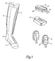
- FIG. 1 the compression device of the invention is shown on the leg of a patient in a standing position.
- the device comprises a sleeve 2 having a leg cuff 4 connected to a foot cuff 6.
- the device also comprises a control system housed within a controller unit 8.
- the sleeve 2 is connected to the controller unit 8 by a conduit 10.
- the controller unit 8 is a small, hand held unit that may be clipped to the sleeve or to the waistband of the patient's trousers or skirt.
- the controller unit 8 is battery powered, by a Lithium battery, and rechargeable so that it can be recharged on the base unit 12.
- the device also comprises an understocking 14 worn between the patient's leg and the sleeve 2.
- the understocking is present to absorb any moisture from the patient's leg but is not intended to apply compression.
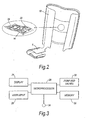
- the sleeve 2 has an inner 16 and an outer 18 surface composed of a durable flexible material that can be sponged clean and is divided into a plurality of cells 20 best seen in Figure 2 .
- the controller unit 8 comprises a display 21 in the form of an LCD panel. Additionally, the controller unit 8 comprises a user input in the form of a row of buttons 26. Referring to Figure 3 , the controller unit 8 comprises a microprocessor 28, and a memory 30. The control system also comprises a pump and valve arrangement 32. A pressure sensor 34 is attached to the sleeve and located between the sleeve and the limb and provides readings of the pressure experienced by the limb due to inflation of the sleeve by the control system. In this embodiment the pressure sensor 34 is a contact pressure sensor. The microprocessor 28 is able to read data from and write data to the memory. Operation of the control system by a user is achieved via the user input 26.
- the pressure sensor 34 provides information relating to the pressure exerted by the sleeve 2 on the limb.
- the microprocessor 28 is able to determine the length of time for which the sleeve 2 is inflated and in place surrounding the limb. This data is stored in the memory 30.
- the compression device operates in a continuous pressure mode. In this continuous pressure mode a patient or healthcare professional uses the buttons 26 to input a desired constant pressure which is required to be applied to the limb via the sleeve 2.
- the microprocessor 28 arranges for inflation of the sleeve 2 to the required pressure.
- the pressure sensor 34 is used to determine when the required pressure has been reached.
- the pressure being exerted by the sleeve 2 on the limb falls below a required level it is detected by the pressure sensor 34 and the microprocessor 28 communicates with the pump and valve 32 in order to inflate the sleeve 2 back up to the required level of pressure.
- the microprocessor 28 runs a timer programme to measure the length of time for which the pressure being applied by the sleeve is at a particular level. This data is stored in the memory 30. Using the user input buttons 26. the user can specify the length of time for which the sleeve should remain inflated. After this length of time has expired the microprocessor 28 arranges for deflation of the sleeve 2.
- the healthcare professional can request details of use of the device to be displayed on the LCD display screen 21, by, for example inputting a PIN number.
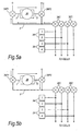
- Figure 4 shows a device according to a second embodiment of the invention where the leg cuff and foot cuff comprise cells with an anatomical shape 22.
- the leg cuff and foot cuff comprise cells with an anatomical shape 22.
- Four cells are provided in this embodiment.
- Each cell is provided with a sensor 34 located centrally in each cell but on the inside of the sleeve between the sleeve and the leg.
- the sleeve is marked on the outside at a position corresponding to the position of the sensor 34 in the inside of the sleeve at 24.
- the foot cuff in either embodiment may have a sensor located in a position corresponding to the instep of the foot.
- the control system associated with the device according to the second embodiment is similar to the control system of the device according to the first embodiment except that there are four contact pressure sensors 34 instead of only one contact pressure sensor.
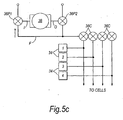
- the pump and valve arrangement 32 of the device of this embodiment includes six valves 36 and a pump 38 controlled by the microprocessor 28.
- the pump 38 has an inlet I and an outlet O and, together with an inlet valve 36P1 and an outlet valve 36P2, controls the air pressure in a fluid feedline F.
- the other valves are cell valves 36C associated with each cell and arranged to control the flow of air between the cell and the fluid feedline F.
- the 36P2 each have a port connected to atmosphere and a port connected to the feedline F in addition to a port connected to the pump inlet or outlet.
- the pump valve 36P1 is able to connect the pump inlet I to the feedline F or to atmosphere.
- the pump valve 36P2 is able to connect the pump outlet O to the feedline F or to the atmosphere.
- the microprocessor 28 is able to provide instructions to the pump and valves such that the pump can be used to selectively inflate or deflate any one or more of the cells. This is achieved by selectively operating the pump valves 36P1, 36P2 to control direction of air flow to or from the fluid feedline F and controlling the cell valves 36C which are selectively opened or closed to allow flow of air to and from the individual cells.
- the pressure sensors 34 are contact pressure sensors located on the surface of the sleeve.
- the pump 38 is non-reversible and operates to pump air in a direction from its inlet I to its outlet O.
- the pump inlet valve 36P1 is arranged to connect the pump inlet I to the fluid line F by the microprocessor 28 and the pump outlet valve 36P2 is arranged to connect the pump outlet to atmosphere.
- This operation of the valves 36P1, 36P2 causes the air within the pump and valve arrangement to flow in the direction indicated by the arrows of Figure 5a . Therefore air is pumped away from the cells.
- Each one of the cell valves 36C can be operated individually under instruction from the microprocessor 28 so that air may be drawn from one or more cells without being drawn from the other cells.
- the first pump valve 36P1 when it is desired to pump air to the cells, the first pump valve 36P1 is arranged to connect the pump inlet I to atmosphere and the second pump valve 36P2 is arranged to connect the pump outlet O to the feed line F. Operation of the pump then causes air to flow in the direction of the arrows shown in Figure 5b i.e. air is pumped towards the cells 22.
- the cell valves 36C can be individually operated by the microprocessor 28 so that any one or more cells may be pumped up selectively.
- both pump valves 36P1 and 36P2 are arranged to connect the pump to atmosphere so that the fluid in the feedline F is at atmospheric pressure.
- the pump does not operate and the air pressure inside the cells remains unchanged.
- the device of the second embodiment is able to be selectively operated in a different mode to that previously described for the first embodiment.
- the device can also be operated in the same mode as previously described.
- the device can be used to provide intermittent pneumatic compression in which each of the cells is inflated in sequence e.g. from the bottom of the leg upwards.
- Compliance data i.e. data relating to use of the device, can be gathered by the processor 28 and stored in the memory 30.
- the healthcare professional can request that the gathered data stored in the memory 30 is displayed upon the display 21.
- the display 21 is not part of the controller. Instead, the controller unit can communicate via infrared communication with a remote display screen (not shown).
- the displayed data includes data relating to the length of time for which each cell has been inflated while surrounding the limb at a particular pressure and in a particular mode e.g. continuous constant pressure mode or intermittent pneumatic compression mode.
- the displayed data can also include data relating to the number of times which a patient has used the compression device within a set period e.g. within the last week, two weeks, since the last visit by the healthcare professional.
- the data can also include data relating to the actual time of day at which the compression device is used by a patient.
- the display data can also be analysed and a display provided to indicate whether or not the compliance by the patient is good or bad. There may be a set threshhold of use above which the compliance is good and below which it is bad.
- the displayed data which is available to the patient may be different to the displayed data which is available to the healthcare professional - the healthcare professional may have access to more information upon entry of a password using the user input.
- the healthcare professional uses the user input 26, it is possible for the healthcare professional to reset some or all of the data stored in the memory. This can be desirable between the visits of a healthcare professional to a patient for example.
- the healthcare professional may be required to enter a password using the user input 26 before data stored in the memory 30 can be erased.
- the memory 30 can also store data on the date of the last reset. Thus for instance if the patient resets the memory the date is recorded and at next visit the healthcare professional is presented with the reset date and the data collected since the reset.
- a range of standard or expected inflation times are stored on the memory 30. Therefore if the sleeve 2 is inflated while not in place on the limb then the microprocessor 28 will recognise this by comparing data gathered from the pressure sensors 34 with data stored in the memory 30. For example, the time taken to reach a predetermined pressure value can be measured and if it does not fall within an expected range then the microprocessor 28 recognises that the sleeve is not in place on the limb and causes the pump and valve arrangement 32 to cease inflating the sleeve and to deflate it instead. Data gathered by the sensors 34 whilst the sleeve 2 is not in place on the limb can also be discarded.
- the microprocessor can therefore determine, when the sleeve is inflated, whether it is in place on the patient's limb or not. This ensures that data collected and stored relating to use of the device can accurately reflect correct use of the device when it is in place, and not be affected by inflation of the sleeve when the device is not in place on the patient.
- a microprocessor 28 can recognise if the pump and valve arrangement is attempting to inflate the sleeve 2 but the pressure measured by one or more of the pressure sensors 34 is not increasing correspondingly. In this situation the microprocessor 28 recognises that the sleeve 2 has a puncture and a suitable error message can be displayed on the display 21 to inform the user that there is a puncture in said one or more of the cells 22.
- the intermittent pneumatic compression mode may be selectively available with a device substantially identical to the device of the first embodiment.
- the, or each, sensor may be a contact sensor, a pressure sensor or any other suitable type of sensor. Where more than one sensor is provided, combinations of different types of sensor may be used.
- the contact pressure sensors of the second embodiment may be replaced by air pressure sensors located in the line between the cell and its associated valve 36. The sensor may be situated in the controller unit 8.
- the controller unit 8 may not have a user input 26. Instead, for example, the system may receive inputs from e.g. a keyboard of a PC or other processing device when it is in communication (e.g. infra-red) with it.
- a keyboard of a PC or other processing device when it is in communication (e.g. infra-red) with it.
Applications Claiming Priority (2)
| Application Number | Priority Date | Filing Date | Title |
|---|---|---|---|
| GBGB0515040.4A GB0515040D0 (en) | 2005-07-21 | 2005-07-21 | Compression device for the limb |
| PCT/GB2006/002738 WO2007010278A1 (en) | 2005-07-21 | 2006-07-20 | Compression device for a limb |
Publications (2)
| Publication Number | Publication Date |
|---|---|
| EP1919430A1 EP1919430A1 (en) | 2008-05-14 |
| EP1919430B1 true EP1919430B1 (en) | 2011-08-24 |
Family
ID=34976355
Family Applications (1)
| Application Number | Title | Priority Date | Filing Date |
|---|---|---|---|
| EP06765067A Active EP1919430B1 (en) | 2005-07-21 | 2006-07-20 | Compression device for a limb |
Country Status (15)
| Country | Link |
|---|---|
| US (1) | US7909786B2 (ja) |
| EP (1) | EP1919430B1 (ja) |
| JP (1) | JP5031743B2 (ja) |
| CN (1) | CN101267793B (ja) |
| AT (1) | ATE521322T1 (ja) |
| AU (1) | AU2006271380B2 (ja) |
| CA (1) | CA2616145C (ja) |
| DK (1) | DK1919430T3 (ja) |
| ES (1) | ES2369935T3 (ja) |
| GB (1) | GB0515040D0 (ja) |
| MX (1) | MX2008000813A (ja) |
| NZ (1) | NZ565187A (ja) |
| PT (1) | PT1919430E (ja) |
| TW (1) | TWI392489B (ja) |
| WO (1) | WO2007010278A1 (ja) |
Families Citing this family (82)
| Publication number | Priority date | Publication date | Assignee | Title |
|---|---|---|---|---|
| TWI376221B (en) * | 2005-06-08 | 2012-11-11 | Convatec Technologies Inc | Compression device for the foot |
| US9642759B2 (en) | 2007-04-13 | 2017-05-09 | Stryker Corporation | Patient support with universal energy supply system |
| US8182437B2 (en) | 2007-05-08 | 2012-05-22 | Wright Therapy Products, Inc. | Pneumatic compression therapy system and methods of using same |
| EP2162109A4 (en) | 2007-06-20 | 2012-10-03 | Remo Moomiaie-Qajar | PORTABLE COMPRESSION DEVICE |
| US20090204037A1 (en) * | 2008-02-12 | 2009-08-13 | Sundaram Ravikumar | Compression Apparatus for Applying Intermittent Pressure to the Leg |
| US7969315B1 (en) | 2008-05-28 | 2011-06-28 | MedHab, LLC | Sensor device and method for monitoring physical stresses placed upon a user |
| US8384551B2 (en) * | 2008-05-28 | 2013-02-26 | MedHab, LLC | Sensor device and method for monitoring physical stresses placed on a user |
| US20100042028A1 (en) * | 2008-08-14 | 2010-02-18 | Albahealth, LLC | Foot wrap with inflatable bladder |
| US8177734B2 (en) * | 2008-09-30 | 2012-05-15 | Tyco Healthcare Group Lp | Portable controller unit for a compression device |
| US8535253B2 (en) | 2008-09-30 | 2013-09-17 | Covidien Lp | Tubeless compression device |
| WO2010065609A2 (en) * | 2008-12-02 | 2010-06-10 | Eddy Patrick E | Compression device and control system for applying pressure to a limb of a living being |
| US8162869B2 (en) * | 2009-07-10 | 2012-04-24 | Tyco Healthcare Group Lp | Hybrid compression garmet |
| US8752220B2 (en) * | 2009-07-10 | 2014-06-17 | Hill-Rom Services, Inc. | Systems for patient support, monitoring and treatment |
| US8257289B2 (en) * | 2010-02-03 | 2012-09-04 | Tyco Healthcare Group Lp | Fitting of compression garment |
| US8394043B2 (en) | 2010-02-12 | 2013-03-12 | Covidien Lp | Compression garment assembly |
| US20120065561A1 (en) * | 2010-09-03 | 2012-03-15 | Epoch Medical Innovations, Inc. | Device, system, and method for the treatment, prevention and diagnosis of chronic venous insufficiency, deep vein thrombosis, lymphedema and other circulatory conditions |
| US8753300B2 (en) | 2010-09-29 | 2014-06-17 | Covidien Lp | Compression garment apparatus having baseline pressure |
| US8758282B2 (en) | 2010-09-29 | 2014-06-24 | Covidien Lp | Compression garment apparatus having support bladder |
| US20120083712A1 (en) | 2010-09-30 | 2012-04-05 | Tyco Healthcare Group Lp | Monitoring Compliance Using Venous Refill Detection |
| US9453772B2 (en) | 2011-03-24 | 2016-09-27 | MedHab, LLC | Method of manufacturing a sensor insole |
| US10004946B2 (en) | 2011-03-24 | 2018-06-26 | MedHab, LLC | System and method for monitoring power applied to a bicycle |
| US10813825B2 (en) * | 2011-06-14 | 2020-10-27 | Portable Therapeutix, LLC | Compression device |
| US9114054B2 (en) | 2011-07-24 | 2015-08-25 | Oakwell Distribution, Inc. | System for monitoring the use of medical devices |
| US9125787B2 (en) | 2011-09-30 | 2015-09-08 | Covidien Lp | Compression garment having a foam layer |
| US9737454B2 (en) | 2012-03-02 | 2017-08-22 | Hill-Rom Services, Inc. | Sequential compression therapy compliance monitoring systems and methods |
| US20130231596A1 (en) * | 2012-03-02 | 2013-09-05 | David W. Hornbach | Sequential compression therapy compliance monitoring systems & methods |
| AU2013232352B2 (en) | 2012-03-12 | 2017-10-12 | Tactile Systems Technology, Inc. | Compression therapy device with multiple simultaneously active chambers |
| US9889063B2 (en) * | 2012-06-11 | 2018-02-13 | Wright Therapy Products, Inc. | Methods and systems for determining use compliance of a compression therapy device |
| DE102012013534B3 (de) | 2012-07-05 | 2013-09-19 | Tobias Sokolowski | Vorrichtung für repetitive Nervenstimulation zum Abbau von Fettgewebe mittels induktiver Magnetfelder |
| CA2882299C (en) | 2012-08-18 | 2023-09-19 | Wright Therapy Products, Inc. | Methods for determining the size of body parts as part of compression therapy procedures |
| US9872812B2 (en) | 2012-09-28 | 2018-01-23 | Kpr U.S., Llc | Residual pressure control in a compression device |
| US9402779B2 (en) | 2013-03-11 | 2016-08-02 | Covidien Lp | Compression garment with perspiration relief |
| US10058475B2 (en) * | 2013-03-15 | 2018-08-28 | Innovamed Health, LLC | Portable intermittent pneumatic compression system |
| CN103239340B (zh) * | 2013-05-16 | 2015-01-07 | 四川旭康医疗电器有限公司 | 一种感觉康复训练系统 |
| GB2514587A (en) | 2013-05-30 | 2014-12-03 | Vibrant Medical Ltd | Treatment of peripheral arterial disease and other conditions, and apparatus therefor |
| US9615992B2 (en) * | 2013-07-30 | 2017-04-11 | Lockheed Martin Corporation | System and method for supplementing circulation in a body |
| US20150057585A1 (en) * | 2013-08-20 | 2015-02-26 | Covidien Lp | Compression device having compliance tracking |
| JP6041774B2 (ja) * | 2013-09-06 | 2016-12-14 | 日東工器株式会社 | 浮腫重症度測定器 |
| US9295605B2 (en) | 2013-12-02 | 2016-03-29 | Wright Therapy Products, Inc. | Methods and systems for auto-calibration of a pneumatic compression device |
| US10470967B2 (en) | 2014-01-20 | 2019-11-12 | Tactile Systems Technology, Inc. | Bespoke compression therapy device |
| US10292894B2 (en) | 2014-02-11 | 2019-05-21 | Tactile Systems Technology, Inc. | Compression therapy device and compression therapy protocols |
| JP6012015B2 (ja) * | 2014-03-13 | 2016-10-25 | パナソニックIpマネジメント株式会社 | エアーマッサージ装置、および、その補助具 |
| US20150297100A1 (en) * | 2014-04-18 | 2015-10-22 | Hilario Castillo | Vital Socks |
| US20160120733A1 (en) * | 2014-10-30 | 2016-05-05 | Elwha Llc | Garment system including at least one sensor and at least one actuator responsive to the sensor and related methods |
| US9687404B2 (en) | 2014-08-26 | 2017-06-27 | Elwha Llc | Garment system including at least one muscle or joint activity sensor and at least one actuator responsive to the sensor and related methods |
| US20160120734A1 (en) * | 2014-10-30 | 2016-05-05 | Elwha Llc | Garment system including at least one sensor and at least one actuator responsive to the sensor and related methods |
| US11638676B2 (en) * | 2014-08-26 | 2023-05-02 | Ventrk, Llc | Garment system including at least one sensor and at least one actuator responsive to the sensor and related methods |
| US10456604B2 (en) | 2014-08-26 | 2019-10-29 | Elwha Llc | Garment system including at least one therapeutic stimulation delivery device and related methods |
| US10668305B2 (en) | 2014-08-26 | 2020-06-02 | Elwha Llc | Garment system including at least one therapeutic stimulation delivery device and related methods |
| US10232165B2 (en) | 2015-01-29 | 2019-03-19 | Elwha Llc | Garment system including at least one sensor and at least one actuator responsive to the sensor and related methods |
| US11491342B2 (en) | 2015-07-01 | 2022-11-08 | Btl Medical Solutions A.S. | Magnetic stimulation methods and devices for therapeutic treatments |
| US10695575B1 (en) | 2016-05-10 | 2020-06-30 | Btl Medical Technologies S.R.O. | Aesthetic method of biological structure treatment by magnetic field |
| US20180001107A1 (en) | 2016-07-01 | 2018-01-04 | Btl Holdings Limited | Aesthetic method of biological structure treatment by magnetic field |
| US11266850B2 (en) | 2015-07-01 | 2022-03-08 | Btl Healthcare Technologies A.S. | High power time varying magnetic field therapy |
| ES2797692T3 (es) | 2015-10-09 | 2020-12-03 | Kpr Us Llc | Cumplimiento con prenda de compresión |
| US11253717B2 (en) | 2015-10-29 | 2022-02-22 | Btl Healthcare Technologies A.S. | Aesthetic method of biological structure treatment by magnetic field |
| US10667984B2 (en) | 2015-12-18 | 2020-06-02 | Stryker Corporation | Systems and methods for operating patient therapy devices |
| US11141105B2 (en) * | 2016-03-11 | 2021-10-12 | Respiratory Technology Corporation | Long-term therapeutic pressure applicator and real-time monitoring system |
| CA3021991A1 (en) | 2016-04-27 | 2017-11-02 | Radial Medical, Inc. | Adaptive compression therapy systems and methods |
| US11464993B2 (en) | 2016-05-03 | 2022-10-11 | Btl Healthcare Technologies A.S. | Device including RF source of energy and vacuum system |
| US11247039B2 (en) | 2016-05-03 | 2022-02-15 | Btl Healthcare Technologies A.S. | Device including RF source of energy and vacuum system |
| US11534619B2 (en) | 2016-05-10 | 2022-12-27 | Btl Medical Solutions A.S. | Aesthetic method of biological structure treatment by magnetic field |
| US10583287B2 (en) | 2016-05-23 | 2020-03-10 | Btl Medical Technologies S.R.O. | Systems and methods for tissue treatment |
| CN108186327A (zh) * | 2016-06-08 | 2018-06-22 | 武汉佰起科技有限公司 | 一种医用熏洗仪 |
| US10556122B1 (en) | 2016-07-01 | 2020-02-11 | Btl Medical Technologies S.R.O. | Aesthetic method of biological structure treatment by magnetic field |
| US11504293B2 (en) * | 2016-11-08 | 2022-11-22 | Lear Corporation | Seat assembly having massage bladders with reduced pressure sensor count |
| US20180229048A1 (en) * | 2017-02-15 | 2018-08-16 | Btl Holdings Limited | Method and device for body fluid stimulation |
| US11410771B2 (en) | 2017-06-01 | 2022-08-09 | Stryker Corporation | Patient care devices with open communication |
| US10434033B2 (en) | 2017-11-01 | 2019-10-08 | Vena Group, LLC | Portable, reusable, and disposable intermittent pneumatic compression system |
| CA3084471A1 (en) | 2017-11-06 | 2019-05-09 | Tactile Systems Technology, Inc. | Compression garment systems |
| FR3081704B1 (fr) * | 2018-05-31 | 2023-11-17 | Neuraltide | Vetement d’application de pression |
| US20210069056A1 (en) * | 2018-05-31 | 2021-03-11 | Neuraltide | Pressure application method |
| US10893998B2 (en) | 2018-10-10 | 2021-01-19 | Inova Labs Inc. | Compression apparatus and systems for circulatory disorders |
| US10646233B1 (en) | 2018-11-28 | 2020-05-12 | Jay Dean Everett | Device, system and method for intermittent displacement of blood to mitigate peripheral nerve neuropathy |
| KR102192619B1 (ko) * | 2018-12-07 | 2020-12-17 | 순천향대학교 산학협력단 | 에어셀이 내장된 압박스타킹 |
| CN117771550A (zh) | 2019-04-11 | 2024-03-29 | 比特乐医疗方案股份有限公司 | 用于向患者的身体区域提供时变磁场和射频场的装置 |
| US11878167B2 (en) | 2020-05-04 | 2024-01-23 | Btl Healthcare Technologies A.S. | Device and method for unattended treatment of a patient |
| MX2022013485A (es) | 2020-05-04 | 2022-11-30 | Btl Healthcare Tech A S | Dispositivo y metodo para el tratamiento sin atencion del paciente. |
| WO2022098308A1 (en) * | 2020-11-05 | 2022-05-12 | National University Hospital (Singapore) Pte Ltd | Portable limb compression system |
| WO2023063864A1 (en) * | 2021-10-11 | 2023-04-20 | Arjo IP Holding Aktiebolag | A control unit, system and method for analyzing usage of compression therapy |
| US11896816B2 (en) | 2021-11-03 | 2024-02-13 | Btl Healthcare Technologies A.S. | Device and method for unattended treatment of a patient |
| USD971267S1 (en) | 2022-01-03 | 2022-11-29 | Therabody, Inc. | Controller for pneumatic compression device |
Family Cites Families (14)
| Publication number | Priority date | Publication date | Assignee | Title |
|---|---|---|---|---|
| US4396010A (en) * | 1980-06-30 | 1983-08-02 | The Kendall Company | Sequential compression device |
| US5807075A (en) * | 1993-11-23 | 1998-09-15 | Sarcos, Inc. | Disposable ambulatory microprocessor controlled volumetric pump |
| JPH07250873A (ja) * | 1994-03-14 | 1995-10-03 | Tec Corp | 血行促進器 |
| US6786879B1 (en) * | 1994-04-05 | 2004-09-07 | Kci Licensing, Inc. | Gradient sequential compression system for preventing deep vein thrombosis |
| US5575762A (en) * | 1994-04-05 | 1996-11-19 | Beiersdorf-Jobst, Inc. | Gradient sequential compression system and method for reducing the occurrence of deep vein thrombosis |
| US5591200A (en) * | 1994-06-17 | 1997-01-07 | World, Inc. | Method and apparatus for applying pressure to a body limb for treating edema |
| US5843007A (en) * | 1996-04-29 | 1998-12-01 | Mcewen; James Allen | Apparatus and method for periodically applying a pressure waveform to a limb |
| US6387065B1 (en) * | 1996-09-30 | 2002-05-14 | Kinetic Concepts, Inc. | Remote controllable medical pumping apparatus |
| US6494852B1 (en) * | 1998-03-11 | 2002-12-17 | Medical Compression Systems (Dbn) Ltd. | Portable ambulant pneumatic compression system |
| JP2000334011A (ja) * | 1999-05-27 | 2000-12-05 | Family Kk | マッサージ機及びマッサージ情報を記録した記録媒体 |
| JP2002065780A (ja) * | 2000-08-28 | 2002-03-05 | Matsushita Electric Works Ltd | マッサージ機 |
| JP2004535844A (ja) * | 2001-01-12 | 2004-12-02 | ミッドタウン・テクノロジー・リミテッド | 膨張可能なマッサージ装着衣料具 |
| US6926617B2 (en) * | 2002-03-15 | 2005-08-09 | Sri Sports Limited | Golf club shaft |
| US20040111048A1 (en) * | 2002-12-04 | 2004-06-10 | Jensen Jeffrey L. | Compression device for treatment of chronic venous insufficiency |
-
2005
- 2005-07-21 GB GBGB0515040.4A patent/GB0515040D0/en not_active Ceased
-
2006
- 2006-07-20 NZ NZ565187A patent/NZ565187A/en not_active IP Right Cessation
- 2006-07-20 DK DK06765067.1T patent/DK1919430T3/da active
- 2006-07-20 PT PT06765067T patent/PT1919430E/pt unknown
- 2006-07-20 AU AU2006271380A patent/AU2006271380B2/en not_active Ceased
- 2006-07-20 TW TW095126877A patent/TWI392489B/zh not_active IP Right Cessation
- 2006-07-20 ES ES06765067T patent/ES2369935T3/es active Active
- 2006-07-20 WO PCT/GB2006/002738 patent/WO2007010278A1/en active Application Filing
- 2006-07-20 JP JP2008522064A patent/JP5031743B2/ja not_active Expired - Fee Related
- 2006-07-20 CN CN2006800340740A patent/CN101267793B/zh not_active Expired - Fee Related
- 2006-07-20 CA CA2616145A patent/CA2616145C/en active Active
- 2006-07-20 AT AT06765067T patent/ATE521322T1/de active
- 2006-07-20 MX MX2008000813A patent/MX2008000813A/es active IP Right Grant
- 2006-07-20 EP EP06765067A patent/EP1919430B1/en active Active
- 2006-07-21 US US11/459,036 patent/US7909786B2/en active Active
Also Published As
| Publication number | Publication date |
|---|---|
| CA2616145C (en) | 2014-07-08 |
| WO2007010278A1 (en) | 2007-01-25 |
| GB0515040D0 (en) | 2005-08-31 |
| US7909786B2 (en) | 2011-03-22 |
| PT1919430E (pt) | 2011-10-19 |
| ATE521322T1 (de) | 2011-09-15 |
| CN101267793A (zh) | 2008-09-17 |
| AU2006271380A1 (en) | 2007-01-25 |
| US20070049853A1 (en) | 2007-03-01 |
| JP2009501594A (ja) | 2009-01-22 |
| EP1919430A1 (en) | 2008-05-14 |
| CA2616145A1 (en) | 2007-01-25 |
| MX2008000813A (es) | 2008-03-18 |
| AU2006271380B2 (en) | 2011-09-22 |
| JP5031743B2 (ja) | 2012-09-26 |
| NZ565187A (en) | 2011-01-28 |
| CN101267793B (zh) | 2012-07-04 |
| TWI392489B (zh) | 2013-04-11 |
| DK1919430T3 (da) | 2011-10-17 |
| ES2369935T3 (es) | 2011-12-09 |
| TW200716074A (en) | 2007-05-01 |
Similar Documents
| Publication | Publication Date | Title |
|---|---|---|
| EP1919430B1 (en) | Compression device for a limb | |
| EP1983962B1 (en) | Pressurised medical device | |
| EP3102172B1 (en) | A portable compression device | |
| JP6316831B2 (ja) | 圧迫治療に使用する監視システム | |
| WO2022245785A1 (en) | Systems and methods for determining physical shape properties of a limb during therapy and fit of a compression garment | |
| MX2008009134A (es) | Dispositivo medico presurizado | |
| CN110236910A (zh) | 微循环障碍智能诊疗仪及其使用方法、数据采集方法 | |
| NZ722357B2 (en) | A portable compression device |
Legal Events
| Date | Code | Title | Description |
|---|---|---|---|
| PUAI | Public reference made under article 153(3) epc to a published international application that has entered the european phase |
Free format text: ORIGINAL CODE: 0009012 |
|
| 17P | Request for examination filed |
Effective date: 20080206 |
|
| AK | Designated contracting states |
Kind code of ref document: A1 Designated state(s): AT BE BG CH CY CZ DE DK EE ES FI FR GB GR HU IE IS IT LI LT LU LV MC NL PL PT RO SE SI SK TR |
|
| 17Q | First examination report despatched |
Effective date: 20080930 |
|
| GRAP | Despatch of communication of intention to grant a patent |
Free format text: ORIGINAL CODE: EPIDOSNIGR1 |
|
| RAP1 | Party data changed (applicant data changed or rights of an application transferred) |
Owner name: CONVATEC TECHNOLOGIES INC. |
|
| GRAS | Grant fee paid |
Free format text: ORIGINAL CODE: EPIDOSNIGR3 |
|
| GRAA | (expected) grant |
Free format text: ORIGINAL CODE: 0009210 |
|
| AK | Designated contracting states |
Kind code of ref document: B1 Designated state(s): AT BE BG CH CY CZ DE DK EE ES FI FR GB GR HU IE IS IT LI LT LU LV MC NL PL PT RO SE SI SK TR |
|
| REG | Reference to a national code |
Ref country code: GB Ref legal event code: FG4D |
|
| REG | Reference to a national code |
Ref country code: CH Ref legal event code: NV Representative=s name: BOVARD AG Ref country code: CH Ref legal event code: EP |
|
| REG | Reference to a national code |
Ref country code: IE Ref legal event code: FG4D |
|
| REG | Reference to a national code |
Ref country code: DK Ref legal event code: T3 |
|
| REG | Reference to a national code |
Ref country code: PT Ref legal event code: SC4A Free format text: AVAILABILITY OF NATIONAL TRANSLATION Effective date: 20111013 |
|
| REG | Reference to a national code |
Ref country code: DE Ref legal event code: R096 Ref document number: 602006024033 Country of ref document: DE Effective date: 20111020 |
|
| REG | Reference to a national code |
Ref country code: NL Ref legal event code: T3 |
|
| REG | Reference to a national code |
Ref country code: SE Ref legal event code: TRGR |
|
| REG | Reference to a national code |
Ref country code: ES Ref legal event code: FG2A Ref document number: 2369935 Country of ref document: ES Kind code of ref document: T3 Effective date: 20111209 |
|
| LTIE | Lt: invalidation of european patent or patent extension |
Effective date: 20110824 |
|
| PG25 | Lapsed in a contracting state [announced via postgrant information from national office to epo] |
Ref country code: LT Free format text: LAPSE BECAUSE OF FAILURE TO SUBMIT A TRANSLATION OF THE DESCRIPTION OR TO PAY THE FEE WITHIN THE PRESCRIBED TIME-LIMIT Effective date: 20110824 Ref country code: IS Free format text: LAPSE BECAUSE OF FAILURE TO SUBMIT A TRANSLATION OF THE DESCRIPTION OR TO PAY THE FEE WITHIN THE PRESCRIBED TIME-LIMIT Effective date: 20111224 |
|
| PG25 | Lapsed in a contracting state [announced via postgrant information from national office to epo] |
Ref country code: PL Free format text: LAPSE BECAUSE OF FAILURE TO SUBMIT A TRANSLATION OF THE DESCRIPTION OR TO PAY THE FEE WITHIN THE PRESCRIBED TIME-LIMIT Effective date: 20110824 Ref country code: LV Free format text: LAPSE BECAUSE OF FAILURE TO SUBMIT A TRANSLATION OF THE DESCRIPTION OR TO PAY THE FEE WITHIN THE PRESCRIBED TIME-LIMIT Effective date: 20110824 Ref country code: CY Free format text: LAPSE BECAUSE OF FAILURE TO SUBMIT A TRANSLATION OF THE DESCRIPTION OR TO PAY THE FEE WITHIN THE PRESCRIBED TIME-LIMIT Effective date: 20110824 Ref country code: GR Free format text: LAPSE BECAUSE OF FAILURE TO SUBMIT A TRANSLATION OF THE DESCRIPTION OR TO PAY THE FEE WITHIN THE PRESCRIBED TIME-LIMIT Effective date: 20111125 Ref country code: SI Free format text: LAPSE BECAUSE OF FAILURE TO SUBMIT A TRANSLATION OF THE DESCRIPTION OR TO PAY THE FEE WITHIN THE PRESCRIBED TIME-LIMIT Effective date: 20110824 |
|
| PG25 | Lapsed in a contracting state [announced via postgrant information from national office to epo] |
Ref country code: SK Free format text: LAPSE BECAUSE OF FAILURE TO SUBMIT A TRANSLATION OF THE DESCRIPTION OR TO PAY THE FEE WITHIN THE PRESCRIBED TIME-LIMIT Effective date: 20110824 Ref country code: CZ Free format text: LAPSE BECAUSE OF FAILURE TO SUBMIT A TRANSLATION OF THE DESCRIPTION OR TO PAY THE FEE WITHIN THE PRESCRIBED TIME-LIMIT Effective date: 20110824 |
|
| PG25 | Lapsed in a contracting state [announced via postgrant information from national office to epo] |
Ref country code: RO Free format text: LAPSE BECAUSE OF FAILURE TO SUBMIT A TRANSLATION OF THE DESCRIPTION OR TO PAY THE FEE WITHIN THE PRESCRIBED TIME-LIMIT Effective date: 20110824 Ref country code: EE Free format text: LAPSE BECAUSE OF FAILURE TO SUBMIT A TRANSLATION OF THE DESCRIPTION OR TO PAY THE FEE WITHIN THE PRESCRIBED TIME-LIMIT Effective date: 20110824 |
|
| PLBE | No opposition filed within time limit |
Free format text: ORIGINAL CODE: 0009261 |
|
| STAA | Information on the status of an ep patent application or granted ep patent |
Free format text: STATUS: NO OPPOSITION FILED WITHIN TIME LIMIT |
|
| 26N | No opposition filed |
Effective date: 20120525 |
|
| REG | Reference to a national code |
Ref country code: DE Ref legal event code: R097 Ref document number: 602006024033 Country of ref document: DE Effective date: 20120525 |
|
| PGFP | Annual fee paid to national office [announced via postgrant information from national office to epo] |
Ref country code: FI Payment date: 20120710 Year of fee payment: 7 |
|
| PGFP | Annual fee paid to national office [announced via postgrant information from national office to epo] |
Ref country code: ES Payment date: 20120824 Year of fee payment: 7 Ref country code: BE Payment date: 20120713 Year of fee payment: 7 |
|
| PGFP | Annual fee paid to national office [announced via postgrant information from national office to epo] |
Ref country code: PT Payment date: 20111013 Year of fee payment: 7 Ref country code: NL Payment date: 20120710 Year of fee payment: 7 |
|
| PG25 | Lapsed in a contracting state [announced via postgrant information from national office to epo] |
Ref country code: MC Free format text: LAPSE BECAUSE OF NON-PAYMENT OF DUE FEES Effective date: 20120731 |
|
| PGFP | Annual fee paid to national office [announced via postgrant information from national office to epo] |
Ref country code: AT Payment date: 20120626 Year of fee payment: 7 |
|
| PG25 | Lapsed in a contracting state [announced via postgrant information from national office to epo] |
Ref country code: BG Free format text: LAPSE BECAUSE OF FAILURE TO SUBMIT A TRANSLATION OF THE DESCRIPTION OR TO PAY THE FEE WITHIN THE PRESCRIBED TIME-LIMIT Effective date: 20111124 |
|
| REG | Reference to a national code |
Ref country code: DE Ref legal event code: R082 Ref document number: 602006024033 Country of ref document: DE Representative=s name: VOSSIUS & PARTNER, DE |
|
| REG | Reference to a national code |
Ref country code: GB Ref legal event code: 732E Free format text: REGISTERED BETWEEN 20131017 AND 20131023 |
|
| REG | Reference to a national code |
Ref country code: DE Ref legal event code: R081 Ref document number: 602006024033 Country of ref document: DE Owner name: SWELLING SOLUTIONS, INC., N. D. GES. D. STAATE, US Free format text: FORMER OWNER: CONVATEC TECHNOLOGIES INC., LAS VEGAS, NV, US Effective date: 20131112 Ref country code: DE Ref legal event code: R082 Ref document number: 602006024033 Country of ref document: DE Representative=s name: VOSSIUS & PARTNER, DE Effective date: 20131112 Ref country code: DE Ref legal event code: R082 Ref document number: 602006024033 Country of ref document: DE Representative=s name: VOSSIUS & PARTNER PATENTANWAELTE RECHTSANWAELT, DE Effective date: 20131112 |
|
| REG | Reference to a national code |
Ref country code: FR Ref legal event code: TP Owner name: SWELLING SOLUTIONS, INC., US Effective date: 20131202 |
|
| REG | Reference to a national code |
Ref country code: PT Ref legal event code: MM4A Free format text: LAPSE DUE TO NON-PAYMENT OF FEES Effective date: 20140120 |
|
| BERE | Be: lapsed |
Owner name: CONVATEC TECHNOLOGIES INC. Effective date: 20130731 |
|
| REG | Reference to a national code |
Ref country code: NL Ref legal event code: V1 Effective date: 20140201 |
|
| REG | Reference to a national code |
Ref country code: DK Ref legal event code: EBP Effective date: 20130731 |
|
| REG | Reference to a national code |
Ref country code: CH Ref legal event code: PL |
|
| REG | Reference to a national code |
Ref country code: AT Ref legal event code: MM01 Ref document number: 521322 Country of ref document: AT Kind code of ref document: T Effective date: 20130720 |
|
| PG25 | Lapsed in a contracting state [announced via postgrant information from national office to epo] |
Ref country code: FI Free format text: LAPSE BECAUSE OF NON-PAYMENT OF DUE FEES Effective date: 20130720 Ref country code: BE Free format text: LAPSE BECAUSE OF NON-PAYMENT OF DUE FEES Effective date: 20130731 Ref country code: LI Free format text: LAPSE BECAUSE OF NON-PAYMENT OF DUE FEES Effective date: 20130731 Ref country code: CH Free format text: LAPSE BECAUSE OF NON-PAYMENT OF DUE FEES Effective date: 20130731 Ref country code: TR Free format text: LAPSE BECAUSE OF FAILURE TO SUBMIT A TRANSLATION OF THE DESCRIPTION OR TO PAY THE FEE WITHIN THE PRESCRIBED TIME-LIMIT Effective date: 20110824 Ref country code: NL Free format text: LAPSE BECAUSE OF NON-PAYMENT OF DUE FEES Effective date: 20140201 |
|
| PG25 | Lapsed in a contracting state [announced via postgrant information from national office to epo] |
Ref country code: LU Free format text: LAPSE BECAUSE OF NON-PAYMENT OF DUE FEES Effective date: 20120720 Ref country code: AT Free format text: LAPSE BECAUSE OF NON-PAYMENT OF DUE FEES Effective date: 20130720 |
|
| PG25 | Lapsed in a contracting state [announced via postgrant information from national office to epo] |
Ref country code: PT Free format text: LAPSE BECAUSE OF NON-PAYMENT OF DUE FEES Effective date: 20140120 |
|
| PG25 | Lapsed in a contracting state [announced via postgrant information from national office to epo] |
Ref country code: HU Free format text: LAPSE BECAUSE OF FAILURE TO SUBMIT A TRANSLATION OF THE DESCRIPTION OR TO PAY THE FEE WITHIN THE PRESCRIBED TIME-LIMIT Effective date: 20060720 |
|
| REG | Reference to a national code |
Ref country code: ES Ref legal event code: FD2A Effective date: 20140905 |
|
| PG25 | Lapsed in a contracting state [announced via postgrant information from national office to epo] |
Ref country code: DK Free format text: LAPSE BECAUSE OF NON-PAYMENT OF DUE FEES Effective date: 20130731 |
|
| PG25 | Lapsed in a contracting state [announced via postgrant information from national office to epo] |
Ref country code: ES Free format text: LAPSE BECAUSE OF NON-PAYMENT OF DUE FEES Effective date: 20130721 |
|
| REG | Reference to a national code |
Ref country code: FR Ref legal event code: PLFP Year of fee payment: 11 |
|
| REG | Reference to a national code |
Ref country code: FR Ref legal event code: PLFP Year of fee payment: 12 |
|
| REG | Reference to a national code |
Ref country code: FR Ref legal event code: PLFP Year of fee payment: 13 |
|
| PGFP | Annual fee paid to national office [announced via postgrant information from national office to epo] |
Ref country code: SE Payment date: 20180727 Year of fee payment: 13 |
|
| REG | Reference to a national code |
Ref country code: SE Ref legal event code: EUG |
|
| PG25 | Lapsed in a contracting state [announced via postgrant information from national office to epo] |
Ref country code: SE Free format text: LAPSE BECAUSE OF NON-PAYMENT OF DUE FEES Effective date: 20190721 |
|
| PGFP | Annual fee paid to national office [announced via postgrant information from national office to epo] |
Ref country code: IT Payment date: 20210721 Year of fee payment: 16 Ref country code: IE Payment date: 20210727 Year of fee payment: 16 |
|
| PG25 | Lapsed in a contracting state [announced via postgrant information from national office to epo] |
Ref country code: IT Free format text: LAPSE BECAUSE OF NON-PAYMENT OF DUE FEES Effective date: 20220720 Ref country code: IE Free format text: LAPSE BECAUSE OF NON-PAYMENT OF DUE FEES Effective date: 20220720 |
|
| PGFP | Annual fee paid to national office [announced via postgrant information from national office to epo] |
Ref country code: GB Payment date: 20230727 Year of fee payment: 18 |
|
| PGFP | Annual fee paid to national office [announced via postgrant information from national office to epo] |
Ref country code: FR Payment date: 20230725 Year of fee payment: 18 Ref country code: DE Payment date: 20230727 Year of fee payment: 18 |