EP1917894B1 - Motorengeräuschdämpfende Vorrichtung für Staubsauger - Google Patents
Motorengeräuschdämpfende Vorrichtung für Staubsauger Download PDFInfo
- Publication number
- EP1917894B1 EP1917894B1 EP07011752.8A EP07011752A EP1917894B1 EP 1917894 B1 EP1917894 B1 EP 1917894B1 EP 07011752 A EP07011752 A EP 07011752A EP 1917894 B1 EP1917894 B1 EP 1917894B1
- Authority
- EP
- European Patent Office
- Prior art keywords
- motor
- air
- air discharging
- discharging part
- stator core
- Prior art date
- Legal status (The legal status is an assumption and is not a legal conclusion. Google has not performed a legal analysis and makes no representation as to the accuracy of the status listed.)
- Active
Links
Images




Classifications
-
- A—HUMAN NECESSITIES
- A47—FURNITURE; DOMESTIC ARTICLES OR APPLIANCES; COFFEE MILLS; SPICE MILLS; SUCTION CLEANERS IN GENERAL
- A47L—DOMESTIC WASHING OR CLEANING; SUCTION CLEANERS IN GENERAL
- A47L9/00—Details or accessories of suction cleaners, e.g. mechanical means for controlling the suction or for effecting pulsating action; Storing devices specially adapted to suction cleaners or parts thereof; Carrying-vehicles specially adapted for suction cleaners
- A47L9/0081—Means for exhaust-air diffusion; Means for sound or vibration damping
-
- H—ELECTRICITY
- H02—GENERATION; CONVERSION OR DISTRIBUTION OF ELECTRIC POWER
- H02K—DYNAMO-ELECTRIC MACHINES
- H02K5/00—Casings; Enclosures; Supports
- H02K5/24—Casings; Enclosures; Supports specially adapted for suppression or reduction of noise or vibrations
-
- A—HUMAN NECESSITIES
- A47—FURNITURE; DOMESTIC ARTICLES OR APPLIANCES; COFFEE MILLS; SPICE MILLS; SUCTION CLEANERS IN GENERAL
- A47L—DOMESTIC WASHING OR CLEANING; SUCTION CLEANERS IN GENERAL
- A47L9/00—Details or accessories of suction cleaners, e.g. mechanical means for controlling the suction or for effecting pulsating action; Storing devices specially adapted to suction cleaners or parts thereof; Carrying-vehicles specially adapted for suction cleaners
- A47L9/22—Mountings for motor fan assemblies
-
- F—MECHANICAL ENGINEERING; LIGHTING; HEATING; WEAPONS; BLASTING
- F04—POSITIVE - DISPLACEMENT MACHINES FOR LIQUIDS; PUMPS FOR LIQUIDS OR ELASTIC FLUIDS
- F04D—NON-POSITIVE-DISPLACEMENT PUMPS
- F04D29/00—Details, component parts, or accessories
- F04D29/66—Combating cavitation, whirls, noise, vibration or the like; Balancing
- F04D29/661—Combating cavitation, whirls, noise, vibration or the like; Balancing especially adapted for elastic fluid pumps
- F04D29/663—Sound attenuation
-
- F—MECHANICAL ENGINEERING; LIGHTING; HEATING; WEAPONS; BLASTING
- F04—POSITIVE - DISPLACEMENT MACHINES FOR LIQUIDS; PUMPS FOR LIQUIDS OR ELASTIC FLUIDS
- F04D—NON-POSITIVE-DISPLACEMENT PUMPS
- F04D29/00—Details, component parts, or accessories
- F04D29/66—Combating cavitation, whirls, noise, vibration or the like; Balancing
- F04D29/661—Combating cavitation, whirls, noise, vibration or the like; Balancing especially adapted for elastic fluid pumps
- F04D29/663—Sound attenuation
- F04D29/664—Sound attenuation by means of sound absorbing material
Definitions
- the present disclosure relates to a motor of a vacuum cleaner, and more particularly, to a motor-noise absorbing apparatus of a vacuum cleaner capable of absorbing and reducing flow noise generating by air, which is discharged in a high speed from an impeller, in a discharge section from a guide vein to windows of a motor housing.
- a vacuum cleaner takes in air laden with foreign substance, such as dust or the like, and separates the foreign substance from the air.
- Such vacuum cleaners include a cleaner motor mounted therein to generate a suction force.
- a conventional cleaner motor is explained as follows with reference to FIG. 1 .
- the conventional cleaner motor is provided with a cup-shaped motor housing 10.
- a front bearing 19a which is fixed by a front cover 21, is installed on an opened front end of the motor housing 10.
- a rear bearing 19b is installed on the middle of a closed rear end of the motor housing 10.
- a plurality of brushes 13 is symmetrically joined to both sides of the motor housing 10, and to discharge air taken into the motor housing 10, a plurality of windows 10c are formed in a circumferential direction of the motor housing 10.
- a core 11 on which a coil 12 is wound is forcibly inserted into a bracket 14 and supported and fixed by the bracket 14 in the motor housing 10.
- a rotor 17 is inserted into and rotatably coupled to the stator core 11.
- a motor axis 18 is forcibly inserted into and fixed to a rotor 17 to move in combination therewith, and a commutator 15 with which the brushes 13 is fixed to come in close contact is forcibly inserted into and fixed to a rear side of the rotor 17.
- the motor axis 18 at both ends thereof is supported and fixed by the front and the rear bearing 19a and 19b.
- an impeller 23 is connected with one end of the motor axis 18 to move in combination with the motor axis 18 and thus to generate a suction force.
- a diffuser 25 is disposed in the vicinity of an outer circumferential surface of the impeller 23, and a guide vein 27 is integrally formed with a rear side of the diffuser 25.
- An operation of the cleaner motor constructed as described above is as follows.
- the rotor 17 is rotated by electrical interaction between a stator 11, 12 and the rotor 17 caused by applied electrical power.
- a rotating force of the rotor 17 is transmitted to the impeller 23 through the motor axis 18 supporting the rotor 17.
- After air is taken into the impeller cover 29 through the air inlet 29a thereof by the rotating force of the impeller 23, it is forced out in a high speed from the impeller 23 by an impeller vein formed in the impeller 23, which rotates in a high speed, and then flows into the guide vein 27 along a bent air passage formed by the impeller cover 29 via the diffuser 25 fixed in the vicinity of a peripheral part of the impeller 23.
- the air forced into the guide vein 27 flows out through a space S 1 between the stator core 11 and the rotor 17 in the motor housing 10 and a space S2 between the motor housing 10 and the stator core 11. At this time, the air cools the stator core 11 and the rotor 17.
- the air is discharged outside the motor housing 10 through the plurality of windows 10c of the motor housing 10 to produce a suction force required for the vacuum cleaner.
- Korean patent No. 474344 is disclosed a motor-noise absorbing apparatus in which a noise absorbing member formed of a metal net having certain meshes is inserted between a rear side of a housing cover and a front side of a protector to disturb the flow of air, which is discharged in a high speed toward a plurality of windows 10c through the inside of a motor housing and, thus, to absorb and reduce flow noise.
- European Patent Application EP 0 888 742 A1 discloses a noise absorbing device for a vacuum cleaner with a suction motor. Due to the tortuous nature of the noise absorbing device, the lengths of the air exhaust path is increased, and hence the noise absorbance thereof, particularly if it is provided with absorbing material. In addition, the provisions of a filter in the air exhaust path enhance the efficiency of the vacuum cleaner.
- an aspect of the present disclosure is to provide a motor-noise absorbing apparatus of a vacuum cleaner capable of absorbing and reducing flow noise in a motor housing caused by air passing between the motor housing and a stator core.
- the above aspect is achieved by providing a motor-noise absorbing apparatus of a vacuum cleaner for absorbing noise generated in a motor housing by discharge air when air taken in through a top of a motor cover is came out of a guide vein integrally formed with the motor cover below a bottom surface of an impeller via an impeller vein of the impeller, and then discharged to a plurality of windows of the motor housing through between the motor housing and a stator core and between the stator core and a rotor.
- the motor-noise absorbing apparatus includes a body seated and fixed on a peripheral part of an opening of the motor housing to close between the motor housing and the stator core and thus to restrict an amount of the air discharged between the motor housing and the stator core, a first air discharging part formed in the middle of the body, so that most of the air came out of the guide vein is discharged between the stator core and the rotor, and at least one second air discharging part formed to penetrate a peripheral part of the body, so that a portion of the air came out of the guide vein is discharged between the motor housing and the stator core.
- the second air discharging part is formed in an area smaller than that of the first air discharging part, so that the amount of the air discharged between the motor housing and the stator core is less than that of the air discharged between the stator core and the rotor.
- the second air discharging part may be formed of at least one grill-shaped part, or at least one porous part in which a plurality of small holes is formed. Also, the second air discharging part may be formed of at least two or four elongated holes disposed symmetrical to each other about the first air discharging part.
- the body may be configured, so that an upper surface thereof is increasingly rounded in an inward-and-down direction toward a center side from a peripheral side, thereby smoothly discharging the most of the air came out of the guide vein.
- FIG. 1 is a cross-sectional view exemplifying a general motor assembly
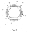
- FIG 2 is a top plan view exemplifying a motor-noise absorbing apparatus of a vacuum cleaner according to a first exemplary embodiment of the present disclosure
- FIG. 3 is a perspective view exemplifying the motor-noise absorbing apparatus according to the first exemplary embodiment of the present disclosure illustrated in FIG. 2 when it is installed in a motor housing;
- FIG. 4 is a partially cut-away top plan view exemplifying the motor-noise absorbing apparatus according to the first exemplary embodiment of the present disclosure illustrated in FIG. 2 when it is installed in the motor housing;
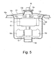
- FIG 5 is a cross-sectional view taken along line V-V in FIG. 4 ;
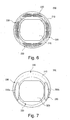
- FIGS. 6 through 8 are top plan views exemplifying motor-noise absorbing apparatuses of a vacuum cleaner according to second through fourth exemplary embodiments of the present disclosure, respectively;
- FIG 9 is a graph exemplifying results, which compares motor noises measured when the motor-noise absorbing apparatuses of the first through fourth exemplary embodiments of the present disclosure are installed, respectively, with those when not installed.
- FIG 2 is a top plan view exemplifying the motor-noise absorbing apparatus according to the first exemplary embodiment of the present disclosure
- FIG 3 is a perspective view exemplifying the motor-noise absorbing apparatus of the first exemplary embodiment illustrated in FIG. 2 when it is installed in a motor housing
- FIG 4 is a partially cut-away top plan view exemplifying the motor-noise absorbing apparatus of the first exemplary embodiment illustrated in FIG. 2 when it is installed in the motor housing
- FIG. 5 is a cross-sectional view taken along line V-V in FIG 4 .
- a motor of the vacuum cleaner on which the motor-noise absorbing apparatus 100 according to the first exemplary embodiment of the present disclosure is installed has the same construction as that of a general cleaner motor, detailed description thereof will be omitted for clarity and conciseness.
- the motor-noise absorbing apparatus 100 includes a body 110, a first air discharging part 120 and a second air discharging part 130.
- the body 110 is formed in an approximate ring shape, and as illustrated in FIGS. 3 through 5 , is seated and fixed on a peripheral part of an opening of a motor housing 10, that is, an inner circumference 10b (see FIG. 5 ) of a flange 10a, to cover a second space S2 between the motor housing 10 and the stator core 11 and thus to restrict an amount of air discharged into the second space S2.
- the body 110 is fixedly disposed, so that an outer circumference thereof is maintained compressed between the inner circumference 10b of the flange 10a and an undersurface of a housing cover 21.
- the body 110 has a portion 113 configured, so that an upper surface thereof is increasingly rounded in an inward-and-down direction toward a center side from a peripheral side.
- the portion 113 acts to smoothly discharge air from a guide vein 27 (see FIG. 1 ) into a first space S 1 between the stator core 11 and a rotor 17.
- the first air discharging part 120 is formed in the middle of the body 110, so that most of the air from the guide vein 27 is discharged into the first space S1. As illustrated in FIG 3 , the first air discharging part 120 is formed to have an area, which does not cover the stator core 11 and the first space S1.
- the second air discharging part 130 is formed to penetrate a peripheral part of the body 110, so that a portion of the air from the guide vein 27 is discharged into the second space S2.
- the second air discharging part 130 is made up of one more than, for example, four grill-shaped parts, which are formed at four positions of the body 110 approximately corresponding to the second space S2.
- the motor in which the motor-noise absorbing apparatus 100 according to the first exemplary embodiment of the present disclosure constructed as described above is mounted, guides most of discharge air, which flows from the guide vein 27 in a high speed, into the first space S 1 through the the first air discharging part 120, and discharges the rest of discharge air into the second space S2 through the second air discharging part 130. Accordingly, an amount of air discharged through the second air discharging part 130 can be restricted.
- the motor of comparison example 1 that is, the motor in which the motor-noise absorbing apparatus of the first exemplary embodiment is not installed represented primary through thirdly blade passing frequency (BPF) peak noise levels of about 85 to about 95dBA and a total overall noise level of 103.83dBA.
- BPF blade passing frequency
- the motor of comparison example 2 that is, the motor in which a motor-noise absorbing apparatus having the same construction as that of the motor-noise absorbing apparatus of the first exemplary embodiment except having no second air discharging part 130 is installed represented a total overall noise level of 101.76dBA. Since the motor-noise absorbing apparatus of example 2 included no second air discharging part 130, the motor-noise absorbing apparatus sealed the space S2 between the motor housing 10 and the stator core 11 such that all air flows in the space S 1 between the stator core 11 and the rotor 17.
- the motor having the motor-noise absorbing apparatus 100 of the first exemplary embodiment represented a total overall noise level of 102.21dBA.
- the motor in which the motor-noise absorbing apparatus having no second air discharging part 130 represented a minimum total overall noise level.
- the comparison example 2 represented as having a suction force of 77.5% to the comparison example 1, whereas the first exemplary embodiment of the present disclosure represented as having a suction force of 96.0% to the comparison example 1. Accordingly, it could be appreciated that when the noise and the suction force of the motor are considered together, the motor in which the motor-noise absorbing apparatus having the second air discharging part 130 is installed has more superior performance than the motor in which the motor-noise absorbing apparatus having no second air discharging part 130 is installed (i.e., comparison example 2).
- Motor-noise absorbing apparatuses 200, 300 and 400 of a vacuum cleaner according to second through fourth exemplary embodiments of the present disclosure illustrated in FIGS. 6 through 8 are formed in ring shapes, respectively, and include bodies 210, 310 and 410, first air discharging parts 220, 320 and 420, and second air discharging parts 230, 330 and 430, respectively.
- the motor-noise absorbing apparatuses 200, 300 and 400 of the second through fourth exemplary embodiments are configured, so that the bodies 210, 310 and 410 and the first air discharging parts 220, 320 and 420 have shapes equal to one another, respectively, but the second air discharging parts 230, 330 and 430 have shapes different from one another. That is, the second air discharging part 230 of the motor-noise absorbing apparatus 200 is formed of one more than, for example, four porous parts, each of which include a plurality of small holes is formed therein.
- the second air discharging part 330 of the motor-noise absorbing apparatus 300 is formed of two elongated holes 330a, 330b having certain areas, which are disposed at positions symmetrical to each other about the first air discharging part 320, respectively.
- the second air discharging part 430 of the motor-noise absorbing apparatus 400 is formed of four elongated holes 430a, 430b, 430c, 430d, which are disposed at positions symmetrical to each other about the first air discharging part 420, respectively.
- total overall noise levels of motors in which the motor-noise absorbing apparatuses 200, 300 and 400 of the second through fourth exemplary embodiments constructed as described above are installed represented 101.30dBA, 103.86dBA and 102.87dBA, respectively.
- suctions forces of the motors as described above represented 95.4%, 93.9% and 96.5% to the motor of comparison example 1.
- the motor-noise absorbing apparatus induces to forcibly discharge most of the discharge air flowed into the motor housing through the first space between the stator core and the rotor. Accordingly, the motor-noise absorbing apparatus according to the exemplary embodiments of the present disclosure can reduce an amount of the air discharged between the motor housing and the stator core, thereby reducing noise generating when the air collides with complicated structures disposed between the motor housing and the stator core, and thus generally reducing noise generating in the motor housing.
Landscapes
- Engineering & Computer Science (AREA)
- Mechanical Engineering (AREA)
- General Engineering & Computer Science (AREA)
- Power Engineering (AREA)
- Motor Or Generator Frames (AREA)
- Structures Of Non-Positive Displacement Pumps (AREA)
Claims (13)
- Motorgeräuschdämpfungsvorrichtung eines Staubsaugers zum Dämpfen eines Geräuschs, das in einem Motorgehäuse (10) erzeugt wird, in dem ein Motor mit einem Statorkern (11) und einem Rotor (17) angeordnet ist,
gekennzeichnet durch
einen Körper (110, 210, 310, 410), der so ausgelegt ist, dass er auf einem Umfangsteil einer Öffnung des Motorgehäuses (10) sitzt und daran befestigt ist, um eine Menge an Luft, die zwischen dem Motorgehäuse (10) und dem Statorkern (11) ausgelassen wird, einzuschränken;
einen ersten Luftauslassteil (120, 220, 320, 420), der in der Mitte des Körpers (110, 210, 310, 410) ausgebildet ist, so dass das Meiste der Luft zwischen dem Statorkern (11) und dem Rotor (17) ausgelassen wird; und
mindestens einen zweiten Luftauslassteil (130, 230, 330, 430), der so ausgebildet ist, dass er einen Umfangsteil des Körpers (110, 210, 310, 410) durchdringt, so dass ein Teil der Luft zwischen dem Motorgehäuse (10) und dem Statorkern (11) ausgelassen wird. - Vorrichtung nach Anspruch 1, wobei der zweite Luftauslassteil (130, 230, 330, 430) in einem Bereich ausgebildet ist, der kleiner ist als jener des ersten Luftauslassteils (120, 220, 320, 420), so dass die Menge der Luft, die zwischen dem Motorgehäuse (10) und dem Statorkern (11) ausgelassen wird, geringer ist als jene der Luft, die zwischen dem Statorkern (11) und dem Rotor (17) ausgelassen wird.
- Vorrichtung nach Anspruch 2, wobei der zweite Luftauslassteil (130) mindestens einen gitterförmigen Teil umfasst.
- Vorrichtung nach Anspruch 2, wobei der zweite Luftauslassteil (230) mindestens einen porösen Teil umfasst, in dem eine Vielzahl von kleinen Löchern ausgebildet ist.
- Vorrichtung nach Anspruch 2, wobei der zweite Luftauslassteil (330) mindestens zwei längliche Löcher (330a, 330b) umfasst, die zueinander symmetrisch um den ersten Luftauslassteil (320) angeordnet sind.
- Vorrichtung nach Anspruch 2, wobei der zweite Luftauslassteil (430) mindestens vier längliche Löcher (430a, 430b, 430c, 430d) umfasst, die zueinander symmetrisch um den ersten Luftauslassteil (420) angeordnet sind.
- Vorrichtung nach Anspruch 1, wobei der Körper (110, 210, 310, 410) so konfiguriert ist, dass eine obere Oberfläche davon in einer Richtung nach innen und nach unten in Richtung einer Mittelseite von einer Umfangsseite zunehmend abgerundet ist, wodurch das Meiste der Luft zwischen dem Statorkern (11) und dem Rotor (17) gleichmäßig ausgelassen wird.
- Staubsaugermotor, der aufweist:ein Motorgehäuse (10) mit einem Flansch (10a);einen Statorkern (11), der im Motorgehäuse (10) angeordnet ist;einen Rotor (17), der im Statorkern (11) angeordnet ist, so dass ein erster Raum (S1) zwischen dem Statorkern (11) und dem Rotor (17) definiert ist, wobei der Statorkern (11) im Motorgehäuse (10) so angeordnet ist, dass ein zweiter Raum (S2) zwischen dem Motorgehäuse (10) und dem Statorkern (11) definiert ist; undeine Motorgehäuseabdeckung;gekennzeichnet durcheine Motorgeräuschdämpfungsvorrichtung (100, 200, 300, 400), die zwischen dem Flansch (10a) und der Motorgehäuseabdeckung angeordnet ist, wobei die Motorgeräuschdämpfungsvorrichtung (100, 200, 300, 400) einen ersten Luftauslassteil (120, 220, 320, 420) und mindestens einen zweiten Luftauslassteil (130, 230, 330, 430) umfasst, wobei der erste (120, 220, 320, 420) und der zweite Luftauslassteil (130, 230, 330, 430) so ausgelegt sind, dass eine Menge an Luft, die durch den zweiten Raum (S2) ausgelassen wird, geringer ist als eine Menge an Luft, die durch den ersten Raum (S1) ausgelassen wird.
- Motor nach Anspruch 8, wobei der zweite Luftauslassteil (130, 230, 330, 430) in einem Bereich ausgebildet ist, der kleiner ist als jener des ersten Luftauslassteils (120, 220, 330, 430).
- Motor nach Anspruch 8, wobei der zweite Luftauslassteil (130) mindestens einen gitterförmigen Teil umfasst.
- Motor nach Anspruch 8, wobei der zweite Luftauslassteil (230) mindestens einen porösen Teil umfasst, in dem eine Vielzahl von kleinen Löchern ausgebildet ist.
- Motor nach Anspruch 8, wobei der zweite Luftauslassteil (330) mindestens zwei längliche Löcher (330a, 330b) umfasst, die zueinander symmetrisch um den ersten Luftauslassteil (320) angeordnet sind.
- Motor nach Anspruch 8, wobei der zweite Luftauslassteil (430) mindestens vier längliche Löcher (430a, 430b, 430c, 430d) umfasst, die zueinander symmetrisch um den ersten Luftauslassteil (420) angeordnet sind.
Priority Applications (1)
| Application Number | Priority Date | Filing Date | Title |
|---|---|---|---|
| SI200731469T SI1917894T1 (sl) | 2006-10-31 | 2007-06-15 | Aparat za absorpcijo hrupa motorja sesalnika za prah |
Applications Claiming Priority (1)
| Application Number | Priority Date | Filing Date | Title |
|---|---|---|---|
| KR1020060106163A KR100837362B1 (ko) | 2006-10-31 | 2006-10-31 | 진공청소기용 모터의 소음저감장치 |
Publications (2)
| Publication Number | Publication Date |
|---|---|
| EP1917894A1 EP1917894A1 (de) | 2008-05-07 |
| EP1917894B1 true EP1917894B1 (de) | 2014-03-12 |
Family
ID=38984525
Family Applications (1)
| Application Number | Title | Priority Date | Filing Date |
|---|---|---|---|
| EP07011752.8A Active EP1917894B1 (de) | 2006-10-31 | 2007-06-15 | Motorengeräuschdämpfende Vorrichtung für Staubsauger |
Country Status (5)
| Country | Link |
|---|---|
| US (1) | US8046869B2 (de) |
| EP (1) | EP1917894B1 (de) |
| KR (1) | KR100837362B1 (de) |
| RU (1) | RU2345696C1 (de) |
| SI (1) | SI1917894T1 (de) |
Families Citing this family (3)
| Publication number | Priority date | Publication date | Assignee | Title |
|---|---|---|---|---|
| KR20110004519A (ko) * | 2009-07-08 | 2011-01-14 | 삼성광주전자 주식회사 | 진공청소기의 팬모터유닛 및 진공청소기 |
| CN105634187A (zh) * | 2016-03-24 | 2016-06-01 | 苏州市润豪电机有限公司 | 无刷吸尘器电机的减震装置 |
| CN109589042B (zh) * | 2018-12-29 | 2021-01-12 | 江苏美的清洁电器股份有限公司 | 用于吸尘器的电机罩、吸尘器的电机模组及吸尘器 |
Family Cites Families (22)
| Publication number | Priority date | Publication date | Assignee | Title |
|---|---|---|---|---|
| NL78017B (de) * | 1935-06-13 | |||
| DE3443837A1 (de) * | 1984-11-30 | 1986-06-05 | Progress-Elektrogeräte Mauz & Pfeiffer GmbH & Co, 7000 Stuttgart | Staubsauger |
| US5479676A (en) * | 1994-05-12 | 1996-01-02 | Electrolux Corporation | Vacuum cleaner |
| KR970009718A (ko) * | 1995-08-31 | 1997-03-27 | 배순훈 | 진공 청소기의 배기 유로를 길게한 흡음방 |
| KR100213365B1 (ko) * | 1997-06-30 | 1999-08-02 | 전주범 | 진공청소기의 소음저감구조 |
| JPH1132947A (ja) | 1997-06-30 | 1999-02-09 | Daewoo Electron Co Ltd | 真空掃除機の吸音装置 |
| KR100233513B1 (ko) * | 1997-09-23 | 1999-12-01 | 구자홍 | 진공청소기의 공기유로구조 |
| PL323024A1 (en) | 1997-11-05 | 1999-05-10 | Zelmer | Electric vacuum cleaner |
| KR100270801B1 (ko) * | 1998-06-30 | 2000-11-01 | 전주범 | 진공청소기의 일체형 흡음장치 |
| CN1124417C (zh) * | 1999-04-20 | 2003-10-15 | 三洋电机株式会社 | 电动送风机以及使用它的电动吸尘器 |
| EP1188405A3 (de) * | 2000-09-19 | 2003-01-29 | Lg Electronics Inc. | Staubsauger mit verbesserter Kühlung |
| US6666660B2 (en) * | 2001-04-27 | 2003-12-23 | The Hoover Company | Motor-fan assembly for a floor cleaning machine |
| US6870292B2 (en) * | 2001-11-28 | 2005-03-22 | Nissan Motor Co., Ltd. | Stator for motor |
| KR100474341B1 (ko) | 2002-09-26 | 2005-03-10 | 엘지전자 주식회사 | 진공청소기용 모터의 배기 유로 구조 |
| KR100474344B1 (ko) * | 2002-10-07 | 2005-03-10 | 엘지전자 주식회사 | 진공청소기 모터의 소음 저감 장치 |
| KR100486595B1 (ko) * | 2002-11-14 | 2005-05-03 | 엘지전자 주식회사 | 진공청소기의 모터 지지 장치 |
| US7351269B2 (en) * | 2003-12-22 | 2008-04-01 | Lau Kwok Yau | Self cleaning filter and vacuum incorporating same |
| US20060213022A1 (en) * | 2004-11-05 | 2006-09-28 | Samsung Gwangju Electronics Co., Ltd. | Exhausting apparatus of motor assembly and vacuum cleaner having the same |
| KR101143773B1 (ko) * | 2004-12-03 | 2012-05-11 | 엘지전자 주식회사 | 진공청소기 팬모터의 소음감소장치 |
| KR100676317B1 (ko) * | 2005-05-18 | 2007-01-30 | 삼성광주전자 주식회사 | 진공청소기 |
| CN100423678C (zh) | 2005-11-10 | 2008-10-08 | 苏州金莱克家用电器有限公司 | 吸尘器消音装置 |
| KR100725515B1 (ko) * | 2005-12-15 | 2007-06-08 | 삼성광주전자 주식회사 | 모터 소음저감구조를 갖는 진공청소기 |
-
2006
- 2006-10-31 KR KR1020060106163A patent/KR100837362B1/ko active Active
-
2007
- 2007-04-02 US US11/732,058 patent/US8046869B2/en active Active
- 2007-04-27 RU RU2007115899/11A patent/RU2345696C1/ru not_active IP Right Cessation
- 2007-06-15 EP EP07011752.8A patent/EP1917894B1/de active Active
- 2007-06-15 SI SI200731469T patent/SI1917894T1/sl unknown
Also Published As
| Publication number | Publication date |
|---|---|
| RU2345696C1 (ru) | 2009-02-10 |
| US8046869B2 (en) | 2011-11-01 |
| EP1917894A1 (de) | 2008-05-07 |
| US20080098561A1 (en) | 2008-05-01 |
| KR100837362B1 (ko) | 2008-06-12 |
| KR20080038787A (ko) | 2008-05-07 |
| SI1917894T1 (sl) | 2014-07-31 |
| RU2007115899A (ru) | 2008-11-10 |
Similar Documents
| Publication | Publication Date | Title |
|---|---|---|
| EP1929914B1 (de) | Gehäuseanordnung für einen Lüftermotor zur Geräuschminderung | |
| CN1040720C (zh) | 真空吸尘器 | |
| RU2286077C2 (ru) | Узел всасывающей щетки (варианты) и пылесос с такой щеткой | |
| KR102330551B1 (ko) | 진공 흡입 유닛 | |
| EP1400699B1 (de) | Elektrisches Gebläse und damit ausgerüsteter Staubsauger | |
| KR100233513B1 (ko) | 진공청소기의 공기유로구조 | |
| KR20010014670A (ko) | 전동송풍기 및 그것을 사용한 전기청소기 | |
| EP0888742A1 (de) | Geräuschdämpfungssystem für Staubsauger | |
| EP1917894A1 (de) | Motorengeräuschdämpfende Vorrichtung für Staubsauger | |
| JP4951588B2 (ja) | 電動送風機及びこれを備えた電気掃除機 | |
| US20130133156A1 (en) | Electric blower and electric cleaner with same | |
| US20060213022A1 (en) | Exhausting apparatus of motor assembly and vacuum cleaner having the same | |
| JP2005226608A (ja) | 電動送風機及びそれを用いた電気掃除機 | |
| JP3018545B2 (ja) | 電動送風機 | |
| KR100474344B1 (ko) | 진공청소기 모터의 소음 저감 장치 | |
| JP2001003898A (ja) | 電動送風機及びそれを用いた電気掃除機 | |
| JP3804221B2 (ja) | 電動送風機 | |
| KR0133743B1 (ko) | 후방차음덮개를 가지는 진공청소기의 흡음방 | |
| JP2007146746A (ja) | 電動送風機及びそれを用いた電気掃除機 | |
| JP2006342690A (ja) | 電動送風機及び電気掃除機 | |
| KR970007007Y1 (ko) | 청소기 모터의 흡음구조 | |
| JP3252878U (ja) | 低騒音の掃除機 | |
| JPS60113097A (ja) | 電動送風機 | |
| KR100546588B1 (ko) | 진공청소기의 전동기 지지구조체 | |
| JP4419253B2 (ja) | 電気掃除機 |
Legal Events
| Date | Code | Title | Description |
|---|---|---|---|
| PUAI | Public reference made under article 153(3) epc to a published international application that has entered the european phase |
Free format text: ORIGINAL CODE: 0009012 |
|
| AK | Designated contracting states |
Kind code of ref document: A1 Designated state(s): AT BE BG CH CY CZ DE DK EE ES FI FR GB GR HU IE IS IT LI LT LU LV MC MT NL PL PT RO SE SI SK TR |
|
| AX | Request for extension of the european patent |
Extension state: AL BA HR MK RS |
|
| 17P | Request for examination filed |
Effective date: 20080711 |
|
| AKX | Designation fees paid |
Designated state(s): DE IT SI |
|
| RAP1 | Party data changed (applicant data changed or rights of an application transferred) |
Owner name: SAMSUNG ELECTRONICS CO., LTD. |
|
| RAP1 | Party data changed (applicant data changed or rights of an application transferred) |
Owner name: SAMSUNG ELECTRONICS CO., LTD. |
|
| GRAP | Despatch of communication of intention to grant a patent |
Free format text: ORIGINAL CODE: EPIDOSNIGR1 |
|
| INTG | Intention to grant announced |
Effective date: 20131010 |
|
| GRAS | Grant fee paid |
Free format text: ORIGINAL CODE: EPIDOSNIGR3 |
|
| GRAA | (expected) grant |
Free format text: ORIGINAL CODE: 0009210 |
|
| AK | Designated contracting states |
Kind code of ref document: B1 Designated state(s): DE IT SI |
|
| REG | Reference to a national code |
Ref country code: DE Ref legal event code: R096 Ref document number: 602007035472 Country of ref document: DE Effective date: 20140424 |
|
| REG | Reference to a national code |
Ref country code: DE Ref legal event code: R097 Ref document number: 602007035472 Country of ref document: DE |
|
| PLBE | No opposition filed within time limit |
Free format text: ORIGINAL CODE: 0009261 |
|
| STAA | Information on the status of an ep patent application or granted ep patent |
Free format text: STATUS: NO OPPOSITION FILED WITHIN TIME LIMIT |
|
| 26N | No opposition filed |
Effective date: 20141215 |
|
| REG | Reference to a national code |
Ref country code: DE Ref legal event code: R097 Ref document number: 602007035472 Country of ref document: DE Effective date: 20141215 |
|
| PGFP | Annual fee paid to national office [announced via postgrant information from national office to epo] |
Ref country code: IT Payment date: 20210610 Year of fee payment: 15 |
|
| PGFP | Annual fee paid to national office [announced via postgrant information from national office to epo] |
Ref country code: SI Payment date: 20210525 Year of fee payment: 15 |
|
| REG | Reference to a national code |
Ref country code: SI Ref legal event code: KO00 Effective date: 20230214 |
|
| PG25 | Lapsed in a contracting state [announced via postgrant information from national office to epo] |
Ref country code: SI Free format text: LAPSE BECAUSE OF NON-PAYMENT OF DUE FEES Effective date: 20220616 |
|
| PG25 | Lapsed in a contracting state [announced via postgrant information from national office to epo] |
Ref country code: IT Free format text: LAPSE BECAUSE OF NON-PAYMENT OF DUE FEES Effective date: 20220615 |
|
| PGFP | Annual fee paid to national office [announced via postgrant information from national office to epo] |
Ref country code: DE Payment date: 20250520 Year of fee payment: 19 |