EP1917164B1 - Airbaggehäuse - Google Patents
Airbaggehäuse Download PDFInfo
- Publication number
- EP1917164B1 EP1917164B1 EP06829903A EP06829903A EP1917164B1 EP 1917164 B1 EP1917164 B1 EP 1917164B1 EP 06829903 A EP06829903 A EP 06829903A EP 06829903 A EP06829903 A EP 06829903A EP 1917164 B1 EP1917164 B1 EP 1917164B1
- Authority
- EP
- European Patent Office
- Prior art keywords
- airbag housing
- airbag
- walls
- stiffening
- longitudinal
- Prior art date
- Legal status (The legal status is an assumption and is not a legal conclusion. Google has not performed a legal analysis and makes no representation as to the accuracy of the status listed.)
- Not-in-force
Links
- 239000003351 stiffener Substances 0.000 description 9
- 239000000463 material Substances 0.000 description 5
Images
Classifications
-
- B—PERFORMING OPERATIONS; TRANSPORTING
- B60—VEHICLES IN GENERAL
- B60R—VEHICLES, VEHICLE FITTINGS, OR VEHICLE PARTS, NOT OTHERWISE PROVIDED FOR
- B60R21/00—Arrangements or fittings on vehicles for protecting or preventing injuries to occupants or pedestrians in case of accidents or other traffic risks
- B60R21/02—Occupant safety arrangements or fittings, e.g. crash pads
- B60R21/16—Inflatable occupant restraints or confinements designed to inflate upon impact or impending impact, e.g. air bags
- B60R21/20—Arrangements for storing inflatable members in their non-use or deflated condition; Arrangement or mounting of air bag modules or components
- B60R21/217—Inflation fluid source retainers, e.g. reaction canisters; Connection of bags, covers, diffusers or inflation fluid sources therewith or together
-
- B—PERFORMING OPERATIONS; TRANSPORTING
- B60—VEHICLES IN GENERAL
- B60R—VEHICLES, VEHICLE FITTINGS, OR VEHICLE PARTS, NOT OTHERWISE PROVIDED FOR
- B60R21/00—Arrangements or fittings on vehicles for protecting or preventing injuries to occupants or pedestrians in case of accidents or other traffic risks
- B60R21/02—Occupant safety arrangements or fittings, e.g. crash pads
- B60R21/16—Inflatable occupant restraints or confinements designed to inflate upon impact or impending impact, e.g. air bags
- B60R21/20—Arrangements for storing inflatable members in their non-use or deflated condition; Arrangement or mounting of air bag modules or components
-
- B—PERFORMING OPERATIONS; TRANSPORTING
- B60—VEHICLES IN GENERAL
- B60R—VEHICLES, VEHICLE FITTINGS, OR VEHICLE PARTS, NOT OTHERWISE PROVIDED FOR
- B60R21/00—Arrangements or fittings on vehicles for protecting or preventing injuries to occupants or pedestrians in case of accidents or other traffic risks
- B60R21/02—Occupant safety arrangements or fittings, e.g. crash pads
- B60R21/16—Inflatable occupant restraints or confinements designed to inflate upon impact or impending impact, e.g. air bags
- B60R21/20—Arrangements for storing inflatable members in their non-use or deflated condition; Arrangement or mounting of air bag modules or components
- B60R21/205—Arrangements for storing inflatable members in their non-use or deflated condition; Arrangement or mounting of air bag modules or components in dashboards
Definitions
- Airbag housings are exposed to high pressure loads at the time of deployment of the airbag. This leads in particular to housings of passenger airbags, which usually have high side walls, to deformations. Housing of passenger airbag modules are seen in plan view rectangular shape to fully utilize the mostly rectangular space in the instrument panel. In order to minimize the deformation of the airbag housing stiffeners are provided on these housings. However, the stiffeners reduce the space required for the airbag folding space, since the airbag housing must be necessarily reduced to fit including the stiffeners in the given space of the instrument panel. In general, a plurality of stiffening ribs is provided on the outside of the airbag housing in order to achieve the necessary rigidity of the housing walls. This leads to increased material consumption and increased weight of the airbag housing. To further optimize the strength of the corners of the airbag housing are more or less rounded. So is out of the US Pat. No. 6,203,056 B1 an airbag housing with strongly rounded corners known.
- the invention has for its object to realize an airbag housing with a similar Faltraumvolumen as a stiffened airbag housing of the prior art with less material.
- the side walls In an airbag housing, in particular for passenger airbag modules with high side walls, the side walls, seen in plan view, are curved, with two inwardly curved longitudinal walls and two outwardly curved end walls are arranged. Although these curved walls limit the Faltraumvolumen in similar size as the stiffened side walls of the airbag housing of the prior art, but require less or no stiffeners, so that material, cost and weight can be saved.
- These side walls are preferably formed as circular sections.
- the side walls are curved at least in sections alternately inwards and outwards.
- stiffeners may be provided on the longitudinal walls outside.
- a stiffening part extending in the longitudinal direction of the airbag housing is provided as stiffening on each longitudinal wall. Between this and the longitudinal wall at least one stiffening rib is provided. But this stiffening requires much less stiffening ribs than a housing of the prior art.
- a stiffening rib is provided in the middle of each longitudinal wall.
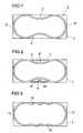
- the figures show the rectangular space 1, which is available in the instrument panel for the airbag housing of the front passenger airbag available.
- an airbag housing 2 is shown, whose walls represent circular sections.
- the airbag housing 2 has two longitudinal walls 3, 4, which represent circular segments and are curved inwards. These are connected to end walls 5, 6, which are semicircular and arched outwards. With a corresponding wall thickness with less material than with an airbag housing of the prior art, this shape ensures that the airbag housing deforms only to a slight extent.
- the Fig. 2 shows a variant of the embodiment according to Fig. 1 ,
- the airbag housing seen in plan view has the same shape as the airbag housing 2 of Fig. 1 ,
- stiffeners 7, 8 are arranged in the region of the longitudinal walls 3, 4.
- a stiffening rib 9 and 10 is provided in the middle of the longitudinal wall. This stiffening requires significantly less material than a stiffener in a prior art airbag housing.
- end walls 11, 12 as in the Figures 1 and 2 formed as outwardly curved semicircles.
- longitudinal walls 13, 14 are provided in this embodiment, which are alternately curved inwards and outwards.
- the invention is not limited to the illustrated embodiments. Rather, other embodiments are possible in which the side walls seen in plan view are curved.
Landscapes
- Engineering & Computer Science (AREA)
- Mechanical Engineering (AREA)
- Air Bags (AREA)
Abstract
Description
- Airbaggehäuse sind zum Zeitpunkt der Auslösung des Airbags hohen Druckbelastungen ausgesetzt. Das führt insbesondere bei Gehäusen von Beifahrerairbags, die gewöhnlich hohe Seitenwände aufweisen, zu Deformationen. Gehäuse von Beifahrerairbagmodulen sind in der Draufsicht gesehen rechteckförmig um den zumeist rechteckförmigen Bauraum in der Armaturentafel vollständig auszunutzen. Um die Deformationen des Airbaggehäuses zu minimieren sind an diesen Gehäusen Versteifungen vorgesehen. Die Versteifungen verkleinern aber den für den Gassack benötigten Faltraum, da das Airbaggehäuse zwangsläufig verkleinert werden muss, um einschließlich der Versteifungen in den vorgegebenen Bauraum der Instrumententafel zu passen. In der Regel ist eine Vielzahl von Versteifungsrippen außen am Airbaggehäuse vorgesehen, um die notwendige Steifigkeit der Gehäusewände zu erreichen. Das führt zu erhöhtem Materialverbrauch und zu erhöhtem Gewicht des Airbaggehäuses. Zur weiteren Optimierung der Festigkeit sind die Ecken des Airbaggehäuses mehr oder weniger stark abgerundet. So ist aus der
US 6 203 056 B1 ein Airbaggehäuse mit stark abgerundeten Ecken bekannt. - Der Erfindung liegt die Aufgabe zugrunde, ein Airbaggehäuse mit einem ähnlichen Faltraumvolumen wie ein versteiftes Airbaggehäuse des Standes der Technik mit geringerem Materialaufwand zu realisieren.
- Erfindungsgemäß wird das gemäß den Merkmalen des Anspruchs 1 erreicht.
- Bei einem Airbaggehäuse, insbesondere für Beifahrerairbagmodule mit hohen Seitenwänden, verlaufen die Seitenwände, in der Draufsicht gesehen, kurvenförmig, wobei zwei nach innen gewölbte Längswände und zwei nach außen gewölbte Stirnwände angeordnet sind. Diese kurvenförmigen Wände schränken zwar das Faltraumvolumen in ähnlicher Größe wie die versteiften Seitenwände der Airbaggehäuse des Standes der Technik ein, benötigen aber weniger oder keine Versteifungen, so dass Material, Kosten und Gewicht eingespart werden.
- Diese Seitenwände sind vorzugsweise als Kreisabschnitte ausgebildet.
- Bei einer weiteren Ausführungsform sind die Seitenwände in sich zumindest abschnittsweise abwechselnd nach innen und außen gewölbt.
- Zur Erhöhung der Festigkeit können an den Längswänden außen Versteifungen vorgesehen sein. Vorzugsweise ist als Versteifung an jeder Längswand ein in Längsrichtung des Airbaggehäuses verlaufendes Versteifungsteil vorgesehen. Zwischen diesem und der Längswand ist mindestens eine Versteifungsrippe vorgesehen. Diese Versteifung benötigt aber wesentlich weniger Versteifungsrippen als ein Gehäuse des Standes der Technik. Vorzugsweise ist eine Versteifungsrippe in der Mitte jeder Längswand vorgesehen.
- Die Erfindung soll in Ausführungsbeispielen anhand von Zeichnungen erläutert werden. Es zeigen:
- Fig. 1
- die Draufsicht auf eine erste Ausführungsform des erfindungsgemäßen Airbaggehäuses für einen Beifahrerairbag;
- Fig. 2
- das Airbaggehäuse nach
Fig. 1 mit Versteifungen; - Fig. 3
- die Draufsicht auf eine zweite Ausführungsform des erfindungsgemäßen Airbaggehäuses für einen Beifahrerairbag.
- Die Figuren zeigen den rechteckförmigen Bauraum 1, der in der Instrumententafel für das Airbaggehäuse des Beifahrerairbags zur Verfügung steht. In der
Fig. 1 ist ein Airbaggehäuse 2 dargestellt, dessen Wände Kreisabschnitte darstellen. Das Airbaggehäuse 2 weist zwei Längswände 3, 4 auf, die Kreissegmente darstellen und nach innen gewölbt sind. Diese sind mit Stirnwänden 5, 6 verbunden, die halbkreisförmig ausgestaltet und nach außen gewölbt sind. Diese Form gewährleistet bei einer entsprechenden Wandstärke mit weniger Material als bei einem Airbaggehäuse des Standes der Technik, dass sich das Airbaggehäuse nur in geringem Maße deformiert. - Die
Fig. 2 zeigt eine Variante der Ausführungsform nachFig. 1 . Bei dieser Variante weist das Airbaggehäuse in der Draufsicht gesehen die gleiche Form auf wie das Airbaggehäuse 2 derFig. 1 . Gegenüber diesem sind im Bereich der Längswände 3, 4 Versteifungen 7, 8 angeordnet. Zwischen jeder Längswand 3, 4 und der zugeordneten Versteifung 7, 8 ist in der Mitte der Längswand eine Versteifungsrippe 9 bzw. 10 vorgesehen. Diese Versteifung erfordert wesentlich weniger Material als eine Versteifung bei einem Airbaggehäuse des Standes der Technik. - Bei der Ausführungsform der
Fig. 3 sind Stirnwände 11, 12 wie in denFiguren 1 und 2 als nach außen gewölbte Halbkreise ausgebildet. Im Unterschied zu denFiguren 1 und 2 sind bei dieser Ausführungsform Längswände 13, 14 vorgesehen, die abwechselnd nach innen und nach außen gewölbt sind. - Die Erfindung ist nicht auf die dargestellten Ausführungsformen beschränkt. Vielmehr sind weitere Ausführungsformen möglich, bei denen die Seitenwände in der Draufsicht gesehen kurvenförmig verlaufen.
Claims (6)
- Airbaggehäuse, insbesondere für Beifahrerairbagmodule mit hohen Seitenwänden,
dadurch gekennzeichnet, dass die Seitenwände (3, 4, 5, 6), in der Draufsicht gesehen, kurvenförmig verlaufen, wobei zwei nach innen gewölbte Längswände (3, 4) und zwei nach außen gewölbte Stirnwände (5, 6) angeordnet sind. - Airbaggehäuse nach Anspruch 1, dadurch gekennzeichnet, dass die Seitenwände (3, 4, 5, 6) als Kreisabschnitte ausgebildet sind.
- Airbaggehäuse nach Anspruch 1, dadurch gekennzeichnet, dass die Seitenwände (13, 14) in sich zumindest abschnittsweise abwechselnd nach innen und außen gewölbt sind.
- Airbaggehäuse nach mindestens einem der vorhergehenden Ansprüche, dadurch gekennzeichnet, dass die Längswände (3, 4) außen Versteifungen (7, 8, 9, 10) aufweisen.
- Airbaggehäuse nach Anspruch 4, dadurch gekennzeichnet, dass als Versteifung an jeder Längswand (3, 4) ein in Längsrichtung des Airbaggehäuses (2) verlaufendes Versteifungsteil (7, 8) vorgesehen ist, zwischen dem und der Längswand (3, 4) mindestens eine Versteifungsrippe (9, 10) angeordnet ist.
- Airbaggehäuse nach Anspruch 5, dadurch gekennzeichnet, dass eine einzige Versteifungsrippe (9, 10) in der Mitte jeder Längswand (3, 4) angeordnet ist.
Applications Claiming Priority (2)
| Application Number | Priority Date | Filing Date | Title |
|---|---|---|---|
| DE202006000300U DE202006000300U1 (de) | 2006-01-05 | 2006-01-05 | Airbaggehäuse |
| PCT/EP2006/012636 WO2007077030A1 (de) | 2006-01-05 | 2006-12-20 | Airbaggehäuse |
Publications (2)
| Publication Number | Publication Date |
|---|---|
| EP1917164A1 EP1917164A1 (de) | 2008-05-07 |
| EP1917164B1 true EP1917164B1 (de) | 2009-04-01 |
Family
ID=36580628
Family Applications (1)
| Application Number | Title | Priority Date | Filing Date |
|---|---|---|---|
| EP06829903A Not-in-force EP1917164B1 (de) | 2006-01-05 | 2006-12-20 | Airbaggehäuse |
Country Status (6)
| Country | Link |
|---|---|
| US (1) | US20090001700A1 (de) |
| EP (1) | EP1917164B1 (de) |
| JP (1) | JP4898833B2 (de) |
| CN (1) | CN101316743B (de) |
| DE (2) | DE202006000300U1 (de) |
| WO (1) | WO2007077030A1 (de) |
Families Citing this family (4)
| Publication number | Priority date | Publication date | Assignee | Title |
|---|---|---|---|---|
| DE102009030753B4 (de) * | 2009-06-27 | 2017-08-03 | GM Global Technology Operations LLC (n. d. Ges. d. Staates Delaware) | Airbagmodul mit einem Airbaggehäuse und Kraftfahrzeuginneneinrichtung mit einem solchen Airbagmodul |
| US8641082B2 (en) * | 2012-07-09 | 2014-02-04 | Toyoda Gosei Co. Ltd. | Airbag module case |
| DE102013005672B4 (de) * | 2013-04-03 | 2015-09-24 | Autoliv Development Ab | Airbaggehäuse |
| US11285900B1 (en) * | 2020-10-22 | 2022-03-29 | Ford Global Technologies, Llc | Airbag housing |
Family Cites Families (14)
| Publication number | Priority date | Publication date | Assignee | Title |
|---|---|---|---|---|
| DE2035742A1 (de) * | 1970-07-18 | 1972-01-27 | Daimler-Benz Ag, 7000 Stuttgart | Kraftwagen mit Prallsäcken zum Schutz der Fahrzeuginsassen |
| DE8619670U1 (de) * | 1986-07-22 | 1987-08-06 | Trw Repa Gmbh, 73553 Alfdorf | Gaskissen-Aufprallschutzvorrichtung für Kraftfahrzeuge |
| KR0155087B1 (ko) * | 1995-06-30 | 1998-10-15 | 배순훈 | 장착이 용이한 차량용 에어백 |
| US5553887A (en) * | 1995-09-29 | 1996-09-10 | Takata Inc. | Inflatable restraint modular housing with deployment directing feature |
| JPH09277897A (ja) * | 1996-04-15 | 1997-10-28 | Toyo Tire & Rubber Co Ltd | エアバッグ装置 |
| DE19703787B4 (de) * | 1997-02-01 | 2005-11-24 | ZF Lemförder Metallwaren AG | Gehäuse für den Gassack in einem Kraftfahrzeug |
| DE19703767B4 (de) * | 1997-02-01 | 2005-06-30 | ZF Lemförder Metallwaren AG | Gehäuse für den Gassack in einem Kraftfahrzeug |
| GB2323339B (en) * | 1997-03-21 | 2001-07-11 | Alliedsignal Deutschland Gmbh | Airbag housing and cover |
| US6203056B1 (en) | 1997-06-09 | 2001-03-20 | Textron Automotive Company Inc. | Apparatus for deploying an airbag through a hard panel |
| DE29715738U1 (de) * | 1997-09-02 | 1998-01-08 | Trw Occupant Restraint Systems Gmbh, 73551 Alfdorf | Einrichten zum Befestigen eines Gassacks in einem Gassack-Modul |
| DE29814233U1 (de) * | 1998-08-07 | 1998-10-22 | Delphi Automotive Systems Deutschland GmbH, 42369 Wuppertal | Luftsackmodul |
| US6422589B1 (en) * | 1998-12-18 | 2002-07-23 | Delphi Technologies, Inc. | Recyclable airbag module housing |
| US6435554B1 (en) * | 2000-11-21 | 2002-08-20 | Trw Vehicle Safety Systems Inc. | Knee bolster apparatus with center tether |
| DE10216349C1 (de) * | 2002-04-13 | 2003-11-27 | Autoliv Dev | Gehäuse für eine Airbageinrichtung mit Gehäuseversteifungen |
-
2006
- 2006-01-05 DE DE202006000300U patent/DE202006000300U1/de not_active Expired - Lifetime
- 2006-12-20 EP EP06829903A patent/EP1917164B1/de not_active Not-in-force
- 2006-12-20 WO PCT/EP2006/012636 patent/WO2007077030A1/de not_active Ceased
- 2006-12-20 JP JP2008548952A patent/JP4898833B2/ja not_active Expired - Fee Related
- 2006-12-20 DE DE502006003340T patent/DE502006003340D1/de active Active
- 2006-12-20 CN CN2006800427316A patent/CN101316743B/zh not_active Expired - Fee Related
-
2008
- 2008-07-03 US US12/216,468 patent/US20090001700A1/en not_active Abandoned
Also Published As
| Publication number | Publication date |
|---|---|
| JP2009522163A (ja) | 2009-06-11 |
| CN101316743A (zh) | 2008-12-03 |
| CN101316743B (zh) | 2011-01-26 |
| EP1917164A1 (de) | 2008-05-07 |
| JP4898833B2 (ja) | 2012-03-21 |
| DE502006003340D1 (de) | 2009-05-14 |
| DE202006000300U1 (de) | 2006-05-24 |
| WO2007077030A1 (de) | 2007-07-12 |
| US20090001700A1 (en) | 2009-01-01 |
Similar Documents
| Publication | Publication Date | Title |
|---|---|---|
| DE102016120850B4 (de) | Batteriegehäuse | |
| EP3616247B1 (de) | Akkumulatoranordnung | |
| DE102015114807A1 (de) | Nahtlose Instrumententafelbeifahrerairbagklappe | |
| EP2459432B1 (de) | Baukastensystem und verfahren zum herstellen eines dachmoduls | |
| WO2018153880A1 (de) | Batteriegehäuse für eine fahrzeugbatterie und fahrgestell für ein elektrofahrzeug | |
| DE102020122075A1 (de) | Untere Fahrzeugstruktur | |
| DE102011087438A1 (de) | Vorhangairbaganordnung für ein Kraftfahrzeug | |
| DE102017123865B4 (de) | Vorrichtung zur Aufnahme einer Mehrzahl von Akkumulatoren für den Betrieb eines einen Elektroantrieb aufweisenden Kraftfahrzeuges | |
| DE102014013582A1 (de) | Dachstruktur für ein Fahrzeugdach, insbesondere eines Personenkraftwagens, sowie Baukastensystem für Bauvarianten einer solchen Dachstruktur | |
| WO2007077030A1 (de) | Airbaggehäuse | |
| EP1902181B1 (de) | Schachtoberteil | |
| EP3426021A1 (de) | Wandelement für einen tierkäfig | |
| EP2786922A1 (de) | Kunststoffkarosserie eines Kraftfahrzeugs aus Kunststoffelementen und entsprechende Verbindungen der Elemente | |
| DE102007031091A1 (de) | Vorrichtung zum Herstellen eines Fahrzeugreifens mit einer Karkasstrommel | |
| EP3329753B1 (de) | Elektrische schaltungsanordnung mit kondensator mit gehäusefunktion | |
| DE102022117700B4 (de) | Elektrofahrzeug mit verstärktem Schweller | |
| EP2433478B1 (de) | Gehäuse oder gehäuseteil für ein steuergerät eines kraftfahrzeugs | |
| EP4074573B1 (de) | Balg für eine übergangseinrichtung | |
| EP1888379B1 (de) | Abdeckkappe für ein airbagmodul | |
| EP3741592B1 (de) | Balgelement | |
| DE202016101366U1 (de) | Verstärkungsleiste und Vorrichtung mit Verstärkungsleiste | |
| DE102004012253A1 (de) | Gehäuse aus biegbarem Material | |
| DE102015208670B4 (de) | Dachrahmen | |
| DE202012003531U1 (de) | Dachplane | |
| DE102010053311A1 (de) | Gurtband für einen Sicherheitsgurt eines Fahrzeugs |
Legal Events
| Date | Code | Title | Description |
|---|---|---|---|
| PUAI | Public reference made under article 153(3) epc to a published international application that has entered the european phase |
Free format text: ORIGINAL CODE: 0009012 |
|
| 17P | Request for examination filed |
Effective date: 20080317 |
|
| AK | Designated contracting states |
Kind code of ref document: A1 Designated state(s): DE FR |
|
| GRAP | Despatch of communication of intention to grant a patent |
Free format text: ORIGINAL CODE: EPIDOSNIGR1 |
|
| RBV | Designated contracting states (corrected) |
Designated state(s): DE FR |
|
| GRAS | Grant fee paid |
Free format text: ORIGINAL CODE: EPIDOSNIGR3 |
|
| GRAA | (expected) grant |
Free format text: ORIGINAL CODE: 0009210 |
|
| AK | Designated contracting states |
Kind code of ref document: B1 Designated state(s): DE FR |
|
| REF | Corresponds to: |
Ref document number: 502006003340 Country of ref document: DE Date of ref document: 20090514 Kind code of ref document: P |
|
| PLBE | No opposition filed within time limit |
Free format text: ORIGINAL CODE: 0009261 |
|
| STAA | Information on the status of an ep patent application or granted ep patent |
Free format text: STATUS: NO OPPOSITION FILED WITHIN TIME LIMIT |
|
| 26N | No opposition filed |
Effective date: 20100105 |
|
| PGFP | Annual fee paid to national office [announced via postgrant information from national office to epo] |
Ref country code: FR Payment date: 20111219 Year of fee payment: 6 |
|
| REG | Reference to a national code |
Ref country code: DE Ref legal event code: R082 Ref document number: 502006003340 Country of ref document: DE Representative=s name: MAIKOWSKI & NINNEMANN PATENTANWAELTE, DE |
|
| REG | Reference to a national code |
Ref country code: DE Ref legal event code: R082 Ref document number: 502006003340 Country of ref document: DE Representative=s name: MAIKOWSKI & NINNEMANN PATENTANWAELTE, DE Effective date: 20120904 Ref country code: DE Ref legal event code: R081 Ref document number: 502006003340 Country of ref document: DE Owner name: TAKATA AKTIENGESELLSCHAFT, DE Free format text: FORMER OWNER: TAKATA-PETRI AG, 63743 ASCHAFFENBURG, DE Effective date: 20120904 Ref country code: DE Ref legal event code: R082 Ref document number: 502006003340 Country of ref document: DE Representative=s name: MAIKOWSKI & NINNEMANN PATENTANWAELTE PARTNERSC, DE Effective date: 20120904 |
|
| REG | Reference to a national code |
Ref country code: FR Ref legal event code: ST Effective date: 20130830 |
|
| PG25 | Lapsed in a contracting state [announced via postgrant information from national office to epo] |
Ref country code: FR Free format text: LAPSE BECAUSE OF NON-PAYMENT OF DUE FEES Effective date: 20130102 |
|
| PGFP | Annual fee paid to national office [announced via postgrant information from national office to epo] |
Ref country code: DE Payment date: 20180228 Year of fee payment: 12 |
|
| REG | Reference to a national code |
Ref country code: DE Ref legal event code: R119 Ref document number: 502006003340 Country of ref document: DE |
|
| PG25 | Lapsed in a contracting state [announced via postgrant information from national office to epo] |
Ref country code: DE Free format text: LAPSE BECAUSE OF NON-PAYMENT OF DUE FEES Effective date: 20190702 |