EP1916152B2 - Vorderstruktur eines Kraftfahrzeugs und damit ausgestattetes Kraftfahrzeug - Google Patents
Vorderstruktur eines Kraftfahrzeugs und damit ausgestattetes Kraftfahrzeug Download PDFInfo
- Publication number
- EP1916152B2 EP1916152B2 EP07291263.7A EP07291263A EP1916152B2 EP 1916152 B2 EP1916152 B2 EP 1916152B2 EP 07291263 A EP07291263 A EP 07291263A EP 1916152 B2 EP1916152 B2 EP 1916152B2
- Authority
- EP
- European Patent Office
- Prior art keywords
- fixed
- arm
- transverse
- bumper
- body shell
- Prior art date
- Legal status (The legal status is an assumption and is not a legal conclusion. Google has not performed a legal analysis and makes no representation as to the accuracy of the status listed.)
- Ceased
Links
- 239000006096 absorbing agent Substances 0.000 claims description 6
- 230000035939 shock Effects 0.000 claims description 3
- 230000003287 optical effect Effects 0.000 description 31
- 230000000295 complement effect Effects 0.000 description 1
- 239000011521 glass Substances 0.000 description 1
- 238000002955 isolation Methods 0.000 description 1
- 238000004519 manufacturing process Methods 0.000 description 1
- 238000000034 method Methods 0.000 description 1
- 230000002093 peripheral effect Effects 0.000 description 1
- 238000011084 recovery Methods 0.000 description 1
Images
Classifications
-
- B—PERFORMING OPERATIONS; TRANSPORTING
- B62—LAND VEHICLES FOR TRAVELLING OTHERWISE THAN ON RAILS
- B62D—MOTOR VEHICLES; TRAILERS
- B62D25/00—Superstructure or monocoque structure sub-units; Parts or details thereof not otherwise provided for
- B62D25/08—Front or rear portions
- B62D25/082—Engine compartments
- B62D25/084—Radiator supports
-
- B—PERFORMING OPERATIONS; TRANSPORTING
- B60—VEHICLES IN GENERAL
- B60Q—ARRANGEMENT OF SIGNALLING OR LIGHTING DEVICES, THE MOUNTING OR SUPPORTING THEREOF OR CIRCUITS THEREFOR, FOR VEHICLES IN GENERAL
- B60Q1/00—Arrangement of optical signalling or lighting devices, the mounting or supporting thereof or circuits therefor
- B60Q1/02—Arrangement of optical signalling or lighting devices, the mounting or supporting thereof or circuits therefor the devices being primarily intended to illuminate the way ahead or to illuminate other areas of way or environments
- B60Q1/04—Arrangement of optical signalling or lighting devices, the mounting or supporting thereof or circuits therefor the devices being primarily intended to illuminate the way ahead or to illuminate other areas of way or environments the devices being headlights
- B60Q1/0408—Arrangement of optical signalling or lighting devices, the mounting or supporting thereof or circuits therefor the devices being primarily intended to illuminate the way ahead or to illuminate other areas of way or environments the devices being headlights built into the vehicle body, e.g. details concerning the mounting of the headlamps on the vehicle body
- B60Q1/0441—Arrangement of optical signalling or lighting devices, the mounting or supporting thereof or circuits therefor the devices being primarily intended to illuminate the way ahead or to illuminate other areas of way or environments the devices being headlights built into the vehicle body, e.g. details concerning the mounting of the headlamps on the vehicle body the housing being fastened onto the vehicle body using means other than screws
-
- B—PERFORMING OPERATIONS; TRANSPORTING
- B60—VEHICLES IN GENERAL
- B60Q—ARRANGEMENT OF SIGNALLING OR LIGHTING DEVICES, THE MOUNTING OR SUPPORTING THEREOF OR CIRCUITS THEREFOR, FOR VEHICLES IN GENERAL
- B60Q1/00—Arrangement of optical signalling or lighting devices, the mounting or supporting thereof or circuits therefor
- B60Q1/02—Arrangement of optical signalling or lighting devices, the mounting or supporting thereof or circuits therefor the devices being primarily intended to illuminate the way ahead or to illuminate other areas of way or environments
- B60Q1/04—Arrangement of optical signalling or lighting devices, the mounting or supporting thereof or circuits therefor the devices being primarily intended to illuminate the way ahead or to illuminate other areas of way or environments the devices being headlights
- B60Q1/0408—Arrangement of optical signalling or lighting devices, the mounting or supporting thereof or circuits therefor the devices being primarily intended to illuminate the way ahead or to illuminate other areas of way or environments the devices being headlights built into the vehicle body, e.g. details concerning the mounting of the headlamps on the vehicle body
- B60Q1/045—Arrangement of optical signalling or lighting devices, the mounting or supporting thereof or circuits therefor the devices being primarily intended to illuminate the way ahead or to illuminate other areas of way or environments the devices being headlights built into the vehicle body, e.g. details concerning the mounting of the headlamps on the vehicle body with provision for adjusting the alignment of the headlamp housing with respect to the vehicle body
Definitions
- the present invention relates to a front unit of a motor vehicle, according to the preamble of claim 1.
- WO 2007/140892 is part of the state of the art only under Article 54 (3) EPC 2000. It describes a vehicle front structure in which a structural member carrying a radiator is placed in front of the front side member plates.
- JP 03-284481 and WO 2004/085230 describe motor vehicle front units which include a rigid fixing of the optical units on the body of the motor vehicle.
- EP 1 702 834 according to the preamble and EP 1,623,873 describe flexible optical unit support arms fixed to the body of the motor vehicle.
- the front units of motor vehicles generally include a front face which has a central part and two side parts, a bumper, and a bumper skin forming a fairing of this bumper.
- the front units further comprise two arms each extending from the central part towards a respective lateral part, and forming members for supporting said bumper skin, and two optical units.
- Each optical unit is supported by a respective lateral part and has a lateral peripheral part adapted to cooperate with a complementary recess of a respective front wing part.
- a major difficulty encountered by automobile manufacturers consists in accurately positioning the optical units with respect to the appearance elements constituted by the fenders and the bumper skin. This adjustment is important because a lack of surface continuity of the visible part of the optical unit, that is to say of the glass, of the corresponding wing, and of the bumper skin significantly degrades the aesthetic quality. of the vehicle.
- precise adjustment of the position of the optical unit with respect to the fender and the bumper skin is difficult to maintain between the operation of mounting the optical units on the front face and the assembly operation. of the front unit fitted on the body of the motor vehicle.
- each optical unit is generally fixed at four points on the front face which constitutes a rigid part.
- each optical unit After assembly of each optical unit, they are mounted on the vehicle body and the front end of the corresponding bodywork fender is fixed to each of these optical units.
- the automobile manufacturer makes the adjustment of the position of the optical unit relative to the wing, by acting on two fixing points of the optical unit on the front face.
- a motor vehicle front unit comprising a front face, which has a central part and two side parts, a bumper skin, two flexible arms extending laterally and forming supports for the bumper skin, each of which has a first end connected to the central part and a second end intended to be connected to a front part of the body fender of the vehicle, and two optical units, each of which is rigidly fixed to a respective arm.
- the structure described in this document allows automatic and permanent positioning of the visible contours of the optical units with respect to the corresponding wing tips and to the bumper skin.
- each arm improves the aesthetic appearance of the vehicle by correcting the play between the optical unit, the bumper skin and each fender panel.
- each arm is fixed on a front surface of the front face, which is suitable for bodywork geometries in which the optical unit is close to the front face.
- An object of the invention is therefore to obtain front units of motor vehicles having different bodywork geometries, in particular for bodies strongly curved towards the front and towards the sides, while maintaining a satisfactory aesthetic appearance between the optical unit. , bumper skin and fenders.
- the invention relates to a front unit according to claim 1.
- the front unit according to the invention can comprise one or more of the characteristics of claims 2 to 4 taken in isolation or in any technically possible combination, among other things where the transverse structural member is a transverse front face comprising a cross member. transverse and a frame integral with the cross member, and extending under the cross member.
- a further subject of the invention is a motor vehicle according to claim 5.
- orientations are the usual orientations of a motor vehicle.
- front refers to the normal direction of movement of a vehicle. automobile and the position of a driver.
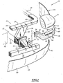
- a first front block 10 according to the invention is shown partially on the Figure 1 .
- This front block 10 comprises rigid structural elements 12 of the body, and a transverse structural front face 14, fixed to the body elements 12.
- the front unit 10 further comprises side wings 16, a front shield skin 18, and two flexible arms 20 for supporting an optical unit 22 attached to a region of the body elements 12 located at the front and at the front. distance from the front face 14, by means of a fixing lug 23.
- the body elements 12 comprise lower side members 24, upper longitudinal uprights 26 for supporting the wings 16, a transverse bumper beam 28 and shock absorbers 30 mounted longitudinally between the side members 24 and the beam 28. .
- Each side member 24 has at its front end located in contact with the absorbers 30, an end plate 32 for fixing.
- the front face 14 is fixed transversely to the side members 24, to the front of the engine and to the rear of the end plates 32 of the side members. It comprises an upper cross member 34 and a lower frame 36 for supporting a fan.
- the upper cross member 34 has a central region 38, located opposite the frame 36, and two lateral extensions 40 on which the longitudinal uprights 26 are attached.
- the frame 36 is integral with the cross member 34 and is located under the cross member 36. It has two vertical lateral uprights 42 extending between the cross member 34 and a side member 24.
- the front face 14 carries various vehicle equipment items such as a fan 44, a radiator and / or a heat exchanger (not shown).
- Each flexible arm 20 comprises a flexible body 50 around a substantially vertical axis, the body 50 having an inner end 52 attached to the body elements 12 at the front of the front face 14, and an outer end 54 on which is fixed a front edge of the wing 16.
- the inner end 52 of the flexible body comprises an end plate 56 for fixing to the body elements 12 extending in a transverse vertical plane.
- the flexible body 50 comprises an interior portion 58 for connection to the end plate 56, and an exterior portion 60 curved for supporting the optical unit 22.
- the portions 58, 60 define between them a vertical attenuation notch 62 opening towards the rear. and defining a pivot axis of the exterior portion 60 relative to the interior portion 58.
- the interior portion 58 extends longitudinally in front of the end plate 56.
- the outer part 60 is curved towards the rear and towards the outside of the vehicle.
- the outer end 54 is thus located behind the inner end 52.
- the outer part 60 has an upper surface 64 for supporting the optical unit 22 and a front surface 66 for supporting the skin 18.
- the upper surface 64 is substantially flat and horizontal. Indexing pins 68 protrude vertically with respect to the surface 64 to ensure the rigid fixing of the optical unit 22 on this surface 64.
- the front surface 68 is substantially perpendicular to the upper surface 64.
- Horizontal gutters 70 for positioning the skin 18 project forward from the front surface 68.
- the optical unit 22 is for example a monobloc optical unit integrating a flashing function and a main lighting part.
- the optical unit 22 rests on the surface 64 and is held in position on this surface by the indexing pins 68.
- each fixing lug 23 is attached to the bumper beam 28, facing a front plate 32.
- Each lug 23 thus comprises a foot 72 fixed to an upper surface of the beam 28 and a projection 74 for fixing the arm 20.
- the fixing projection 74 extends in a transverse vertical plane.
- the end plate 56 located at the inner end 52 of the arm is fixed to the front of the projection 74, for example by screwing or riveting.
- the wing 16 is formed by a body panel fixed at the rear on the body elements 12, and fixed along its front edge to the outer end 54 of the arm 20.
- Skin 18 comprises a substantially transverse central region 80 covering beam 28 at the front, and two side cheeks 82 covering arms 20 and the left and right ends of beam 28.
- the upper edge of the cheeks 80 is engaged in the gutters 70 to position the skin 18 relative to the optical unit 22.
- the front face 14 provided with its equipment 44 is mounted on the side members 24 of the vehicle by means of the uprights 42.
- the absorbers 30 are attached to the end plates 32 and the beam. bumper 28 is mounted in front of the absorbers 30.
- the fixing lugs 23 are attached to an upper surface of the beam 28.
- the end plates 58 located at the inner end 52 of the arms 20 are then applied to the front of the fixing protrusions 74 and then are fixed to these protrusions. 74 by screwing or riveting.
- optical units 22 are then placed on the bearing surfaces 64 of the arms 80 and are held in position on the surfaces 64.
- each wing 16 is fixed to the outer end 54 of an arm 20 and the upper edge of the cheeks 82 is introduced into the gutters 70 to be fixed on these gutters.
- Each arm 20 being flexible, it is able to deform around the notch 62, which automatically adjusts the clearances between the bodywork elements 16, 18 and the optical units 22.
- the exterior aesthetic appearance of the vehicle is therefore very satisfactory. .
- the arm 20 being fixed to the front of the front face 14, it is possible to provide wings 16 which extend notably to the front and to the side of the front face 14. Bulky vehicle templates can therefore be obtained.
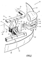
- the foot 72 of the fixing lugs 23 is fixed to the shock absorbers 30 located between the end plates 32 of the side members 24 and the bumper beam 28.
- each fixing lug 23 is integral with the end plate 32.
- the lug 23 comprises a fixing projection 74 integrally formed with the end plate 32.
- the lug 23 has no foot 72.
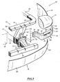
- the front unit does not have a structural front face 14. It comprises a cross member 34 carrying the fan 44, without a structural frame 36.
Landscapes
- Engineering & Computer Science (AREA)
- Mechanical Engineering (AREA)
- Chemical & Material Sciences (AREA)
- Combustion & Propulsion (AREA)
- Transportation (AREA)
- Body Structure For Vehicles (AREA)
Claims (5)
- Vorderstruktur (10) eines Kraftfahrzeugs der Bauart, die umfasst:- starre Karosserieelemente (12), die mindestens zwei Längsträger (24) und einen an den Längsträgern (24) befestigten Stroßfängerträger (28) aufweisen, wobei jeder Längsträger (24) eine vordere Platte (32) umfasst, die sich an seinem vorderen Ende befindet,- ein transversales Strukturorgan (14), das mindestens einen Ventilator und einen Wärmetauscher trägt, wobei das transversale Organ transversal auf den Karosserieelementen (12) hinter jeder vorderen Platte (32) befestigt ist, wobei das transversale Strukturorgan (14) bestimmt ist, vor dem Motor befestigt zu sein,- eine Stoßfängerverkleidung (18),- mindestens eine Karosserieplatte (16) und- zwei flexible Trägerarme (20) eines Optikblocks, wobei jeder flexible Arm (20) einen Optikblock (22) trägt und an der Stoßfängerverkleidung (18) und/oder an der Karosserieplatte (16) befestigt ist, wobei jeder flexible Arm imstande ist, die Spiele zwischen dem Optikblock und der Stoßfängerverkleidung oder jeder Karosserieplatte automatisch einzustellen,dadurch gekennzeichnet, dass jeder flexible Arm (20) in einem vorderen Bereich (28; 30) der Karosserieelemente (12) angebracht ist, die sich vor den vorderen Platten (32) eines Längsträgers beabstandet vom transversalen Strukturorgan (14) befindet, wobei der vorderen Bereich aus einem Stoßfängerträger (28) und einem Stoßabsorber (30) ausgewählt ist, der zwischen einem Stoßfängerträger (28) und einer vorderen Platte (32) eines Längsträgers (24) angeordnet ist.
- Vorderstruktur (10) nach Anspruch 1, dadurch gekennzeichnet, dass sie für jeden flexiblen Arm (20) eine Befestigungslasche (23) des Arms (20) umfasst, die eine Befestigungsfläche (72) an einem Karosserieelement (12) und eine Befestigungsfläche (74) am Arm (20) aufweist, die im Verhältnis zur Befestigungsfläche (72) am Karosserieelement (12) hervorsteht.
- Vorderstruktur (10) nach einem der vorangehenden Ansprüche, dadurch gekennzeichnet, dass der oder jeder Arm (20) einen flexiblen Verbindungskörper (50) umfasst, der sich zwischen einem inneren, auf den Karosserieelementen (12) befestigten Ende (52) und einem äußeren, auf der Stoßfängerverkleidung (18) und/oder der Karosserieplatte (16) befestigten Ende (54) erstreckt.
- Vorderstruktur (10) nach einem der vorangehenden Ansprüche, dadurch gekennzeichnet, dass das transversale Strukturorgan (14) eine transversale Vorderfläche ist, die einen transversalen Querträger (34) und einen mit dem Querträger (34) verbundenen Rahmen (36) umfasst, und sich unter dem Querträger (34) erstreckt.
- Kraftfahrzeug, dadurch gekennzeichnet, dass es eine Vorderstruktur (10) nach einem der vorangehenden Ansprüche umfasst.
Applications Claiming Priority (1)
| Application Number | Priority Date | Filing Date | Title |
|---|---|---|---|
| FR0609282A FR2907392B1 (fr) | 2006-10-23 | 2006-10-23 | Bloc avant de vehicule et vehicule automobile associe |
Publications (3)
| Publication Number | Publication Date |
|---|---|
| EP1916152A1 EP1916152A1 (de) | 2008-04-30 |
| EP1916152B1 EP1916152B1 (de) | 2015-12-09 |
| EP1916152B2 true EP1916152B2 (de) | 2020-11-25 |
Family
ID=37966447
Family Applications (1)
| Application Number | Title | Priority Date | Filing Date |
|---|---|---|---|
| EP07291263.7A Ceased EP1916152B2 (de) | 2006-10-23 | 2007-10-16 | Vorderstruktur eines Kraftfahrzeugs und damit ausgestattetes Kraftfahrzeug |
Country Status (2)
| Country | Link |
|---|---|
| EP (1) | EP1916152B2 (de) |
| FR (1) | FR2907392B1 (de) |
Families Citing this family (6)
| Publication number | Priority date | Publication date | Assignee | Title |
|---|---|---|---|---|
| DE102007033313A1 (de) * | 2007-07-18 | 2009-01-22 | Daimler Ag | Stoßfänger für einen Personenkraftwagen |
| FR2931443B1 (fr) * | 2008-05-21 | 2012-05-18 | Peugeot Citroen Automobiles Sa | Dispositif pour supporter la pare-choc arriere surmontee de deux feux arrieres d'un vehicule automobile et procede de montage du pare-choc |
| FR2943293B1 (fr) * | 2009-03-17 | 2011-04-15 | Peugeot Citroen Automobiles Sa | Poutre avant d'absorption de choc frontal comportant des pattes de fixation pour l'optique des projecteurs et vehicule equipe d'une telle poutre |
| CN111003064A (zh) * | 2019-12-05 | 2020-04-14 | 宁波吉利汽车研究开发有限公司 | 前防撞横梁和发动机罩锁支架的连接支架 |
| FR3122379A1 (fr) * | 2021-04-29 | 2022-11-04 | Psa Automobiles Sa | Ensemble comportant une poutre de parechoc et un support de projecteur |
| FR3140822A1 (fr) * | 2022-10-13 | 2024-04-19 | Psa Automobiles Sa | Support projecteur pour véhicule automobile |
Citations (1)
| Publication number | Priority date | Publication date | Assignee | Title |
|---|---|---|---|---|
| DE10237454B3 (de) † | 2002-08-13 | 2004-02-05 | Decoma (Germany) Gmbh | Frontend-Modul für ein Kraftfahrzeug |
Family Cites Families (13)
| Publication number | Priority date | Publication date | Assignee | Title |
|---|---|---|---|---|
| JP2898339B2 (ja) * | 1990-03-30 | 1999-05-31 | マツダ株式会社 | 自動車の前部車体構造及び車体組立方法 |
| US6386624B1 (en) * | 1998-10-29 | 2002-05-14 | Plastech | Front end assembly for an automotive vehicle |
| FR2820706B1 (fr) | 2001-02-15 | 2003-05-16 | Faurecia Ind | Ensemble de bloc avant de vehicule automobile comportant un dispositif ameliore de fixation des composants, et vehicule equipe d'un tel ensemble |
| FR2852569B1 (fr) | 2003-03-17 | 2006-04-21 | Module de face avant de vehicule automobile | |
| FR2864013B1 (fr) | 2003-12-19 | 2006-03-17 | Faurecia Bloc Avant | Ensemble de partie avant de vehicule automobile comportant des moyens perfectionnes de fixation et d'ajustement en position, et vehicule automobile pourvu d'un tel ensemble. |
| JP2005178705A (ja) | 2003-12-24 | 2005-07-07 | Mazda Motor Corp | 自動車の前部車体構造 |
| US7210733B2 (en) | 2004-04-22 | 2007-05-01 | Ford Global Technologies, Llc | Tubular support for shock tower in automobiles |
| FR2873652B1 (fr) * | 2004-08-02 | 2008-01-25 | Faurecia Bloc Avant | Ensemble de partie avant d'un vehicule automobile |
| FR2873649B1 (fr) | 2004-08-02 | 2006-11-24 | Faurecia Bloc Avant | Ensemble de bloc-avant de vehicule automobile |
| DE102005013107B3 (de) | 2005-03-18 | 2006-07-13 | Faurecia Kunststoffe Automobilsysteme Gmbh | Träger für die Fronteinheit eines Kraftfahrzeugs und Montageverfahren |
| FR2888197B1 (fr) * | 2005-07-08 | 2007-10-12 | Faurecia Bloc Avant | Ensemble de bloc avant de vehicule automobile correspondant. |
| FR2891797B1 (fr) * | 2005-10-06 | 2009-05-08 | Plastic Omnium Cie | Support pour positionner une piece de carrosserie et au moins un bloc optique sur un vehicule automobile. |
| DE102006026255A1 (de) | 2006-06-02 | 2007-12-06 | Peguform Gmbh | Stoßfängermodul |
-
2006
- 2006-10-23 FR FR0609282A patent/FR2907392B1/fr not_active Expired - Fee Related
-
2007
- 2007-10-16 EP EP07291263.7A patent/EP1916152B2/de not_active Ceased
Patent Citations (1)
| Publication number | Priority date | Publication date | Assignee | Title |
|---|---|---|---|---|
| DE10237454B3 (de) † | 2002-08-13 | 2004-02-05 | Decoma (Germany) Gmbh | Frontend-Modul für ein Kraftfahrzeug |
Also Published As
| Publication number | Publication date |
|---|---|
| EP1916152A1 (de) | 2008-04-30 |
| FR2907392A1 (fr) | 2008-04-25 |
| EP1916152B1 (de) | 2015-12-09 |
| FR2907392B1 (fr) | 2009-06-26 |
Similar Documents
| Publication | Publication Date | Title |
|---|---|---|
| EP0720935B1 (de) | Vorrichtung zur präzisen Positionierung eines Stossfängers zu einem Kotflügelteil eines Fahrzeuges | |
| EP1916152B2 (de) | Vorderstruktur eines Kraftfahrzeugs und damit ausgestattetes Kraftfahrzeug | |
| FR2820706A1 (fr) | Ensemble de bloc avant de vehicule automobile comportant un dispositif ameliore de fixation des composants, et vehicule equipe d'un tel ensemble | |
| EP1773648A1 (de) | Fronteinheit für ein kraftfahrzeug | |
| EP1623873B1 (de) | Vorderwagenaufbau eines Kraftfahrzeuges | |
| WO2014057217A1 (fr) | Procede de fabrication et de montage d'une partie avant d'un vehicule automobile | |
| EP1484216B1 (de) | Frontmodul für ein Fahrzeug mit Mitteln zur Selbstjustierung der Position der Beleuchtungseinheiten und zu diesem Zwecke vorgesehener abnehmbarer Einstellplatine, und Montageverfahren für ein solches Frontmodul | |
| FR2873650A1 (fr) | Structure de bloc-avant de vehicule automobile | |
| FR2953923A1 (fr) | Gabarit de controle de la caisse d'un vehicule automobile | |
| EP1861283A1 (de) | Oberer querträger für kraftfahrzeugfronteinheit | |
| EP1603787B1 (de) | Frontmodul eines fahrzeugs | |
| EP2132055B1 (de) | Verfahren zur Montage eines transversalen Unterstrukturelements und einer technischen Fronttafel | |
| JP4048827B2 (ja) | 車体前部組付け方法および組付け治具 | |
| EP3405382B1 (de) | Teil zur verstärkung eines unteren querträgers für eine fensteröffnung | |
| EP2145815B1 (de) | Einheit aus einem Kotflügel und einem tragenden Element für Kraftfahrzeug | |
| EP2173583B1 (de) | Vorrichtung zur anpassung der hülle der karosserie eines automobils | |
| WO2024061647A1 (fr) | Dispositif formant marchepied d'un véhicule automobile | |
| FR3142159A1 (fr) | Structure avant de véhicule automobile avec support d’essuie-glace | |
| FR3061121A1 (fr) | Face avant technique partiellement demontable. | |
| FR2940234A1 (fr) | Agencement pour le montage de la facade avant d'un vehicule automobile | |
| EP4541659A1 (de) | Befestigungsteil eines kraftfahrzeugscheinwerfers zur abstützung eines anschlags einer motorhaube des fahrzeugs und zugehörige haubenanschlagvorrichtung | |
| FR3148984A1 (fr) | Déflecteur aéraulique pour véhicule automobile | |
| FR2934982A1 (fr) | Module avant de vehicule automobile, procede de construction d'un vehicule automobile et vehicule automobile correspondant | |
| FR2942447A1 (fr) | Caisse de vehicule automobile et procede de realisation correspondant. | |
| FR2965532A1 (fr) | Ensemble et procede de montage d'attaches de ceinture de securite dans un vehicule. |
Legal Events
| Date | Code | Title | Description |
|---|---|---|---|
| PUAI | Public reference made under article 153(3) epc to a published international application that has entered the european phase |
Free format text: ORIGINAL CODE: 0009012 |
|
| AK | Designated contracting states |
Kind code of ref document: A1 Designated state(s): AT BE BG CH CY CZ DE DK EE ES FI FR GB GR HU IE IS IT LI LT LU LV MC MT NL PL PT RO SE SI SK TR |
|
| AX | Request for extension of the european patent |
Extension state: AL BA HR MK RS |
|
| 17P | Request for examination filed |
Effective date: 20080909 |
|
| 17Q | First examination report despatched |
Effective date: 20081010 |
|
| AKX | Designation fees paid |
Designated state(s): DE FR |
|
| GRAP | Despatch of communication of intention to grant a patent |
Free format text: ORIGINAL CODE: EPIDOSNIGR1 |
|
| INTG | Intention to grant announced |
Effective date: 20150605 |
|
| GRAS | Grant fee paid |
Free format text: ORIGINAL CODE: EPIDOSNIGR3 |
|
| GRAA | (expected) grant |
Free format text: ORIGINAL CODE: 0009210 |
|
| AK | Designated contracting states |
Kind code of ref document: B1 Designated state(s): DE FR |
|
| REG | Reference to a national code |
Ref country code: DE Ref legal event code: R096 Ref document number: 602007044159 Country of ref document: DE |
|
| REG | Reference to a national code |
Ref country code: DE Ref legal event code: R026 Ref document number: 602007044159 Country of ref document: DE |
|
| PLBI | Opposition filed |
Free format text: ORIGINAL CODE: 0009260 |
|
| REG | Reference to a national code |
Ref country code: DE Ref legal event code: R082 Ref document number: 602007044159 Country of ref document: DE Representative=s name: LAVOIX MUNICH, DE Ref country code: DE Ref legal event code: R082 Ref document number: 602007044159 Country of ref document: DE |
|
| 26 | Opposition filed |
Opponent name: MAGNA EXTERIORS GMBH Effective date: 20160812 |
|
| REG | Reference to a national code |
Ref country code: FR Ref legal event code: PLFP Year of fee payment: 10 |
|
| PLAX | Notice of opposition and request to file observation + time limit sent |
Free format text: ORIGINAL CODE: EPIDOSNOBS2 |
|
| PLBB | Reply of patent proprietor to notice(s) of opposition received |
Free format text: ORIGINAL CODE: EPIDOSNOBS3 |
|
| RAP2 | Party data changed (patent owner data changed or rights of a patent transferred) |
Owner name: FLEX-N-GATE FRANCE |
|
| REG | Reference to a national code |
Ref country code: FR Ref legal event code: PLFP Year of fee payment: 11 |
|
| RAP2 | Party data changed (patent owner data changed or rights of a patent transferred) |
Owner name: FLEX-N-GATE FRANCE |
|
| APBM | Appeal reference recorded |
Free format text: ORIGINAL CODE: EPIDOSNREFNO |
|
| APBP | Date of receipt of notice of appeal recorded |
Free format text: ORIGINAL CODE: EPIDOSNNOA2O |
|
| APAH | Appeal reference modified |
Free format text: ORIGINAL CODE: EPIDOSCREFNO |
|
| APBQ | Date of receipt of statement of grounds of appeal recorded |
Free format text: ORIGINAL CODE: EPIDOSNNOA3O |
|
| REG | Reference to a national code |
Ref country code: FR Ref legal event code: PLFP Year of fee payment: 12 |
|
| REG | Reference to a national code |
Ref country code: DE Ref legal event code: R082 Ref document number: 602007044159 Country of ref document: DE Representative=s name: LAVOIX MUNICH, DE |
|
| APBU | Appeal procedure closed |
Free format text: ORIGINAL CODE: EPIDOSNNOA9O |
|
| PUAH | Patent maintained in amended form |
Free format text: ORIGINAL CODE: 0009272 |
|
| STAA | Information on the status of an ep patent application or granted ep patent |
Free format text: STATUS: PATENT MAINTAINED AS AMENDED |
|
| PGFP | Annual fee paid to national office [announced via postgrant information from national office to epo] |
Ref country code: FR Payment date: 20200917 Year of fee payment: 14 |
|
| 27A | Patent maintained in amended form |
Effective date: 20201125 |
|
| AK | Designated contracting states |
Kind code of ref document: B2 Designated state(s): DE FR |
|
| REG | Reference to a national code |
Ref country code: DE Ref legal event code: R102 Ref document number: 602007044159 Country of ref document: DE |
|
| PGFP | Annual fee paid to national office [announced via postgrant information from national office to epo] |
Ref country code: DE Payment date: 20200917 Year of fee payment: 14 |
|
| REG | Reference to a national code |
Ref country code: DE Ref legal event code: R119 Ref document number: 602007044159 Country of ref document: DE |
|
| PG25 | Lapsed in a contracting state [announced via postgrant information from national office to epo] |
Ref country code: DE Free format text: LAPSE BECAUSE OF NON-PAYMENT OF DUE FEES Effective date: 20220503 |
|
| PG25 | Lapsed in a contracting state [announced via postgrant information from national office to epo] |
Ref country code: FR Free format text: LAPSE BECAUSE OF NON-PAYMENT OF DUE FEES Effective date: 20211031 |