EP1916152B2 - Front-end structure of a vehicle and associated automobile - Google Patents
Front-end structure of a vehicle and associated automobile Download PDFInfo
- Publication number
- EP1916152B2 EP1916152B2 EP07291263.7A EP07291263A EP1916152B2 EP 1916152 B2 EP1916152 B2 EP 1916152B2 EP 07291263 A EP07291263 A EP 07291263A EP 1916152 B2 EP1916152 B2 EP 1916152B2
- Authority
- EP
- European Patent Office
- Prior art keywords
- fixed
- arm
- transverse
- bumper
- body shell
- Prior art date
- Legal status (The legal status is an assumption and is not a legal conclusion. Google has not performed a legal analysis and makes no representation as to the accuracy of the status listed.)
- Expired - Fee Related
Links
Images
Classifications
-
- B—PERFORMING OPERATIONS; TRANSPORTING
- B62—LAND VEHICLES FOR TRAVELLING OTHERWISE THAN ON RAILS
- B62D—MOTOR VEHICLES; TRAILERS
- B62D25/00—Superstructure or monocoque structure sub-units; Parts or details thereof not otherwise provided for
- B62D25/08—Front or rear portions
- B62D25/082—Engine compartments
- B62D25/084—Radiator supports
-
- B—PERFORMING OPERATIONS; TRANSPORTING
- B60—VEHICLES IN GENERAL
- B60Q—ARRANGEMENT OF SIGNALLING OR LIGHTING DEVICES, THE MOUNTING OR SUPPORTING THEREOF OR CIRCUITS THEREFOR, FOR VEHICLES IN GENERAL
- B60Q1/00—Arrangement of optical signalling or lighting devices, the mounting or supporting thereof or circuits therefor
- B60Q1/02—Arrangement of optical signalling or lighting devices, the mounting or supporting thereof or circuits therefor the devices being primarily intended to illuminate the way ahead or to illuminate other areas of way or environments
- B60Q1/04—Arrangement of optical signalling or lighting devices, the mounting or supporting thereof or circuits therefor the devices being primarily intended to illuminate the way ahead or to illuminate other areas of way or environments the devices being headlights
- B60Q1/0408—Arrangement of optical signalling or lighting devices, the mounting or supporting thereof or circuits therefor the devices being primarily intended to illuminate the way ahead or to illuminate other areas of way or environments the devices being headlights built into the vehicle body, e.g. details concerning the mounting of the headlamps on the vehicle body
- B60Q1/0441—Arrangement of optical signalling or lighting devices, the mounting or supporting thereof or circuits therefor the devices being primarily intended to illuminate the way ahead or to illuminate other areas of way or environments the devices being headlights built into the vehicle body, e.g. details concerning the mounting of the headlamps on the vehicle body the housing being fastened onto the vehicle body using means other than screws
-
- B—PERFORMING OPERATIONS; TRANSPORTING
- B60—VEHICLES IN GENERAL
- B60Q—ARRANGEMENT OF SIGNALLING OR LIGHTING DEVICES, THE MOUNTING OR SUPPORTING THEREOF OR CIRCUITS THEREFOR, FOR VEHICLES IN GENERAL
- B60Q1/00—Arrangement of optical signalling or lighting devices, the mounting or supporting thereof or circuits therefor
- B60Q1/02—Arrangement of optical signalling or lighting devices, the mounting or supporting thereof or circuits therefor the devices being primarily intended to illuminate the way ahead or to illuminate other areas of way or environments
- B60Q1/04—Arrangement of optical signalling or lighting devices, the mounting or supporting thereof or circuits therefor the devices being primarily intended to illuminate the way ahead or to illuminate other areas of way or environments the devices being headlights
- B60Q1/0408—Arrangement of optical signalling or lighting devices, the mounting or supporting thereof or circuits therefor the devices being primarily intended to illuminate the way ahead or to illuminate other areas of way or environments the devices being headlights built into the vehicle body, e.g. details concerning the mounting of the headlamps on the vehicle body
- B60Q1/045—Arrangement of optical signalling or lighting devices, the mounting or supporting thereof or circuits therefor the devices being primarily intended to illuminate the way ahead or to illuminate other areas of way or environments the devices being headlights built into the vehicle body, e.g. details concerning the mounting of the headlamps on the vehicle body with provision for adjusting the alignment of the headlamp housing with respect to the vehicle body
Definitions
- the present invention relates to a front unit of a motor vehicle, according to the preamble of claim 1.
- WO 2007/140892 is part of the state of the art only under Article 54 (3) EPC 2000. It describes a vehicle front structure in which a structural member carrying a radiator is placed in front of the front side member plates.
- JP 03-284481 and WO 2004/085230 describe motor vehicle front units which include a rigid fixing of the optical units on the body of the motor vehicle.
- EP 1 702 834 according to the preamble and EP 1,623,873 describe flexible optical unit support arms fixed to the body of the motor vehicle.
- the front units of motor vehicles generally include a front face which has a central part and two side parts, a bumper, and a bumper skin forming a fairing of this bumper.
- the front units further comprise two arms each extending from the central part towards a respective lateral part, and forming members for supporting said bumper skin, and two optical units.
- Each optical unit is supported by a respective lateral part and has a lateral peripheral part adapted to cooperate with a complementary recess of a respective front wing part.
- a major difficulty encountered by automobile manufacturers consists in accurately positioning the optical units with respect to the appearance elements constituted by the fenders and the bumper skin. This adjustment is important because a lack of surface continuity of the visible part of the optical unit, that is to say of the glass, of the corresponding wing, and of the bumper skin significantly degrades the aesthetic quality. of the vehicle.
- precise adjustment of the position of the optical unit with respect to the fender and the bumper skin is difficult to maintain between the operation of mounting the optical units on the front face and the assembly operation. of the front unit fitted on the body of the motor vehicle.
- each optical unit is generally fixed at four points on the front face which constitutes a rigid part.
- each optical unit After assembly of each optical unit, they are mounted on the vehicle body and the front end of the corresponding bodywork fender is fixed to each of these optical units.
- the automobile manufacturer makes the adjustment of the position of the optical unit relative to the wing, by acting on two fixing points of the optical unit on the front face.
- a motor vehicle front unit comprising a front face, which has a central part and two side parts, a bumper skin, two flexible arms extending laterally and forming supports for the bumper skin, each of which has a first end connected to the central part and a second end intended to be connected to a front part of the body fender of the vehicle, and two optical units, each of which is rigidly fixed to a respective arm.
- the structure described in this document allows automatic and permanent positioning of the visible contours of the optical units with respect to the corresponding wing tips and to the bumper skin.
- each arm improves the aesthetic appearance of the vehicle by correcting the play between the optical unit, the bumper skin and each fender panel.
- each arm is fixed on a front surface of the front face, which is suitable for bodywork geometries in which the optical unit is close to the front face.
- An object of the invention is therefore to obtain front units of motor vehicles having different bodywork geometries, in particular for bodies strongly curved towards the front and towards the sides, while maintaining a satisfactory aesthetic appearance between the optical unit. , bumper skin and fenders.
- the invention relates to a front unit according to claim 1.
- the front unit according to the invention can comprise one or more of the characteristics of claims 2 to 4 taken in isolation or in any technically possible combination, among other things where the transverse structural member is a transverse front face comprising a cross member. transverse and a frame integral with the cross member, and extending under the cross member.
- a further subject of the invention is a motor vehicle according to claim 5.
- orientations are the usual orientations of a motor vehicle.
- front refers to the normal direction of movement of a vehicle. automobile and the position of a driver.
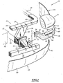
- a first front block 10 according to the invention is shown partially on the Figure 1 .
- This front block 10 comprises rigid structural elements 12 of the body, and a transverse structural front face 14, fixed to the body elements 12.
- the front unit 10 further comprises side wings 16, a front shield skin 18, and two flexible arms 20 for supporting an optical unit 22 attached to a region of the body elements 12 located at the front and at the front. distance from the front face 14, by means of a fixing lug 23.
- the body elements 12 comprise lower side members 24, upper longitudinal uprights 26 for supporting the wings 16, a transverse bumper beam 28 and shock absorbers 30 mounted longitudinally between the side members 24 and the beam 28. .
- Each side member 24 has at its front end located in contact with the absorbers 30, an end plate 32 for fixing.
- the front face 14 is fixed transversely to the side members 24, to the front of the engine and to the rear of the end plates 32 of the side members. It comprises an upper cross member 34 and a lower frame 36 for supporting a fan.
- the upper cross member 34 has a central region 38, located opposite the frame 36, and two lateral extensions 40 on which the longitudinal uprights 26 are attached.
- the frame 36 is integral with the cross member 34 and is located under the cross member 36. It has two vertical lateral uprights 42 extending between the cross member 34 and a side member 24.
- the front face 14 carries various vehicle equipment items such as a fan 44, a radiator and / or a heat exchanger (not shown).
- Each flexible arm 20 comprises a flexible body 50 around a substantially vertical axis, the body 50 having an inner end 52 attached to the body elements 12 at the front of the front face 14, and an outer end 54 on which is fixed a front edge of the wing 16.
- the inner end 52 of the flexible body comprises an end plate 56 for fixing to the body elements 12 extending in a transverse vertical plane.
- the flexible body 50 comprises an interior portion 58 for connection to the end plate 56, and an exterior portion 60 curved for supporting the optical unit 22.
- the portions 58, 60 define between them a vertical attenuation notch 62 opening towards the rear. and defining a pivot axis of the exterior portion 60 relative to the interior portion 58.
- the interior portion 58 extends longitudinally in front of the end plate 56.
- the outer part 60 is curved towards the rear and towards the outside of the vehicle.
- the outer end 54 is thus located behind the inner end 52.
- the outer part 60 has an upper surface 64 for supporting the optical unit 22 and a front surface 66 for supporting the skin 18.
- the upper surface 64 is substantially flat and horizontal. Indexing pins 68 protrude vertically with respect to the surface 64 to ensure the rigid fixing of the optical unit 22 on this surface 64.
- the front surface 68 is substantially perpendicular to the upper surface 64.
- Horizontal gutters 70 for positioning the skin 18 project forward from the front surface 68.
- the optical unit 22 is for example a monobloc optical unit integrating a flashing function and a main lighting part.
- the optical unit 22 rests on the surface 64 and is held in position on this surface by the indexing pins 68.
- each fixing lug 23 is attached to the bumper beam 28, facing a front plate 32.
- Each lug 23 thus comprises a foot 72 fixed to an upper surface of the beam 28 and a projection 74 for fixing the arm 20.
- the fixing projection 74 extends in a transverse vertical plane.
- the end plate 56 located at the inner end 52 of the arm is fixed to the front of the projection 74, for example by screwing or riveting.
- the wing 16 is formed by a body panel fixed at the rear on the body elements 12, and fixed along its front edge to the outer end 54 of the arm 20.
- Skin 18 comprises a substantially transverse central region 80 covering beam 28 at the front, and two side cheeks 82 covering arms 20 and the left and right ends of beam 28.
- the upper edge of the cheeks 80 is engaged in the gutters 70 to position the skin 18 relative to the optical unit 22.
- the front face 14 provided with its equipment 44 is mounted on the side members 24 of the vehicle by means of the uprights 42.
- the absorbers 30 are attached to the end plates 32 and the beam. bumper 28 is mounted in front of the absorbers 30.
- the fixing lugs 23 are attached to an upper surface of the beam 28.
- the end plates 58 located at the inner end 52 of the arms 20 are then applied to the front of the fixing protrusions 74 and then are fixed to these protrusions. 74 by screwing or riveting.
- optical units 22 are then placed on the bearing surfaces 64 of the arms 80 and are held in position on the surfaces 64.
- each wing 16 is fixed to the outer end 54 of an arm 20 and the upper edge of the cheeks 82 is introduced into the gutters 70 to be fixed on these gutters.
- Each arm 20 being flexible, it is able to deform around the notch 62, which automatically adjusts the clearances between the bodywork elements 16, 18 and the optical units 22.
- the exterior aesthetic appearance of the vehicle is therefore very satisfactory. .
- the arm 20 being fixed to the front of the front face 14, it is possible to provide wings 16 which extend notably to the front and to the side of the front face 14. Bulky vehicle templates can therefore be obtained.
- the foot 72 of the fixing lugs 23 is fixed to the shock absorbers 30 located between the end plates 32 of the side members 24 and the bumper beam 28.
- each fixing lug 23 is integral with the end plate 32.
- the lug 23 comprises a fixing projection 74 integrally formed with the end plate 32.
- the lug 23 has no foot 72.
- the front unit does not have a structural front face 14. It comprises a cross member 34 carrying the fan 44, without a structural frame 36.
Description
La présente invention concerne un bloc avant de véhicule automobile, selon le préambule de la revendication 1.The present invention relates to a front unit of a motor vehicle, according to the preamble of claim 1.
Les blocs avant de véhicules automobiles comportent généralement une face avant qui présente une partie centrale et deux parties latérales, un pare-chocs, et une peau de pare-chocs formant carénage de ce pare-chocs. Les blocs avant comprennent en outre deux bras s'étendant chacun de la partie centrale vers une partie latérale respective, et formant des organes de support de ladite peau dé pare-chocs, et deux blocs optiques. Chaque bloc optique est supporté par une partie latérale respective et présente une partie périphérique latérale adaptée pour coopérer avec un évidement complémentaire d'une partie avant d'aile respective.The front units of motor vehicles generally include a front face which has a central part and two side parts, a bumper, and a bumper skin forming a fairing of this bumper. The front units further comprise two arms each extending from the central part towards a respective lateral part, and forming members for supporting said bumper skin, and two optical units. Each optical unit is supported by a respective lateral part and has a lateral peripheral part adapted to cooperate with a complementary recess of a respective front wing part.
Une difficulté majeure rencontrée par les constructeurs automobiles consiste à positionner de façon précise les blocs optiques par rapport aux éléments d'aspect constitués par les ailes et la peau de pare-chocs. Cet ajustage est important du fait qu'un défaut de continuité de surface de la partie visible du bloc optique, c'est à dire de la glace, de l'aile correspondante, et de la peau de pare-chocs dégrade sensiblement la qualité esthétique du véhicule. En outre, un réglage précis de la position du bloc optique par rapport à l'aile et à la peau de pare-chocs est difficile à maintenir entre l'opération de montage des blocs optiques sur la face avant et l'opération d'assemblage du bloc avant équipé sur la caisse du véhicule automobile.A major difficulty encountered by automobile manufacturers consists in accurately positioning the optical units with respect to the appearance elements constituted by the fenders and the bumper skin. This adjustment is important because a lack of surface continuity of the visible part of the optical unit, that is to say of the glass, of the corresponding wing, and of the bumper skin significantly degrades the aesthetic quality. of the vehicle. In addition, precise adjustment of the position of the optical unit with respect to the fender and the bumper skin is difficult to maintain between the operation of mounting the optical units on the front face and the assembly operation. of the front unit fitted on the body of the motor vehicle.
Ces difficultés ont été accrues par la généralisation des blocs optiques monoblocs intégrant la fonction clignotant, alors qu'auparavant la partie formant le clignotant était ajustable par rapport à la partie principale du bloc optique, de sorte qu'il était relativement aisé de compenser des tolérances de positionnement.These difficulties have been increased by the generalization of monobloc optical units incorporating the indicator function, whereas previously the part forming the indicator was adjustable with respect to the main part of the optical unit, so that it was relatively easy to compensate for tolerances. positioning.
Dans le cas d'optiques monoblocs intégrant la fonction de clignotant, chaque bloc optique est généralement fixé en quatre points sur la face avant qui constitue une pièce rigide.In the case of monobloc optics integrating the flashing function, each optical unit is generally fixed at four points on the front face which constitutes a rigid part.
Après assemblage de chaque bloc optique, on les monte sur la caisse du véhicule et on fixe sur chacun de ces blocs optiques l'extrémité avant de l'aile de carrosserie correspondante.After assembly of each optical unit, they are mounted on the vehicle body and the front end of the corresponding bodywork fender is fixed to each of these optical units.
Dans une opération suivante, le constructeur automobile réalise le réglage de la position du bloc optique par rapport à l'aile, en agissant sur deux points de fixation du bloc optique sur la face avant.In a following operation, the automobile manufacturer makes the adjustment of the position of the optical unit relative to the wing, by acting on two fixing points of the optical unit on the front face.
L'inconvénient majeur de ce mode opératoire réside surtout dans cette opération de reprise en fin de montage, qui consiste à régler la position du bloc optique. En outre, ce réglage délicat doit être effectué pour tous les véhicules compte tenu des tolérances de fabrication et d'assemblage des différents éléments mis en jeu. Ces éléments étant également susceptibles de déformations plus ou moins importantes, les affleurements de surface obtenus par ces réglages ne sont pas stables dans le temps et peuvent nécessiter des réglages supplémentaires.The major drawback of this operating mode lies above all in this recovery operation at the end of assembly, which consists in adjusting the position of the optical unit. In addition, this delicate adjustment must be carried out for all vehicles taking into account the manufacturing and assembly tolerances of the various elements involved. These elements also being susceptible to more or less significant deformation, the surface outcrops obtained by these adjustments are not stable over time and may require additional adjustments.
A cet effet, on connaît dans le document
La structure décrite dans ce document permet un positionnement automatique et permanent des contours visibles des blocs optiques par rapport aux extrémités d'ailes correspondantes et à la peau de pare-chocs.The structure described in this document allows automatic and permanent positioning of the visible contours of the optical units with respect to the corresponding wing tips and to the bumper skin.
Les bras flexibles améliorent l'aspect esthétique du véhicule en corrigeant les jeux entre le bloc optique, la peau de pare-chocs et chaque panneau d'aile. Toutefois, dans cette structure, chaque bras est fixé sur une surface avant de la face avant, ce qui est adapté à des géométries de carrosserie dans lesquelles le bloc optique est proche de la face avant.The flexible arms improve the aesthetic appearance of the vehicle by correcting the play between the optical unit, the bumper skin and each fender panel. However, in this structure, each arm is fixed on a front surface of the front face, which is suitable for bodywork geometries in which the optical unit is close to the front face.
Un but de l'invention est donc d'obtenir des blocs avant de véhicules automobiles présentant des géométries de carrosserie différentes, notamment pour des carrosseries fortement bombées vers l'avant et vers les côtés, tout en conservant un aspect esthétique satisfaisant entre le bloc optique, la peau de pare-chocs et les ailes.An object of the invention is therefore to obtain front units of motor vehicles having different bodywork geometries, in particular for bodies strongly curved towards the front and towards the sides, while maintaining a satisfactory aesthetic appearance between the optical unit. , bumper skin and fenders.
A cet effet, l'invention a pour objet un bloc avant selon la revendication 1.To this end, the invention relates to a front unit according to claim 1.
Le bloc avant selon l'invention peut comprendre l'une ou plusieurs de caractéristiques des revendications 2 à 4 prise(s) isolément ou suivant toutes combinaisons techniquement possibles, entre autre où l'organe transversal de structure est une face avant transversale comprenant une traverse transversale et un cadre solidaire de la traverse, et s'étendant sous la traverse.The front unit according to the invention can comprise one or more of the characteristics of claims 2 to 4 taken in isolation or in any technically possible combination, among other things where the transverse structural member is a transverse front face comprising a cross member. transverse and a frame integral with the cross member, and extending under the cross member.
L'invention a en outre pour objet un véhicule automobile selon la revendication 5.A further subject of the invention is a motor vehicle according to claim 5.
L'invention sera mieux comprise à la lecture de la description qui va suivre, donnée uniquement à titre d'exemple, et faite en se référant aux dessins annexés, sur lesquels :
- la
Figure 1 est une vue schématique partielle en perspective de trois-quarts face d'un premier bloc avant selon l'invention ; - la
Figure 2 est une vue analogue à laFigure 1 d'un deuxième bloc avant selon l'invention et ; - la
Figure 3 est une vue analogue à laFigure 1 d'un troisième bloc avant ne faisant pas partie de l'invention.
- the
Figure 1 is a partial schematic perspective three-quarter front view of a first front unit according to the invention; - the
Figure 2 is a view analogous toFigure 1 a second front unit according to the invention and; - the
Figure 3 is a view analogous toFigure 1 of a third front unit not forming part of the invention.
Dans tout ce qui suit, les orientations sont les orientations habituelles d'un véhicule automobile. Ainsi, les termes « avant », « arrière », « supérieur », « inférieur », « extérieur », « intérieur », « gauche », « droite », s'entendent par rapport au sens normal de circulation d'un véhicule automobile et à la position d'un conducteur.In what follows, the orientations are the usual orientations of a motor vehicle. Thus, the terms "front", "rear", "upper", "lower", "exterior", "interior", "left", "right" are understood in relation to the normal direction of movement of a vehicle. automobile and the position of a driver.
Un premier bloc avant 10 selon l'invention est représenté partiellement sur la
Le bloc avant 10 comprend en outre des ailes latérales 16, une peau avant 18 de bouclier, et deux bras souples 20 de support d'un bloc optique 22 rapportés sur une région des éléments de caisse 12 située à l'avant et à l'écart de la face avant 14, par l'intermédiaire d'une patte de fixation 23.The
De manière classique, les éléments de caisse 12 comprennent des longerons 24 inférieurs, des montants 26 supérieurs longitudinaux de support des ailes 16, une poutre 28 transversale de pare-chocs et des absorbeurs 30 de chocs montés longitudinalement entre les longerons 24 et la poutre 28.Conventionally, the
Chaque longeron 24 présente à son extrémité avant située au contact des absorbeurs 30, une platine terminale 32 de fixation.Each
La face avant 14 est fixée transversalement sur les longerons 24, à l'avant du moteur et à l'arrière des platines terminales 32 des longerons. Elle comprend une traverse supérieure 34 et un cadre inférieur 36 de support d'un ventilateur.The
La traverse supérieure 34 présente une région centrale 38, située en regard du cadre 36, et deux prolongements latéraux 40 sur lesquels sont rapportés les montants longitudinaux 26.The
Le cadre 36 est solidaire de la traverse 34 et est situé sous la traverse 36. Il présente deux montants latéraux verticaux 42 s'étendant entre la traverse 34 et un longeron 24.The
Dans cet exemple, la face avant 14 porte divers équipements du véhicule comme un ventilateur 44, un radiateur et/ou un échangeur de chaleur (non représenté).In this example, the
Chaque bras souple 20 comprend un corps 50 flexible autour d'un axe sensiblement vertical, le corps 50 présentant une extrémité intérieure 52 rapportée sur les éléments de caisse 12 à l'avant de la face avant 14, et une extrémité extérieure 54 sur laquelle est fixé un bord avant de l'aile 16.Each
L'extrémité intérieure 52 du corps flexible comprend une plaque terminale 56 de fixation sur les éléments de caisse 12 s'étendant dans un plan vertical transversal.The
Le corps flexible 50 comprend une partie intérieure 58 de liaison à la plaque terminale 56, et une partie extérieure 60 galbée de support du bloc optique 22. Les parties 58, 60 définissent entre elles une encoche verticale 62 d'affaiblissement débouchant vers l'arrière et définissant un axe de pivotement de la partie extérieure 60 par rapport à la partie intérieure 58.The
La partie intérieure 58 s'étend longitudinalement à l'avant de la plaque terminale 56.The
La partie extérieure 60 est galbée vers l'arrière et vers l'extérieur du véhicule. L'extrémité extérieure 54 est ainsi située à l'arrière de l'extrémité intérieure 52.The
La partie extérieure 60 présente une surface supérieure 64 d'appui du bloc optique 22 et une surface avant 66 de support de la peau 18.The
La surface supérieure 64 est sensiblement plane et horizontale. Des pions d'indexation 68 font saillie verticalement par rapport à la surface 64 pour assurer la fixation rigide du bloc optique 22 sur cette surface 64.The
La surface avant 68 est sensiblement perpendiculaire à la surface supérieure 64. Des gouttières horizontales 70 de positionnement de la peau 18 font saillie à l'avant de la surface avant 68.The
Le bloc optique 22 est par exemple un bloc optique monobloc intégrant une fonction clignotant et une partie principale d'éclairage. Le bloc optique 22 repose en appui sur la surface 64 et est maintenu en position sur cette surface par les pions d'indexation 68.The
Dans cet exemple, chaque patte de fixation 23 est rapportée sur la poutre de pare-chocs 28, en regard d'une platine avant 32. Chaque patte 23 comprend ainsi un pied 72 fixé sur une surface supérieure de la poutre 28 et une saillie 74 de fixation du bras 20. La saillie de fixation 74 s'étend dans un plan vertical transversal. La plaque terminale 56 située à l'extrémité intérieure 52 du bras est fixée à l'avant de la saillie 74, par exemple par vissage ou rivetage.In this example, each fixing
L'aile 16 est formée par un panneau de carrosserie fixé à l'arrière sur les éléments de caisse 12, et fixée le long de son bord avant à l'extrémité extérieure 54 du bras 20.The
La peau 18 comprend une région centrale 80 sensiblement transversale couvrant la poutre 28 à l'avant, et deux joues latérales 82 couvrant les bras 20 et les extrémités gauche et droite de la poutre 28.
Le bord supérieur des joues 80 est engagé dans les gouttières 70 pour positionner la peau 18 par rapport au bloc optique 22.The upper edge of the
Un procédé de montage de la première face avant 10 selon l'invention va maintenant être décrit.A method of mounting the first
Initialement, la face avant 14 munie de ses équipements 44 est montée sur les longerons 24 du véhicule par l'intermédiaire des montants 42. Puis, les absorbeurs 30 sont rapportés sur les platines terminales 32 et la poutre de pare-chocs 28 est montée à l'avant des absorbeurs 30.Initially, the
Ensuite, les pattes de fixation 23 sont rapportées sur une surface supérieure de la poutre 28. Les plaques terminales 58 situées à l'extrémité intérieure 52 des bras 20 sont alors appliquées à l'avant des saillies de fixation 74 puis sont fixées sur ces saillies 74 par vissage ou par rivetage.Then, the fixing lugs 23 are attached to an upper surface of the
Les blocs optiques 22 sont ensuite placés sur les surfaces d'appui 64 des bras 80 et sont maintenus en position sur les surfaces 64.The
Puis, les éléments de carrosserie comme les ailes 16 et la peau 18 de pare-chocs sont fixés sur la caisse. Le bord avant de chaque aile 16 est fixé à l'extrémité extérieure 54 d'un bras 20 et le bord supérieur des joues 82 est introduit dans les gouttières 70 pour être fixé sur ces gouttières.Then, the bodywork elements such as the
Chaque bras 20 étant souple, il est apte à se déformer autour de l'encoche 62, ce qui ajuste automatiquement les jeux entre les éléments de carrosserie 16, 18 et les blocs optiques 22. L'aspect esthétique extérieur du véhicule est donc très satisfaisant.Each
En outre, le bras 20 étant fixé à l'avant de la face avant 14, il est possible de prévoir des ailes 16 qui s'étendent notablement à l'avant et sur le côté de la face avant 14. Des gabarits volumineux de véhicules peuvent donc être obtenus.In addition, the
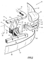
Dans la variante représentée sur la
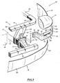
Dans la variante représentée sur la
Dans une autre variante (non représentée), le bloc avant est dépourvu de face avant structurelle 14. Il comprend une traverse 34 portant le ventilateur 44, sans cadre structurel 36.In another variant (not shown), the front unit does not have a structural
Claims (5)
- A motor vehicle front end (10), of the type comprising:- rigid body shell elements (12) including at least two girders (24) and a bumper beam (28) fixed on the girders (24), each girder (24) comprising a front plate (32) situated at its front end;- a transverse structural member (14) bearing at least a fan and a heat exchanger, the transverse member being fixed transversely on the body shell elements (12) behind each front plate (32); the transverse structural member (14) being designed to be fixed to the front of the engine;- a bumper skin (18);- at least one body panel (16); and- two flexible arms (20) for supporting a vehicle lamp (22), each flexible arm (20) bearing a vehicle lamp (22) and being fastened to the bumper skin (18) and/or to the body panel (16); each flexible arm being able to adjust the clearance automatically between the vehicle lamp and the bumper skin or each body panel;characterized in that each flexible arm (20) is connected on a front region (28; 30) of the body shell elements (12) situated in front of the front girder platens (32), away from the transverse structural member (14), the region having been chosen from among a bumper beam (28) and a shock absorber (30) inserted between a bumper beam (28) and a front platen (32) of a girder (24).
- The front end (10) according to claim 1, characterized in that it comprises, for each flexible arm (20), a fastening tab (23) of the arm (20) having a surface (72) for fastening to a body shell element (12) and a surface (74) for fastening to the arm (20) that protrudes relative to the fastening surface (72) to the body shell element (12).
- The front end (10) according to any one of the preceding claims, characterized in that the or each arm (20) comprises a flexible intermediate body (50) extending between an inner end (52) fixed on the body shell elements (12) and an outer end (54) fixed on the bumper skin (18) and/or the body panel (16).
- The front end (10) according to any one of the preceding claims, characterized in that the transverse structural member (14) is a transverse front face comprising a transverse cross-member (34) and a frame (36) fixed to the cross-member (34), and extending below the cross-member (34).
- A motor vehicle, characterized in that it comprises a front end (10) according to any one of the preceding claims.
Applications Claiming Priority (1)
| Application Number | Priority Date | Filing Date | Title |
|---|---|---|---|
| FR0609282A FR2907392B1 (en) | 2006-10-23 | 2006-10-23 | FRONT BLOCK OF VEHICLE AND ASSOCIATED MOTOR VEHICLE |
Publications (3)
| Publication Number | Publication Date |
|---|---|
| EP1916152A1 EP1916152A1 (en) | 2008-04-30 |
| EP1916152B1 EP1916152B1 (en) | 2015-12-09 |
| EP1916152B2 true EP1916152B2 (en) | 2020-11-25 |
Family
ID=37966447
Family Applications (1)
| Application Number | Title | Priority Date | Filing Date |
|---|---|---|---|
| EP07291263.7A Expired - Fee Related EP1916152B2 (en) | 2006-10-23 | 2007-10-16 | Front-end structure of a vehicle and associated automobile |
Country Status (2)
| Country | Link |
|---|---|
| EP (1) | EP1916152B2 (en) |
| FR (1) | FR2907392B1 (en) |
Families Citing this family (5)
| Publication number | Priority date | Publication date | Assignee | Title |
|---|---|---|---|---|
| DE102007033313A1 (en) * | 2007-07-18 | 2009-01-22 | Daimler Ag | Bumper for a passenger car |
| FR2931443B1 (en) * | 2008-05-21 | 2012-05-18 | Peugeot Citroen Automobiles Sa | DEVICE FOR SUPPORTING THE REAR BUMPER OVERLOADED BY TWO REAR LIGHTS OF A MOTOR VEHICLE AND METHOD OF MOUNTING THE BUMPER |
| FR2943293B1 (en) * | 2009-03-17 | 2011-04-15 | Peugeot Citroen Automobiles Sa | FRONT SHOCK ABSORPTION BEFORE BEAM COMPRISING FASTENING LEGS FOR THE OPTICS OF THE PROJECTORS AND VEHICLE EQUIPPED WITH SUCH A BEAM |
| CN111003064A (en) * | 2019-12-05 | 2020-04-14 | 宁波吉利汽车研究开发有限公司 | Connecting bracket for front anti-collision beam and engine hood lock bracket |
| FR3122379A1 (en) * | 2021-04-29 | 2022-11-04 | Psa Automobiles Sa | Set comprising a bumper beam and a projector support |
Citations (1)
| Publication number | Priority date | Publication date | Assignee | Title |
|---|---|---|---|---|
| DE10237454B3 (en) † | 2002-08-13 | 2004-02-05 | Decoma (Germany) Gmbh | Front end module for vehicle has auxiliary element extending upwards from transverse bumper (fender) carrier |
Family Cites Families (13)
| Publication number | Priority date | Publication date | Assignee | Title |
|---|---|---|---|---|
| JP2898339B2 (en) * | 1990-03-30 | 1999-05-31 | マツダ株式会社 | Vehicle front body structure and vehicle body assembly method |
| US6386624B1 (en) * | 1998-10-29 | 2002-05-14 | Plastech | Front end assembly for an automotive vehicle |
| FR2820706B1 (en) | 2001-02-15 | 2003-05-16 | Faurecia Ind | FRONT BLOCK ASSEMBLY OF A MOTOR VEHICLE COMPRISING AN IMPROVED DEVICE FOR FIXING THE COMPONENTS, AND VEHICLE PROVIDED WITH SUCH AN ASSEMBLY |
| FR2852569B1 (en) | 2003-03-17 | 2006-04-21 | FRONT PANEL MODULE FOR MOTOR VEHICLE | |
| FR2864013B1 (en) | 2003-12-19 | 2006-03-17 | Faurecia Bloc Avant | FRONT CAR PART ASSEMBLY COMPRISING ENHANCED FIXING AND ADJUSTING MEANS IN POSITION, AND MOTOR VEHICLE PROVIDED WITH SUCH AN ASSEMBLY. |
| JP2005178705A (en) | 2003-12-24 | 2005-07-07 | Mazda Motor Corp | Front body structure of automobile |
| US7210733B2 (en) | 2004-04-22 | 2007-05-01 | Ford Global Technologies, Llc | Tubular support for shock tower in automobiles |
| FR2873652B1 (en) * | 2004-08-02 | 2008-01-25 | Faurecia Bloc Avant | FRONT ASSEMBLY OF A MOTOR VEHICLE |
| FR2873649B1 (en) | 2004-08-02 | 2006-11-24 | Faurecia Bloc Avant | FRONT BLOCK ASSEMBLY OF MOTOR VEHICLE |
| DE102005013107B3 (en) | 2005-03-18 | 2006-07-13 | Faurecia Kunststoffe Automobilsysteme Gmbh | Support for a front unit/safety bumper on a motor vehicle has a support part for connecting to the vehicle's chassis and left and right mounting parts |
| FR2888197B1 (en) * | 2005-07-08 | 2007-10-12 | Faurecia Bloc Avant | FRONT BLOCK ASSEMBLY OF A CORRESPONDING MOTOR VEHICLE. |
| FR2891797B1 (en) * | 2005-10-06 | 2009-05-08 | Plastic Omnium Cie | SUPPORT FOR POSITIONING A BODY COMPONENT AND AT LEAST ONE OPTICAL BLOCK ON A MOTOR VEHICLE. |
| DE102006026255A1 (en) | 2006-06-02 | 2007-12-06 | Peguform Gmbh | bumper module |
-
2006
- 2006-10-23 FR FR0609282A patent/FR2907392B1/en not_active Expired - Fee Related
-
2007
- 2007-10-16 EP EP07291263.7A patent/EP1916152B2/en not_active Expired - Fee Related
Patent Citations (1)
| Publication number | Priority date | Publication date | Assignee | Title |
|---|---|---|---|---|
| DE10237454B3 (en) † | 2002-08-13 | 2004-02-05 | Decoma (Germany) Gmbh | Front end module for vehicle has auxiliary element extending upwards from transverse bumper (fender) carrier |
Also Published As
| Publication number | Publication date |
|---|---|
| FR2907392A1 (en) | 2008-04-25 |
| FR2907392B1 (en) | 2009-06-26 |
| EP1916152B1 (en) | 2015-12-09 |
| EP1916152A1 (en) | 2008-04-30 |
Similar Documents
| Publication | Publication Date | Title |
|---|---|---|
| EP1623873B1 (en) | Vehicle front body structure | |
| EP0720935B1 (en) | Device for precise positioning of a bumper to a vehicle fender portion | |
| FR2820706A1 (en) | FRONT BLOCK ASSEMBLY OF A MOTOR VEHICLE COMPRISING AN IMPROVED DEVICE FOR FIXING THE COMPONENTS, AND VEHICLE PROVIDED WITH SUCH AN ASSEMBLY | |
| EP1773648A1 (en) | Motor vehicle font unit | |
| EP1916152B2 (en) | Front-end structure of a vehicle and associated automobile | |
| EP2906443A1 (en) | Method for producing and installing a front end of a motor vehicle | |
| WO2006100379A1 (en) | Upper cross-member for motor vehicle front unit | |
| EP2603415B1 (en) | Assembly process for a front suspension and craddle onto the chassis of a vehicle | |
| FR2873650A1 (en) | Front unit structure for motor vehicle, has two flexible brackets whose ends, connected to central part of front side, are connected with each other by horizontal reinforcement on which central zone of bumper skin is supported | |
| EP1484216A1 (en) | Front module for vehicle with optical blocks position self-adjusting means provided with removable adjustment platinum and method for mounting thereof | |
| FR2953923A1 (en) | Template for checking body shell of motor vehicle, has single-piece bracket comprising interfaces positioned with respect to shell, and checking zones to simultaneously check multiple functional elements of front and/or rear face of shell | |
| FR3027580A1 (en) | RANGE OF AT LEAST TWO TYPES OF MOTOR VEHICLE COMPRISING A SHEET PAVILION OR A GLASS PAVILION | |
| EP1101691A1 (en) | Front quarter fixation on cross member | |
| EP2132055B1 (en) | Method for mounting a transverse understructure member and a technical front panel | |
| EP1603787B1 (en) | Front panel module for motor vehicle | |
| EP3405382B1 (en) | Part for reinforcing a lower crossbeam for a window opening | |
| JP4048827B2 (en) | Body front part assembly method and assembly jig | |
| EP2145815B1 (en) | Assembly of a wing and a supporting element for an automobile | |
| EP2173583B1 (en) | Device for conforming the skin of the bodywork of an automobile | |
| FR3139787A1 (en) | Device forming a step of a motor vehicle | |
| FR2940234A1 (en) | Front facade element e.g. headlamp, fixing arrangement for motor vehicle, has transverse gauge extending across width of motor vehicle in one direction so as to allow precise positioning of front facade element of motor vehicle | |
| EP2080666A1 (en) | Front block of an automobile with self-centring headlight | |
| FR3061121A1 (en) | TECHNICAL FRONT PANEL PARTIALLY REMOVABLE. | |
| FR2965532A1 (en) | Assembly for mounting safety belt attachments in motor vehicle, has cross-piece extending above floor and displaced along longitudinal direction of motor vehicle in positions, where cross-piece comprises ends connected to side elements | |
| FR2942447A1 (en) | AUTOMOTIVE VEHICLE BODY AND CORRESPONDING REALIZATION METHOD. |
Legal Events
| Date | Code | Title | Description |
|---|---|---|---|
| PUAI | Public reference made under article 153(3) epc to a published international application that has entered the european phase |
Free format text: ORIGINAL CODE: 0009012 |
|
| AK | Designated contracting states |
Kind code of ref document: A1 Designated state(s): AT BE BG CH CY CZ DE DK EE ES FI FR GB GR HU IE IS IT LI LT LU LV MC MT NL PL PT RO SE SI SK TR |
|
| AX | Request for extension of the european patent |
Extension state: AL BA HR MK RS |
|
| 17P | Request for examination filed |
Effective date: 20080909 |
|
| 17Q | First examination report despatched |
Effective date: 20081010 |
|
| AKX | Designation fees paid |
Designated state(s): DE FR |
|
| GRAP | Despatch of communication of intention to grant a patent |
Free format text: ORIGINAL CODE: EPIDOSNIGR1 |
|
| INTG | Intention to grant announced |
Effective date: 20150605 |
|
| GRAS | Grant fee paid |
Free format text: ORIGINAL CODE: EPIDOSNIGR3 |
|
| GRAA | (expected) grant |
Free format text: ORIGINAL CODE: 0009210 |
|
| AK | Designated contracting states |
Kind code of ref document: B1 Designated state(s): DE FR |
|
| REG | Reference to a national code |
Ref country code: DE Ref legal event code: R096 Ref document number: 602007044159 Country of ref document: DE |
|
| REG | Reference to a national code |
Ref country code: DE Ref legal event code: R026 Ref document number: 602007044159 Country of ref document: DE |
|
| PLBI | Opposition filed |
Free format text: ORIGINAL CODE: 0009260 |
|
| REG | Reference to a national code |
Ref country code: DE Ref legal event code: R082 Ref document number: 602007044159 Country of ref document: DE Representative=s name: LAVOIX MUNICH, DE Ref country code: DE Ref legal event code: R082 Ref document number: 602007044159 Country of ref document: DE |
|
| 26 | Opposition filed |
Opponent name: MAGNA EXTERIORS GMBH Effective date: 20160812 |
|
| REG | Reference to a national code |
Ref country code: FR Ref legal event code: PLFP Year of fee payment: 10 |
|
| PLAX | Notice of opposition and request to file observation + time limit sent |
Free format text: ORIGINAL CODE: EPIDOSNOBS2 |
|
| PLBB | Reply of patent proprietor to notice(s) of opposition received |
Free format text: ORIGINAL CODE: EPIDOSNOBS3 |
|
| RAP2 | Party data changed (patent owner data changed or rights of a patent transferred) |
Owner name: FLEX-N-GATE FRANCE |
|
| REG | Reference to a national code |
Ref country code: FR Ref legal event code: PLFP Year of fee payment: 11 |
|
| RAP2 | Party data changed (patent owner data changed or rights of a patent transferred) |
Owner name: FLEX-N-GATE FRANCE |
|
| APBM | Appeal reference recorded |
Free format text: ORIGINAL CODE: EPIDOSNREFNO |
|
| APBP | Date of receipt of notice of appeal recorded |
Free format text: ORIGINAL CODE: EPIDOSNNOA2O |
|
| APAH | Appeal reference modified |
Free format text: ORIGINAL CODE: EPIDOSCREFNO |
|
| APBQ | Date of receipt of statement of grounds of appeal recorded |
Free format text: ORIGINAL CODE: EPIDOSNNOA3O |
|
| REG | Reference to a national code |
Ref country code: FR Ref legal event code: PLFP Year of fee payment: 12 |
|
| REG | Reference to a national code |
Ref country code: DE Ref legal event code: R082 Ref document number: 602007044159 Country of ref document: DE Representative=s name: LAVOIX MUNICH, DE |
|
| APBU | Appeal procedure closed |
Free format text: ORIGINAL CODE: EPIDOSNNOA9O |
|
| PUAH | Patent maintained in amended form |
Free format text: ORIGINAL CODE: 0009272 |
|
| STAA | Information on the status of an ep patent application or granted ep patent |
Free format text: STATUS: PATENT MAINTAINED AS AMENDED |
|
| PGFP | Annual fee paid to national office [announced via postgrant information from national office to epo] |
Ref country code: FR Payment date: 20200917 Year of fee payment: 14 |
|
| 27A | Patent maintained in amended form |
Effective date: 20201125 |
|
| AK | Designated contracting states |
Kind code of ref document: B2 Designated state(s): DE FR |
|
| REG | Reference to a national code |
Ref country code: DE Ref legal event code: R102 Ref document number: 602007044159 Country of ref document: DE |
|
| PGFP | Annual fee paid to national office [announced via postgrant information from national office to epo] |
Ref country code: DE Payment date: 20200917 Year of fee payment: 14 |
|
| REG | Reference to a national code |
Ref country code: DE Ref legal event code: R119 Ref document number: 602007044159 Country of ref document: DE |
|
| PG25 | Lapsed in a contracting state [announced via postgrant information from national office to epo] |
Ref country code: DE Free format text: LAPSE BECAUSE OF NON-PAYMENT OF DUE FEES Effective date: 20220503 |
|
| PG25 | Lapsed in a contracting state [announced via postgrant information from national office to epo] |
Ref country code: FR Free format text: LAPSE BECAUSE OF NON-PAYMENT OF DUE FEES Effective date: 20211031 |