EP1914770B1 - Dispositif de détection de la position rélative de deux éléments à intégration améliorée - Google Patents
Dispositif de détection de la position rélative de deux éléments à intégration améliorée Download PDFInfo
- Publication number
- EP1914770B1 EP1914770B1 EP07301443.3A EP07301443A EP1914770B1 EP 1914770 B1 EP1914770 B1 EP 1914770B1 EP 07301443 A EP07301443 A EP 07301443A EP 1914770 B1 EP1914770 B1 EP 1914770B1
- Authority
- EP
- European Patent Office
- Prior art keywords
- door
- frame
- leaf
- opening
- electrical circuit
- Prior art date
- Legal status (The legal status is an assumption and is not a legal conclusion. Google has not performed a legal analysis and makes no representation as to the accuracy of the status listed.)
- Active
Links
Images


Classifications
-
- H—ELECTRICITY
- H01—ELECTRIC ELEMENTS
- H01H—ELECTRIC SWITCHES; RELAYS; SELECTORS; EMERGENCY PROTECTIVE DEVICES
- H01H3/00—Mechanisms for operating contacts
- H01H3/02—Operating parts, i.e. for operating driving mechanism by a mechanical force external to the switch
- H01H3/16—Operating parts, i.e. for operating driving mechanism by a mechanical force external to the switch adapted for actuation at a limit or other predetermined position in the path of a body, the relative movement of switch and body being primarily for a purpose other than the actuation of the switch, e.g. for a door switch, a limit switch, a floor-levelling switch of a lift
- H01H3/161—Operating parts, i.e. for operating driving mechanism by a mechanical force external to the switch adapted for actuation at a limit or other predetermined position in the path of a body, the relative movement of switch and body being primarily for a purpose other than the actuation of the switch, e.g. for a door switch, a limit switch, a floor-levelling switch of a lift for actuation by moving a closing member, e.g. door, cover or lid
-
- G—PHYSICS
- G08—SIGNALLING
- G08B—SIGNALLING SYSTEMS, e.g. PERSONAL CALLING SYSTEMS; ORDER TELEGRAPHS; ALARM SYSTEMS
- G08B13/00—Burglar, theft or intruder alarms
- G08B13/02—Mechanical actuation
- G08B13/08—Mechanical actuation by opening, e.g. of door, of window, of drawer, of shutter, of curtain, of blind
-
- H—ELECTRICITY
- H01—ELECTRIC ELEMENTS
- H01H—ELECTRIC SWITCHES; RELAYS; SELECTORS; EMERGENCY PROTECTIVE DEVICES
- H01H3/00—Mechanisms for operating contacts
- H01H3/02—Operating parts, i.e. for operating driving mechanism by a mechanical force external to the switch
- H01H3/14—Operating parts, i.e. for operating driving mechanism by a mechanical force external to the switch adapted for operation by a part of the human body other than the hand, e.g. by foot
- H01H3/141—Cushion or mat switches
- H01H3/142—Cushion or mat switches of the elongated strip type
Definitions
- the present invention relates to a device for detecting the position of two movable elements relative to each other whose integration is improved, in particular to a sensor intended to be implemented in assistance devices or monitoring, alarm type.
- the detection devices or sensor of a relative position of two elements of known type are interposed between the two elements and capture a modification of the parameters of the environment, for example because of a displacement of a moving part in the sensor .
- the opening of the door causes the illumination of the bulb which is disposed inside the refrigerator.
- the sensor is formed of a pin held in contact with the door by a spring. The displacement of this pin causes, when the door is closed, the opening of the electrical supply circuit of the bulb.
- the nipple moves in the opposite position, causing the closure of the electrical circuit and the power supply of the bulb and its illumination.
- the electrical circuit is attached to the refrigerator structure.
- the document EP 1 014 322 B1 discloses a device for breaking a rolling shutter closing an opening.
- This device comprises a sensor on the lower blade of the flap to inform of the position of the lower blade relative to the lower frame of the flap.
- This sensor is formed by a protruding nipple of the lower blade. When the shutter is closed, it is in contact with the lower frame of the opening. The pin then occupies a depressed position, and no information is sent by radio wave to a radio receiver.
- the senor according to the present invention comprises an electric circuit able to be opened and closed according to the position of the two elements, at least one of the elements being an electrical conductor forming part of an electrical circuit, the approximation or the distance from the other element causing the closing or opening of an electrical circuit.
- the present invention has the advantage of offering a very robust detection device, since it is not reported on the device equipped, but integrated in the less in part to one of the elements whose relative position one wants to detect.
- the present invention therefore, mainly relates to a device for detecting a relative position of a first element, having a main mechanical function, and a second element, comprising an electrical circuit whose opening and closing correspond respectively to a first and a second position of the first and second elements relative to each other, wherein at least the first element forms part of the electrical circuit.
- the term "element having a first main mechanical function" an element that performs any mechanical function.
- This may be, for example a support function in the case of a door frame, gripping, in the case in particular of a door handle, suspension or hooking, in the case for example of an object hooking means.
- a support element such as a console, cleats, etc.
- the first and second positions also include a relative provision and another relative provision, each of which is not necessarily unique.
- the first position can correspond to the fully closed position, in which the leaf is aligned with the door frame and the second position corresponds to the open position, this open position having all the positions of the door leaf with respect to the door frame, weakly open to wide open.
- the second position in fact comprises a multitude of positions of the wing relative to the doorframe.
- the closed position for a door corresponds to a minimum closing threshold, for example in the case of shutters. It could be considered that the shutter is in the closed position, when it closes the opening to 3/4 or 4/5 th .
- the first element in addition to fulfilling its primary mechanical function, fulfills the additional function of transmitting information to a device for detecting the relative position of this first element relative to the second element.
- This second element can fulfill a mechanical function identical to that of the first element, for example in the case of a handle formed by a first element and a second element.
- the second element may also perform a function complementary to that of the first element, for example in the case where the first element is a frame of a door and the second element and a door leaf.
- the first element may comprise two electrically insulated conductive parts.
- the device according to the invention can be used for detecting an opening or closing of a door or a window.
- the first element is a door or window jamb, and the second element may be a door or window opening, respectively.
- the door jamb comprises an electrically conductive outer frame and an electrically conductive inner frame, said outer and inner frames forming said electrical conductors, at least one of the frames having an electrical discontinuity adapted to be filled by a moving electrically conductive member to close the electrical circuit, said movable part being either carried by the opening, or disposed in the discontinuity and bringing into contact parts on either side of the discontinuity during the approach or removal of the opening.
- the moving part electrically conductive, is for example T-shaped, the arms of the T being intended to come into contact with parts on either side of the discontinuity and the foot of the T serving as an actuating means for to come into contact with the opening, closing the door causing a distance of the branches of the T parts on either side of the discontinuity.
- the electrically conductive moving part may also be formed by a movable striker adapted to be moved by a bolt.
- diode-type illumination means capable of being illuminated when the electrical circuit is closed, mounted between the inner frame and the outer frame.
- the present invention also relates to a surveillance installation, comprising several detection devices according to the present invention, electrically connected in series.
- each device can then be electrically connected by baseboards.
- the present application also describes a device for detecting the presence or absence of an object, this device not forming part of the invention and comprising the first element forming a hooking support for a suspension arm. said object.
- the two electrical conductors are then able to be electrically connected to close the electrical circuit by the second element formed by an electrically conductive plunger displaceable by applying a load on the suspension arm.
- the load is, for example transmitted by the suspension arm to the plunger.
- the two electrical conductors may be formed by profiles or cables capable of allowing the suspension and monitoring of several objects.
- a first profile comprises a rectangular section tube provided on one side with a groove
- a second profile comprises a rectangular section tube provided on one side with a groove, the two grooves being disposed facing each other, an electrically insulating material being disposed between the two faces of the tubes comprising the grooves, the second tube having on a face opposite to the face having the groove orifices for the passage of a transmission pin of the charge, the probe being mounted movable perpendicularly to the axis of the tube, a base of the plunger being mounted in the tube of the first element, a probe of the plunger being mounted in the tube of the second element, said probe being opposite a passage finger, the probe being elastically returned to the passage of the finger.
- the present application also describes a monitoring installation, which does not form part of the invention, and in which the first element of the device forms a cornice running along at least a part of a wall allowing the fixing and several objects next to each other and their surveillance.
- the first and the second element which are not part of the invention, are, for example two parts of an opening handle of an opening, said parts being made of electrically conductive materials, the actuation of the handle causing the first and second elements to come into electrical contact and the activation of an assistance means for opening.
- the two elements of the handle advantageously comprise an elongate portion with a projection in the middle part, the two projections being opposite and intended to come into contact, elastic means keeping the two projections distant from each other at rest.
- the assistance means may be of the electric motor type.
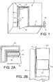
- FIG. 1 we can see a first embodiment of a detection device according to the present invention for detecting the opening and closing of a door 2.
- the detection device comprises an electric circuit 4 adapted to be closed by closing the door 2 and opened by opening the door 2, the opening and closing of the circuit being processed by a treatment unit 5.
- information which, depending on the passage or not of the current, emits an information signal relating to the closing or opening of the door.
- the door 2 has a doorframe 6 defining an opening 8 and a door 10 intended to be pressed against the doorframe 6 to close the opening 8.
- the frame 6 comprises an outer frame 12 made of conductive material, an inner frame 14 also made of conductive material, the first 12 and the second frame 14 are electrically connected and connected to a source of electrical current 16, forming the circuit electric 4.
- the inner frame 14 has an electrical discontinuity. In the example shown, it comprises a first portion 14.1 and a second portion 14.2 separated by a space 15 filled either with air or with an electrically insulating solid material.
- the leaf 10 is pivotally mounted in the example shown on the frame 6, but it could also be slidably mounted therein.
- the leaf 10 comprises at least one element 18 made of electrically conductive material disposed in such a way that it makes the first 14.1 and second 14.2 parts of the inner frame 14 come into electrical contact when the leaf 10 is applied against the frame 6.
- the outer frame 12 and the inner frame 14 formed by profiles.
- the outer frame 12 has a cross-section in the form of a square and the inner frame has a rectangular cross section.
- An electrically insulating material 17 is interposed between the outer frame 12 and the inner frame 14.
- the element 18 is formed by a plate mounted on the face of the wing 10 intended to come into contact with the doorframe 6.
- the plate 18 does not electrically connect the first 14.1 and second 14.2 parts of the inner frame 14, the current does not flow in the electric circuit 4, the processing unit then detects the open position of the door 2.
- the present invention also applies to windows.
- windows In the case of multi-leaf windows, in particular with two leaves, it is planned to be able to detect the opening of one and / or the other of the leaves.
- the element carried by each of the leaves, and able to open the electrical circuit when the leaf is closed is arranged on the side of the window bearing the hinges. This element can also be arranged on one of the other parts of the frame of the window.
- the electrically conductive elements may be, for example made of solid conductive material or comprise a core or a layer of conductive material.
- a keeper with a moving part, this movable part closing the electric circuit when the door is open, and opening the circuit during closing of the door, by pressing the bolt on the mobile part of the latch .
- the closure of the electrical circuit is substantially at the level of a door handle (not shown), but the plate 18, as well as the discontinuity of the inner frame 14 may be provided at a different location, for example on an upper part of the door or the side of the hinges, so as to further improve the aesthetics of the door.
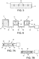
- FIG. 4A and 4B another embodiment of a detection device applied to a door can be seen, in this case opening or closing of the electric circuit is obtained by a movable conductive part in the doorframe, the displacement of which is controlled by the door knocking.
- the outer frame 12 which is discontinuous and has a first 12.1 and second 12.2 parts separated by a space 15 non-electrically conductive; the parts 12.1 and 12.2 are intended to be brought into electrical contact by filling the space 15 or crossing by an electrical conductor of the space 15.
- a conductive part 22 is movably mounted in the space 15. It may be for example T-shaped, the two branches of the T 22.1, 22.2 coming into contact respectively with the parts 12.1, 12.2 and allowing the passage of the current.
- the foot 22.3 of the T 22 is mounted in the space 15 and is intended to come into contact with the leaf 10.
- the T 22 is elastically urged towards the outside of the outer frame 12, in the direction of the leaf 10.
- the detection device may allow, for example to activate a lighting inside the room or space closed by the door.
- LED-type bulbs 24 connected in parallel to the inner frame 14 and the outer frame 12, as shown in FIG. figure 5 .
- the diodes illuminate the interior of the space.
- the detection device according to the present invention can be integrated into a piece of furniture made of electrically conductive material, for example aluminum to illuminate the interior of the furniture, when a user opens the door. By opening the leaf, the pressure on the moving part 22 is released, which then allows the current to flow in the inner 14 and outer 12 frames and in the diodes.
- Provision can be made to have a home surveillance installation comprising several devices according to the present invention, in which the detection devices can all be identical or be of different structures, for example a door or several doors can be equipped with the device. according to the second embodiment and the windows may be equipped with the device according to the first embodiment.
- FIG. 7A and 7B another embodiment of a detection device which does not form part of the present invention can be seen, particularly adapted to windows in the roofs, of the Velux® type.
- This type of window is equipped with an opening rotatably mounted about an axis passing substantially at its middle portion.
- the opening of this type of window is made by pulling on a handle disposed along an amount of the opening, the movement of this handle causes the bolt to move relative to the striker, and the unlocking of the opening relative to the frame.
- This type of window can be difficult to manipulate, especially in the case of large windows. Indeed, because of the weight of the opening, it can be difficult to retain a person and it may be driven by the movement of the opening. In addition, closing this type of window requires raising the door, which can also be problematic.
- the Velux® it was envisaged to assist the opening and closing of the Velux® by an electric motor, which when handling the handle starts to help the rotation in a direction of opening or closing from the window.
- the motor can then exert a torque on the opening at its axis, or exert a pulling force or thrust on the opening by a screw rack system mounted at one end of the opening.
- a displacement detection device attached to the opening detects the movement of the handle relative to the opening.
- This detection device is directly integrated in the handle and does not require an external detection device.
- FIG. 7A and 7B we can see an embodiment of such a handle 40 having a first portion 42 and a second portion 44 substantially parallel and movable relative to each other.
- the first part 42 is fixed to the frame of the opening (not shown), and the second part 44 is hinged, for example on the first part or on the frame of the window.
- Each portion 42, 44 is of elongated shape, and has a projection 46, 48 substantially in its central part, facing the projection 48, 46 of the other portion 44, 42.
- the two parts 42, 44 are connected to a processing unit 5.
- the handle portions 42, 44 are elastically spaced from each other by resilient means 50. Thus without effort countering the forces exerted by the elastic means, the parts are remote and the electrical circuit is open.
- Figure 7B which causes the closing of the electrical circuit and the passage of the current, which is detected by the processing unit 5.
- the processing unit 5 considers the closing of the circuit as a desire to open the window and sends a suitable signal to the electric motor or a power source of the engine.
- the actuation of the handle is detected without the use of an external detection device, the handle itself is part of the detection device.
- the system is then simplified and more aesthetic.
- the detection device can also be applied to the large door opening, the manual movement of which can be difficult or the opening of the lid or trunk of a motor vehicle.
- the shape of the two parts 42, 44 is not limited to the form described, it can be provided for example projections at each end of the elongate body.
- the handles in the case of the Velux, are covered with an electrically insulating coating, such as a paint.
- the circuit operates at low voltage. Thus, the users are not likely to be electrocuted.
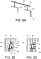
- FIG. 8A to 8C a schematic representation of a first example of a third embodiment of a displacement detection device which is not part of the present invention applied to the monitoring of objects, in particular tables, can be seen.
- a table can be fixed by a rod to a cable stretched along a wall. This cable can go around the room and support several paintings.
- the detection device which does not form part of the invention comprises two parallel electrical conductors 52, 54 intended to support at least one panel 56, these electrical conductors 52, 54, for example of the cable type, form part of an electrical circuit and are connected to a processing unit (not shown).
- the board 56 is hooked to the cables 52, 54 via a rod 58 fixed by a first end 60 to the board 56 and a second end 62 to the cables 52, 54.
- the second end 62 is hook-shaped.
- the detection device which does not form part of the present invention also comprises a contactor 64 interposed between the rod 58 and the cables 52, 54, which contactor 64 is movable relative to the electrical conductors 52, 54.
- the contactor 64 comprises a body 65 provided on one side with two grooves 66, 68 each receiving a cable 52, 54, a pin 70 movable in the body 65 and a metallic conductor element 72 for electrically connecting the two cables 52, 54.
- the conductive element 72 is held in contact with the stud 70 by a spring 74.
- the processing unit then sends a signal of absence of the table.
- All the boards attached to the cables 52, 54 may be equipped with such a detection device.
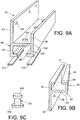
- FIG. 9A to 9C and 10A to 10C a second exemplary embodiment of the third embodiment of a detection device which does not form part of the present invention, in which the cables 52, 54 are replaced by a cornice formed of two sections made of electrically conductive materials, can be seen electrically insulated.
- the detection device which is not part of the present invention comprises a support 76 for hanging a table 56 forming a cornice along a wall 78.
- Said support is formed by a lower element 80 and an upper element 82, of superimposed metal profile type, intended to be fixed to the wall 78.
- the lower element 80 comprises a tube 84 of axis X1 with a rectangular section having an axial groove 86 in a side 90 of the tube 84.
- a side 92 orthogonal to the side 90 having the groove 86, is extended by a support plate 94, so as to form a base intended to come into plane contact with the wall 78.
- the upper element 82 has substantially the same shape as that of the lower element 80.
- the references used to designate the parts of the element 80 will be used by adding "'", to designate the similar parts of the upper element 82.
- the upper element 82 is disposed on the lower element 80, so that the groove 86 'is opposite the groove 86.
- the upper element comprises parallel to the support plate 94 ', a plate 96' extending from one side 100 'parallel to the side 92'.
- Orifices 102 ' are formed in a side 104' opposite the side 90 'having the groove 86', to allow passage of a finger 200.
- the plates 94, 94 ' comprise orifices 106, 106' for fastening the upper elements 82 and lower 80 to the wall 78.
- a plunger 202 is movably mounted in the tube 84, orthogonal to its axis, and protrudes into the tube 84 'through the grooves 86, 86'.
- the plunger 202 capable of conducting the electric current, comprises at a lower end a base 204 disposed in the tube 84 and at an upper end a feeler 206 in the tube 84 ', facing an orifice 102', the probe 206 being intended to come into contact with the finger 200.
- the plunger 202 is resiliently returned towards the orifice 102 'by an elastic means 208, helical spring type mounted in reaction between a bottom of a bore formed in the base 204 of the plunger 202 and the side 104.
- the finger 200 forms the end of the suspension rod of the board.
- Two strips 210 of electrically insulating material are arranged along the grooves 86, 86 'so as to isolate the two upper elements 82 and lower 80.
- the two sections 80, 82 and the plunger 202 are part of an electrical circuit powered by a processing unit (not shown).
- the profiles 80, 82 are intended to run along a wall or several walls of a room to support several tables. It is then provided, in the upper profile 82, orifices where you want to hang the tables.
- the presence detection devices of the arrays are electrically connected in series. Thus, in the absence of a table the processing unit will send an alarm signal, while this absence may be due to a desire not to hang an array at this location. It is then advantageously provided a device for exerting a force on the plunger so as to keep it in the low position, an exemplary embodiment of which is shown in FIG. Figure 10C .
- a body 212 provided with a protruding nipple 214 of similar shape and size as the finger 200 of the suspension rod and a pin 216 for enter a bore 218 provided in the body 212 and a passage 220 formed in the plate 96 '.
- the pin 214 is then held pressed against the probe 206 by mounting the pin 216 in the bore 218 and the passage 220.
- This device thus forms a decoy for the detection device.
- the rod 58 is integral with the board 56.
- the devices embodying the present invention operate advantageously at low voltage, for example less than 5V and a current intensity of between 1 ⁇ A and a few amperes.
Landscapes
- Engineering & Computer Science (AREA)
- Computer Security & Cryptography (AREA)
- Physics & Mathematics (AREA)
- General Physics & Mathematics (AREA)
- Burglar Alarm Systems (AREA)
- Geophysics And Detection Of Objects (AREA)
- Power-Operated Mechanisms For Wings (AREA)
- Measurement Of Length, Angles, Or The Like Using Electric Or Magnetic Means (AREA)
Priority Applications (1)
| Application Number | Priority Date | Filing Date | Title |
|---|---|---|---|
| PL07301443T PL1914770T3 (pl) | 2006-10-19 | 2007-10-09 | Urządzenie do wykrywania pozycji względnej dwóch elementów o polepszonym połączeniu |
Applications Claiming Priority (1)
| Application Number | Priority Date | Filing Date | Title |
|---|---|---|---|
| FR0654361A FR2907595B1 (fr) | 2006-10-19 | 2006-10-19 | Dispositif de detection de la position relative de deux elements a integration amelioree |
Publications (3)
| Publication Number | Publication Date |
|---|---|
| EP1914770A2 EP1914770A2 (fr) | 2008-04-23 |
| EP1914770A3 EP1914770A3 (fr) | 2014-05-14 |
| EP1914770B1 true EP1914770B1 (fr) | 2017-08-09 |
Family
ID=38038432
Family Applications (1)
| Application Number | Title | Priority Date | Filing Date |
|---|---|---|---|
| EP07301443.3A Active EP1914770B1 (fr) | 2006-10-19 | 2007-10-09 | Dispositif de détection de la position rélative de deux éléments à intégration améliorée |
Country Status (6)
| Country | Link |
|---|---|
| US (1) | US7916019B2 (pl) |
| EP (1) | EP1914770B1 (pl) |
| JP (1) | JP4929123B2 (pl) |
| ES (1) | ES2643401T3 (pl) |
| FR (1) | FR2907595B1 (pl) |
| PL (1) | PL1914770T3 (pl) |
Cited By (1)
| Publication number | Priority date | Publication date | Assignee | Title |
|---|---|---|---|---|
| CN110295796A (zh) * | 2018-03-22 | 2019-10-01 | 中兴通讯股份有限公司 | 一种智能门锁告警方法及装置 |
Families Citing this family (4)
| Publication number | Priority date | Publication date | Assignee | Title |
|---|---|---|---|---|
| LU91996B1 (en) * | 2012-05-10 | 2013-11-11 | Iee Sarl | Seat configured for occupancy state detection |
| CN102887300B (zh) * | 2012-09-20 | 2015-02-11 | 深圳市华星光电技术有限公司 | 一种液晶玻璃基板存储架 |
| KR102003331B1 (ko) * | 2018-02-01 | 2019-07-24 | 허성범 | 도어락 및 이를 구비하는 도어 조립체 |
| US12416402B1 (en) * | 2024-10-17 | 2025-09-16 | Teliee Popov | Seamless light system for thresholds, cabinets, and baseboards |
Family Cites Families (46)
| Publication number | Priority date | Publication date | Assignee | Title |
|---|---|---|---|---|
| US1827366A (en) * | 1931-10-13 | Jamaica | ||
| DE219704C (pl) * | ||||
| US1738508A (en) * | 1928-02-10 | 1929-12-03 | Bonnell Morgan | Alarm switch mechanism |
| US2281193A (en) * | 1941-09-04 | 1942-04-28 | Hollingsworth Campbell | Burglar alarm |
| US2615083A (en) * | 1946-09-21 | 1952-10-21 | Krueger August | Burglar alarm system |
| US2592660A (en) * | 1949-08-19 | 1952-04-15 | Harold W Crumley | Plunger type cam actuated switch |
| US3051935A (en) * | 1959-05-21 | 1962-08-28 | Clarence P Willson | Protective screen |
| US3161742A (en) * | 1961-08-24 | 1964-12-15 | Specialties Dev Corp | Magnetic intruder and fire deterctor |
| US3147468A (en) * | 1962-07-24 | 1964-09-01 | Edward N Daniels | Alarm systems |
| US3263040A (en) * | 1964-06-29 | 1966-07-26 | Harry F Bliven | Pressure operated circuit controlling devices operable on relative movement between two elements |
| US3426166A (en) * | 1966-06-09 | 1969-02-04 | Int Standard Electric Corp | Magnetic closure and switch for doors and similar devices |
| US3653022A (en) * | 1969-05-09 | 1972-03-28 | Murry Tall | Burglar and fire alarm system |
| US3604984A (en) * | 1969-12-22 | 1971-09-14 | Asea Ab | Electrical connection system formed of plinths with opposed pairs of rolls in front and back for receiving connectors |
| GB1414982A (en) * | 1972-01-25 | 1975-11-26 | Granley Products London Ltd | Device responsive to the opening of a door |
| US3838234A (en) * | 1973-07-02 | 1974-09-24 | Hager & Sons Hinge Mfg | Hinge through which an electrical circuit is completed with means to interrupt the circuit |
| US3924256A (en) * | 1974-01-08 | 1975-12-02 | Morton H Cohen | Burglar alarm switch |
| US3968337A (en) * | 1974-07-26 | 1976-07-06 | Cole Donald G | Door-actuated alarm switch |
| US3967478A (en) * | 1975-06-09 | 1976-07-06 | Guinn Stanley G | Door latching apparatus actuated by cleansing agent sensor |
| US4030089A (en) * | 1976-04-02 | 1977-06-14 | Wolfgang Wurfel | Alarm system |
| CH625605A5 (pl) * | 1976-10-02 | 1981-09-30 | Sick Optik Elektronik Erwin | |
| US4415893A (en) * | 1978-06-27 | 1983-11-15 | All-Lock Electronics, Inc. | Door control system |
| US4178588A (en) * | 1978-07-05 | 1979-12-11 | James Queren | Burglar alarm system |
| US4516114A (en) * | 1983-03-07 | 1985-05-07 | Securitron-Magnalock Corp. | Magnetic locking status detection system |
| US4556765A (en) * | 1983-05-13 | 1985-12-03 | Pittway Corporation | Security interface system for a door, window or the like |
| US4679881A (en) * | 1985-05-07 | 1987-07-14 | American District Telegraph Company | Electrical interconnection apparatus and technique |
| US4814750A (en) * | 1987-11-20 | 1989-03-21 | Pace Window & Door Corp. | Window screen alarm |
| DE8911033U1 (de) * | 1989-09-14 | 1989-12-21 | Burczik, Werner, 4620 Castrop-Rauxel | Elektrisches Schaltelement, insbesondere zur Auslösung von Alarmanlagen |
| JPH0411177A (ja) * | 1990-01-17 | 1992-01-16 | Sekisui Chem Co Ltd | ドアの施錠検知装置 |
| JP2983239B2 (ja) * | 1990-02-15 | 1999-11-29 | 積水化学工業株式会社 | 施錠確認装置 |
| US5063372A (en) * | 1990-06-22 | 1991-11-05 | Ranco Incorporated Of Delaware | Door ajar alarm for refrigeration unit |
| US5406263A (en) * | 1992-07-27 | 1995-04-11 | Micron Communications, Inc. | Anti-theft method for detecting the unauthorized opening of containers and baggage |
| US5229560A (en) * | 1992-08-05 | 1993-07-20 | Demarco Stephen R | Vehicle door-jamb switch assembly |
| EP0582733A1 (en) * | 1992-08-11 | 1994-02-16 | LEDA Logarithmic Electrical Devices for Automation S.r.l. | A device for monitoring whether a door or window, for example of a building or vehicle, is open or closed |
| US5638049A (en) * | 1993-03-11 | 1997-06-10 | Arakawa & Co., Ltd. | Crime prevention display device, exhibit crime prevention alarm control method and apparatus therefor |
| US5673021A (en) * | 1996-05-22 | 1997-09-30 | Woods; Randall | Magnetic switch assembly for detecting unauthorized opening of doors or windows |
| IT1305878B1 (it) * | 1998-12-18 | 2001-05-21 | Motus S R L | Apparecchiatura antiintrusione per la protezione particolarmente diappartamenti e simili |
| DE69909740D1 (de) * | 1999-03-08 | 2003-08-28 | Hayde Georg | System zur verstellbaren Befestigung eines Gegenstandes an einer vertikalen Fläche |
| JP3458274B2 (ja) * | 2000-11-10 | 2003-10-20 | 共栄テクノス株式会社 | 家屋用防犯装置 |
| US6447139B1 (en) * | 2001-05-17 | 2002-09-10 | John M. Wilkes | Illuminated, decorative door guard system |
| US6784784B1 (en) * | 2001-06-22 | 2004-08-31 | Zehrung Raymond E | Request to exit switch for door alarm system |
| DE20220357U1 (de) * | 2002-03-08 | 2003-08-14 | Hörmann KG Antriebstechnik, 33803 Steinhagen | Vorrichtung zum Überwachen des Schliesszustandes eines Abschlusses |
| AUPS146502A0 (en) * | 2002-03-28 | 2002-05-09 | Traynor, Neil | Methods and apparatus relating to improved visual recognition and safety |
| US20050248466A1 (en) * | 2002-09-23 | 2005-11-10 | John Ghazarian | Safety door system |
| US7026897B2 (en) * | 2003-01-03 | 2006-04-11 | Honeywell International Inc. | Multiple output magnetic sensor |
| US6950033B1 (en) * | 2003-01-22 | 2005-09-27 | Louis N Guyre | Door bolt alarm |
| US7242297B2 (en) * | 2005-02-16 | 2007-07-10 | Vogt William R | Alarm sensor |
-
2006
- 2006-10-19 FR FR0654361A patent/FR2907595B1/fr not_active Expired - Fee Related
-
2007
- 2007-10-09 ES ES07301443.3T patent/ES2643401T3/es active Active
- 2007-10-09 EP EP07301443.3A patent/EP1914770B1/fr active Active
- 2007-10-09 PL PL07301443T patent/PL1914770T3/pl unknown
- 2007-10-18 US US11/874,403 patent/US7916019B2/en not_active Expired - Fee Related
- 2007-10-19 JP JP2007272432A patent/JP4929123B2/ja not_active Expired - Fee Related
Non-Patent Citations (1)
| Title |
|---|
| None * |
Cited By (1)
| Publication number | Priority date | Publication date | Assignee | Title |
|---|---|---|---|---|
| CN110295796A (zh) * | 2018-03-22 | 2019-10-01 | 中兴通讯股份有限公司 | 一种智能门锁告警方法及装置 |
Also Published As
| Publication number | Publication date |
|---|---|
| JP4929123B2 (ja) | 2012-05-09 |
| FR2907595A1 (fr) | 2008-04-25 |
| US7916019B2 (en) | 2011-03-29 |
| US20080094239A1 (en) | 2008-04-24 |
| EP1914770A3 (fr) | 2014-05-14 |
| EP1914770A2 (fr) | 2008-04-23 |
| FR2907595B1 (fr) | 2014-01-31 |
| ES2643401T3 (es) | 2017-11-22 |
| PL1914770T3 (pl) | 2018-04-30 |
| JP2008102937A (ja) | 2008-05-01 |
Similar Documents
| Publication | Publication Date | Title |
|---|---|---|
| FR2992114A1 (fr) | Dispositif motorise de manoeuvre destine a la manoeuvre d'un ecran mobile a toile enroulable d'un dispositif de couverture de fenetre ou d'ecran de projection. | |
| EP1914770A2 (fr) | Dispositif de détection de la position rélative de deux éléments à intégration améliorée | |
| EP2186452A1 (fr) | Actionneur de manoeuvre d'un rideau coulissant | |
| EP3408478B1 (fr) | Poignee affleurante avec fonction push-pull pour ouvrant de vehicule automobile | |
| EP1476628A1 (fr) | Systeme de fermeture de coffre motorisee pour vehicule automobile | |
| WO2015118241A1 (fr) | Appareillage électrique a encastrer | |
| WO2018046731A1 (fr) | Fenêtre coulissante pour un bâtiment et installation domotique comprenant une telle fenêtre coulissante | |
| EP3190253B1 (fr) | Fenêtre oscillo-battante pour un bâtiment et installation domotique comprenant une telle fenêtre oscillo-battante | |
| EP3168396B1 (fr) | Dispositif de verrouillage pour portail coulissant, et portail coulissant associé | |
| WO2020120398A1 (fr) | Poignée de porte a double système d'ouverture | |
| EP2071105A1 (fr) | Clé à insert escamotable | |
| FR2853682A1 (fr) | Dispositif d'actionnement pour un ouvrant | |
| EP3517721B1 (fr) | Fenêtre coulissante pour un bâtiment et installation domotique comprenant une telle fenêtre coulissante | |
| EP2459826A1 (fr) | Procédé d'assemblage d'une poignée dans un ouvrant de véhicule automobile et poignée d'ouvrant associée | |
| FR2942637A1 (fr) | Poignee d'un ouvrant de vehicule automobile | |
| BE1023588B1 (fr) | Porte formee d'un bati et d'un vantail dote d'un dispositif d'eclairage | |
| FR2748291A1 (fr) | Serrure carenee a plusieurs penes et mecanisme de surete loges dans un boitier unique | |
| EP4105417A1 (fr) | Dispositif de détection de l'état d'un système de fermeture d'une baie coulissante | |
| EP3709277A1 (fr) | Élément de système d'alarme | |
| FR3102786A1 (fr) | Dispositif de détection pour vantail | |
| EP1685996B1 (fr) | Véhicule automobile possedant une face d'un ouvrant recouverte d'une feuille sensible à la pression | |
| EP1820925A1 (fr) | Dispositif d'actionnement pour un ouvrant de vehicule automobile | |
| FR3099512A1 (fr) | Dispositif d’entraînement motorisé d’un volet battant, volet battant et installation pour un bâtiment associés | |
| FR2866980A1 (fr) | Dispositif electrique de securite d'une serrure de porte, notamment de porte d'ascenseur | |
| FR2786526A1 (fr) | Dispositif de verrouillage en rotation d'une penture de volet |
Legal Events
| Date | Code | Title | Description |
|---|---|---|---|
| PUAI | Public reference made under article 153(3) epc to a published international application that has entered the european phase |
Free format text: ORIGINAL CODE: 0009012 |
|
| AK | Designated contracting states |
Kind code of ref document: A2 Designated state(s): AT BE BG CH CY CZ DE DK EE ES FI FR GB GR HU IE IS IT LI LT LU LV MC MT NL PL PT RO SE SI SK TR |
|
| AX | Request for extension of the european patent |
Extension state: AL BA HR MK RS |
|
| PUAL | Search report despatched |
Free format text: ORIGINAL CODE: 0009013 |
|
| AK | Designated contracting states |
Kind code of ref document: A3 Designated state(s): AT BE BG CH CY CZ DE DK EE ES FI FR GB GR HU IE IS IT LI LT LU LV MC MT NL PL PT RO SE SI SK TR |
|
| AX | Request for extension of the european patent |
Extension state: AL BA HR MK RS |
|
| RIC1 | Information provided on ipc code assigned before grant |
Ipc: H01H 3/16 20060101AFI20140404BHEP Ipc: H01H 3/14 20060101ALN20140404BHEP Ipc: G08B 13/08 20060101ALI20140404BHEP |
|
| 17P | Request for examination filed |
Effective date: 20141112 |
|
| RBV | Designated contracting states (corrected) |
Designated state(s): AT BE BG CH CY CZ DE DK EE ES FI FR GB GR HU IE IS IT LI LT LU LV MC MT NL PL PT RO SE SI SK TR |
|
| RBV | Designated contracting states (corrected) |
Designated state(s): AT BE BG CH CY CZ DE DK EE ES FI FR GB GR HU IE IS IT LI LT LU LV MC MT NL PL PT RO SE SI SK TR |
|
| RBV | Designated contracting states (corrected) |
Designated state(s): AT BE BG CH CY CZ DE DK EE ES FI FR GB GR HU IE IS IT LI LT LU LV MC MT NL PL PT RO SE SI SK TR |
|
| AKX | Designation fees paid |
Designated state(s): AT BE BG CH CY CZ DE DK EE ES FI FR GB GR HU IE IS IT LI LT LU LV MC MT NL PL PT RO SE SI SK TR |
|
| AXX | Extension fees paid |
Extension state: MK Extension state: RS Extension state: HR Extension state: AL Extension state: BA |
|
| 17Q | First examination report despatched |
Effective date: 20160719 |
|
| GRAP | Despatch of communication of intention to grant a patent |
Free format text: ORIGINAL CODE: EPIDOSNIGR1 |
|
| RIC1 | Information provided on ipc code assigned before grant |
Ipc: H01H 3/14 20060101ALN20170315BHEP Ipc: G08B 13/08 20060101ALI20170315BHEP Ipc: H01H 3/16 20060101AFI20170315BHEP |
|
| RIC1 | Information provided on ipc code assigned before grant |
Ipc: H01H 3/16 20060101AFI20170320BHEP Ipc: G08B 13/08 20060101ALI20170320BHEP Ipc: H01H 3/14 20060101ALN20170320BHEP |
|
| INTG | Intention to grant announced |
Effective date: 20170405 |
|
| GRAS | Grant fee paid |
Free format text: ORIGINAL CODE: EPIDOSNIGR3 |
|
| GRAA | (expected) grant |
Free format text: ORIGINAL CODE: 0009210 |
|
| AK | Designated contracting states |
Kind code of ref document: B1 Designated state(s): AT BE BG CH CY CZ DE DK EE ES FI FR GB GR HU IE IS IT LI LT LU LV MC MT NL PL PT RO SE SI SK TR |
|
| REG | Reference to a national code |
Ref country code: GB Ref legal event code: FG4D Free format text: NOT ENGLISH |
|
| REG | Reference to a national code |
Ref country code: CH Ref legal event code: EP Ref country code: AT Ref legal event code: REF Ref document number: 917655 Country of ref document: AT Kind code of ref document: T Effective date: 20170815 |
|
| REG | Reference to a national code |
Ref country code: IE Ref legal event code: FG4D Free format text: LANGUAGE OF EP DOCUMENT: FRENCH |
|
| REG | Reference to a national code |
Ref country code: DE Ref legal event code: R096 Ref document number: 602007051906 Country of ref document: DE |
|
| REG | Reference to a national code |
Ref country code: DE Ref legal event code: R081 Ref document number: 602007051906 Country of ref document: DE Owner name: BUBENDORFF SOCIETE ANONYME, FR Free format text: FORMER OWNERS: BUBENDORFF SOCIETE ANONYME, ATTENSCHWILLER, FR; COMMISSARIAT A L'ENERGIE ATOMIQUE, PARIS, FR |
|
| REG | Reference to a national code |
Ref country code: FR Ref legal event code: PLFP Year of fee payment: 11 |
|
| REG | Reference to a national code |
Ref country code: ES Ref legal event code: PC2A Owner name: BUBENDORFF SOCIETE ANONYME Effective date: 20171110 |
|
| REG | Reference to a national code |
Ref country code: ES Ref legal event code: FG2A Ref document number: 2643401 Country of ref document: ES Kind code of ref document: T3 Effective date: 20171122 |
|
| REG | Reference to a national code |
Ref country code: NL Ref legal event code: MP Effective date: 20170809 |
|
| REG | Reference to a national code |
Ref country code: LT Ref legal event code: MG4D |
|
| REG | Reference to a national code |
Ref country code: AT Ref legal event code: MK05 Ref document number: 917655 Country of ref document: AT Kind code of ref document: T Effective date: 20170809 |
|
| PG25 | Lapsed in a contracting state [announced via postgrant information from national office to epo] |
Ref country code: LT Free format text: LAPSE BECAUSE OF FAILURE TO SUBMIT A TRANSLATION OF THE DESCRIPTION OR TO PAY THE FEE WITHIN THE PRESCRIBED TIME-LIMIT Effective date: 20170809 Ref country code: FI Free format text: LAPSE BECAUSE OF FAILURE TO SUBMIT A TRANSLATION OF THE DESCRIPTION OR TO PAY THE FEE WITHIN THE PRESCRIBED TIME-LIMIT Effective date: 20170809 Ref country code: NL Free format text: LAPSE BECAUSE OF FAILURE TO SUBMIT A TRANSLATION OF THE DESCRIPTION OR TO PAY THE FEE WITHIN THE PRESCRIBED TIME-LIMIT Effective date: 20170809 Ref country code: SE Free format text: LAPSE BECAUSE OF FAILURE TO SUBMIT A TRANSLATION OF THE DESCRIPTION OR TO PAY THE FEE WITHIN THE PRESCRIBED TIME-LIMIT Effective date: 20170809 Ref country code: AT Free format text: LAPSE BECAUSE OF FAILURE TO SUBMIT A TRANSLATION OF THE DESCRIPTION OR TO PAY THE FEE WITHIN THE PRESCRIBED TIME-LIMIT Effective date: 20170809 |
|
| PG25 | Lapsed in a contracting state [announced via postgrant information from national office to epo] |
Ref country code: BG Free format text: LAPSE BECAUSE OF FAILURE TO SUBMIT A TRANSLATION OF THE DESCRIPTION OR TO PAY THE FEE WITHIN THE PRESCRIBED TIME-LIMIT Effective date: 20171109 Ref country code: IS Free format text: LAPSE BECAUSE OF FAILURE TO SUBMIT A TRANSLATION OF THE DESCRIPTION OR TO PAY THE FEE WITHIN THE PRESCRIBED TIME-LIMIT Effective date: 20171209 Ref country code: LV Free format text: LAPSE BECAUSE OF FAILURE TO SUBMIT A TRANSLATION OF THE DESCRIPTION OR TO PAY THE FEE WITHIN THE PRESCRIBED TIME-LIMIT Effective date: 20170809 Ref country code: GR Free format text: LAPSE BECAUSE OF FAILURE TO SUBMIT A TRANSLATION OF THE DESCRIPTION OR TO PAY THE FEE WITHIN THE PRESCRIBED TIME-LIMIT Effective date: 20171110 |
|
| PG25 | Lapsed in a contracting state [announced via postgrant information from national office to epo] |
Ref country code: CZ Free format text: LAPSE BECAUSE OF FAILURE TO SUBMIT A TRANSLATION OF THE DESCRIPTION OR TO PAY THE FEE WITHIN THE PRESCRIBED TIME-LIMIT Effective date: 20170809 Ref country code: RO Free format text: LAPSE BECAUSE OF FAILURE TO SUBMIT A TRANSLATION OF THE DESCRIPTION OR TO PAY THE FEE WITHIN THE PRESCRIBED TIME-LIMIT Effective date: 20170809 Ref country code: DK Free format text: LAPSE BECAUSE OF FAILURE TO SUBMIT A TRANSLATION OF THE DESCRIPTION OR TO PAY THE FEE WITHIN THE PRESCRIBED TIME-LIMIT Effective date: 20170809 |
|
| REG | Reference to a national code |
Ref country code: DE Ref legal event code: R097 Ref document number: 602007051906 Country of ref document: DE |
|
| PG25 | Lapsed in a contracting state [announced via postgrant information from national office to epo] |
Ref country code: SK Free format text: LAPSE BECAUSE OF FAILURE TO SUBMIT A TRANSLATION OF THE DESCRIPTION OR TO PAY THE FEE WITHIN THE PRESCRIBED TIME-LIMIT Effective date: 20170809 Ref country code: MC Free format text: LAPSE BECAUSE OF FAILURE TO SUBMIT A TRANSLATION OF THE DESCRIPTION OR TO PAY THE FEE WITHIN THE PRESCRIBED TIME-LIMIT Effective date: 20170809 Ref country code: EE Free format text: LAPSE BECAUSE OF FAILURE TO SUBMIT A TRANSLATION OF THE DESCRIPTION OR TO PAY THE FEE WITHIN THE PRESCRIBED TIME-LIMIT Effective date: 20170809 |
|
| REG | Reference to a national code |
Ref country code: CH Ref legal event code: PL |
|
| PLBE | No opposition filed within time limit |
Free format text: ORIGINAL CODE: 0009261 |
|
| STAA | Information on the status of an ep patent application or granted ep patent |
Free format text: STATUS: NO OPPOSITION FILED WITHIN TIME LIMIT |
|
| 26N | No opposition filed |
Effective date: 20180511 |
|
| GBPC | Gb: european patent ceased through non-payment of renewal fee |
Effective date: 20171109 |
|
| REG | Reference to a national code |
Ref country code: IE Ref legal event code: MM4A |
|
| PG25 | Lapsed in a contracting state [announced via postgrant information from national office to epo] |
Ref country code: LU Free format text: LAPSE BECAUSE OF NON-PAYMENT OF DUE FEES Effective date: 20171009 Ref country code: LI Free format text: LAPSE BECAUSE OF NON-PAYMENT OF DUE FEES Effective date: 20171031 Ref country code: CH Free format text: LAPSE BECAUSE OF NON-PAYMENT OF DUE FEES Effective date: 20171031 |
|
| REG | Reference to a national code |
Ref country code: BE Ref legal event code: MM Effective date: 20171031 |
|
| PG25 | Lapsed in a contracting state [announced via postgrant information from national office to epo] |
Ref country code: BE Free format text: LAPSE BECAUSE OF NON-PAYMENT OF DUE FEES Effective date: 20171031 Ref country code: SI Free format text: LAPSE BECAUSE OF FAILURE TO SUBMIT A TRANSLATION OF THE DESCRIPTION OR TO PAY THE FEE WITHIN THE PRESCRIBED TIME-LIMIT Effective date: 20170809 |
|
| PG25 | Lapsed in a contracting state [announced via postgrant information from national office to epo] |
Ref country code: MT Free format text: LAPSE BECAUSE OF FAILURE TO SUBMIT A TRANSLATION OF THE DESCRIPTION OR TO PAY THE FEE WITHIN THE PRESCRIBED TIME-LIMIT Effective date: 20170809 |
|
| REG | Reference to a national code |
Ref country code: FR Ref legal event code: PLFP Year of fee payment: 12 |
|
| PG25 | Lapsed in a contracting state [announced via postgrant information from national office to epo] |
Ref country code: IE Free format text: LAPSE BECAUSE OF NON-PAYMENT OF DUE FEES Effective date: 20171009 |
|
| PG25 | Lapsed in a contracting state [announced via postgrant information from national office to epo] |
Ref country code: GB Free format text: LAPSE BECAUSE OF NON-PAYMENT OF DUE FEES Effective date: 20171109 |
|
| PG25 | Lapsed in a contracting state [announced via postgrant information from national office to epo] |
Ref country code: HU Free format text: LAPSE BECAUSE OF FAILURE TO SUBMIT A TRANSLATION OF THE DESCRIPTION OR TO PAY THE FEE WITHIN THE PRESCRIBED TIME-LIMIT; INVALID AB INITIO Effective date: 20071009 |
|
| PG25 | Lapsed in a contracting state [announced via postgrant information from national office to epo] |
Ref country code: CY Free format text: LAPSE BECAUSE OF NON-PAYMENT OF DUE FEES Effective date: 20170809 |
|
| PG25 | Lapsed in a contracting state [announced via postgrant information from national office to epo] |
Ref country code: TR Free format text: LAPSE BECAUSE OF FAILURE TO SUBMIT A TRANSLATION OF THE DESCRIPTION OR TO PAY THE FEE WITHIN THE PRESCRIBED TIME-LIMIT Effective date: 20170809 |
|
| PG25 | Lapsed in a contracting state [announced via postgrant information from national office to epo] |
Ref country code: PT Free format text: LAPSE BECAUSE OF FAILURE TO SUBMIT A TRANSLATION OF THE DESCRIPTION OR TO PAY THE FEE WITHIN THE PRESCRIBED TIME-LIMIT Effective date: 20170809 |
|
| PGFP | Annual fee paid to national office [announced via postgrant information from national office to epo] |
Ref country code: PL Payment date: 20240926 Year of fee payment: 18 |
|
| PGFP | Annual fee paid to national office [announced via postgrant information from national office to epo] |
Ref country code: DE Payment date: 20241105 Year of fee payment: 18 |
|
| PGFP | Annual fee paid to national office [announced via postgrant information from national office to epo] |
Ref country code: IT Payment date: 20241028 Year of fee payment: 18 Ref country code: ES Payment date: 20241210 Year of fee payment: 18 |
|
| PGFP | Annual fee paid to national office [announced via postgrant information from national office to epo] |
Ref country code: FR Payment date: 20250922 Year of fee payment: 19 |
|
| REG | Reference to a national code |
Ref country code: DE Ref legal event code: R119 Ref document number: 602007051906 Country of ref document: DE |
|
| PG25 | Lapsed in a contracting state [announced via postgrant information from national office to epo] |
Ref country code: DE Free format text: LAPSE BECAUSE OF NON-PAYMENT OF DUE FEES Effective date: 20260501 |