EP1914764A1 - Lithium-ion Capacitor - Google Patents
Lithium-ion Capacitor Download PDFInfo
- Publication number
- EP1914764A1 EP1914764A1 EP07118716A EP07118716A EP1914764A1 EP 1914764 A1 EP1914764 A1 EP 1914764A1 EP 07118716 A EP07118716 A EP 07118716A EP 07118716 A EP07118716 A EP 07118716A EP 1914764 A1 EP1914764 A1 EP 1914764A1
- Authority
- EP
- European Patent Office
- Prior art keywords
- lithium
- negative electrode
- positive electrode
- active material
- ion capacitor
- Prior art date
- Legal status (The legal status is an assumption and is not a legal conclusion. Google has not performed a legal analysis and makes no representation as to the accuracy of the status listed.)
- Granted
Links
- 229910001416 lithium ion Inorganic materials 0.000 title claims abstract description 126
- HBBGRARXTFLTSG-UHFFFAOYSA-N Lithium ion Chemical compound [Li+] HBBGRARXTFLTSG-UHFFFAOYSA-N 0.000 title claims abstract description 113
- 239000003990 capacitor Substances 0.000 title claims abstract description 75
- OKTJSMMVPCPJKN-UHFFFAOYSA-N Carbon Chemical compound [C] OKTJSMMVPCPJKN-UHFFFAOYSA-N 0.000 claims abstract description 64
- 239000007773 negative electrode material Substances 0.000 claims abstract description 54
- 229910002804 graphite Inorganic materials 0.000 claims abstract description 40
- 239000010439 graphite Substances 0.000 claims abstract description 40
- 239000007774 positive electrode material Substances 0.000 claims description 25
- 239000003792 electrolyte Substances 0.000 claims description 19
- 239000003960 organic solvent Substances 0.000 claims description 7
- 150000001450 anions Chemical class 0.000 claims description 5
- 238000002441 X-ray diffraction Methods 0.000 claims description 2
- 229910003002 lithium salt Inorganic materials 0.000 claims description 2
- 159000000002 lithium salts Chemical class 0.000 claims description 2
- 239000011149 active material Substances 0.000 abstract description 2
- 238000007599 discharging Methods 0.000 description 36
- WHXSMMKQMYFTQS-UHFFFAOYSA-N Lithium Chemical compound [Li] WHXSMMKQMYFTQS-UHFFFAOYSA-N 0.000 description 35
- 229910052744 lithium Inorganic materials 0.000 description 35
- 239000002245 particle Substances 0.000 description 29
- 229910052751 metal Inorganic materials 0.000 description 23
- 239000002184 metal Substances 0.000 description 23
- 238000007600 charging Methods 0.000 description 20
- 239000002002 slurry Substances 0.000 description 17
- 230000000052 comparative effect Effects 0.000 description 14
- 239000004020 conductor Substances 0.000 description 13
- 239000011230 binding agent Substances 0.000 description 12
- 238000000034 method Methods 0.000 description 10
- -1 polytetrafluoroethylene Polymers 0.000 description 10
- 238000003475 lamination Methods 0.000 description 9
- 239000000463 material Substances 0.000 description 9
- 239000000843 powder Substances 0.000 description 9
- 238000009826 distribution Methods 0.000 description 8
- 239000011248 coating agent Substances 0.000 description 6
- 238000000576 coating method Methods 0.000 description 6
- 230000005611 electricity Effects 0.000 description 6
- 238000005516 engineering process Methods 0.000 description 6
- XLYOFNOQVPJJNP-UHFFFAOYSA-N water Substances O XLYOFNOQVPJJNP-UHFFFAOYSA-N 0.000 description 6
- 229920002134 Carboxymethyl cellulose Polymers 0.000 description 5
- 239000006230 acetylene black Substances 0.000 description 5
- 229910052799 carbon Inorganic materials 0.000 description 5
- 238000012360 testing method Methods 0.000 description 5
- RYGMFSIKBFXOCR-UHFFFAOYSA-N Copper Chemical compound [Cu] RYGMFSIKBFXOCR-UHFFFAOYSA-N 0.000 description 4
- 229910001290 LiPF6 Inorganic materials 0.000 description 4
- 239000004698 Polyethylene Substances 0.000 description 4
- 229910052782 aluminium Inorganic materials 0.000 description 4
- XAGFODPZIPBFFR-UHFFFAOYSA-N aluminium Chemical compound [Al] XAGFODPZIPBFFR-UHFFFAOYSA-N 0.000 description 4
- 229910052802 copper Inorganic materials 0.000 description 4
- 239000010949 copper Substances 0.000 description 4
- 239000005001 laminate film Substances 0.000 description 4
- 238000004519 manufacturing process Methods 0.000 description 4
- 229920000573 polyethylene Polymers 0.000 description 4
- 238000003860 storage Methods 0.000 description 4
- 229920003048 styrene butadiene rubber Polymers 0.000 description 4
- WEVYAHXRMPXWCK-UHFFFAOYSA-N Acetonitrile Chemical compound CC#N WEVYAHXRMPXWCK-UHFFFAOYSA-N 0.000 description 3
- 239000004925 Acrylic resin Substances 0.000 description 3
- 229920000178 Acrylic resin Polymers 0.000 description 3
- YMWUJEATGCHHMB-UHFFFAOYSA-N Dichloromethane Chemical compound ClCCl YMWUJEATGCHHMB-UHFFFAOYSA-N 0.000 description 3
- OIFBSDVPJOWBCH-UHFFFAOYSA-N Diethyl carbonate Chemical compound CCOC(=O)OCC OIFBSDVPJOWBCH-UHFFFAOYSA-N 0.000 description 3
- KMTRUDSVKNLOMY-UHFFFAOYSA-N Ethylene carbonate Chemical compound O=C1OCCO1 KMTRUDSVKNLOMY-UHFFFAOYSA-N 0.000 description 3
- 239000001768 carboxy methyl cellulose Substances 0.000 description 3
- 235000010948 carboxy methyl cellulose Nutrition 0.000 description 3
- 239000008112 carboxymethyl-cellulose Substances 0.000 description 3
- 238000010281 constant-current constant-voltage charging Methods 0.000 description 3
- 238000011161 development Methods 0.000 description 3
- 239000007770 graphite material Substances 0.000 description 3
- 238000005259 measurement Methods 0.000 description 3
- 239000010935 stainless steel Substances 0.000 description 3
- 229910001220 stainless steel Inorganic materials 0.000 description 3
- 239000000758 substrate Substances 0.000 description 3
- YEJRWHAVMIAJKC-UHFFFAOYSA-N 4-Butyrolactone Chemical compound O=C1CCCO1 YEJRWHAVMIAJKC-UHFFFAOYSA-N 0.000 description 2
- 229920003026 Acene Polymers 0.000 description 2
- YCKRFDGAMUMZLT-UHFFFAOYSA-N Fluorine atom Chemical compound [F] YCKRFDGAMUMZLT-UHFFFAOYSA-N 0.000 description 2
- PXHVJJICTQNCMI-UHFFFAOYSA-N Nickel Chemical compound [Ni] PXHVJJICTQNCMI-UHFFFAOYSA-N 0.000 description 2
- 239000002033 PVDF binder Substances 0.000 description 2
- 239000004743 Polypropylene Substances 0.000 description 2
- 239000002174 Styrene-butadiene Substances 0.000 description 2
- 238000010276 construction Methods 0.000 description 2
- 238000000354 decomposition reaction Methods 0.000 description 2
- 238000010586 diagram Methods 0.000 description 2
- 230000000694 effects Effects 0.000 description 2
- 229920001971 elastomer Polymers 0.000 description 2
- 229910052731 fluorine Inorganic materials 0.000 description 2
- 239000011737 fluorine Substances 0.000 description 2
- 150000002500 ions Chemical group 0.000 description 2
- 230000002427 irreversible effect Effects 0.000 description 2
- 230000014759 maintenance of location Effects 0.000 description 2
- 239000012046 mixed solvent Substances 0.000 description 2
- 239000000203 mixture Substances 0.000 description 2
- 239000004745 nonwoven fabric Substances 0.000 description 2
- 229920001155 polypropylene Polymers 0.000 description 2
- 229920001343 polytetrafluoroethylene Polymers 0.000 description 2
- 239000004810 polytetrafluoroethylene Substances 0.000 description 2
- 229920002981 polyvinylidene fluoride Polymers 0.000 description 2
- RUOJZAUFBMNUDX-UHFFFAOYSA-N propylene carbonate Chemical compound CC1COC(=O)O1 RUOJZAUFBMNUDX-UHFFFAOYSA-N 0.000 description 2
- 239000011347 resin Substances 0.000 description 2
- 229920005989 resin Polymers 0.000 description 2
- 239000005060 rubber Substances 0.000 description 2
- 239000000565 sealant Substances 0.000 description 2
- 239000011877 solvent mixture Substances 0.000 description 2
- 229920005992 thermoplastic resin Polymers 0.000 description 2
- 239000002562 thickening agent Substances 0.000 description 2
- WNXJIVFYUVYPPR-UHFFFAOYSA-N 1,3-dioxolane Chemical compound C1COCO1 WNXJIVFYUVYPPR-UHFFFAOYSA-N 0.000 description 1
- 229910000838 Al alloy Inorganic materials 0.000 description 1
- XTHFKEDIFFGKHM-UHFFFAOYSA-N Dimethoxyethane Chemical compound COCCOC XTHFKEDIFFGKHM-UHFFFAOYSA-N 0.000 description 1
- JFBZPFYRPYOZCQ-UHFFFAOYSA-N [Li].[Al] Chemical compound [Li].[Al] JFBZPFYRPYOZCQ-UHFFFAOYSA-N 0.000 description 1
- 238000004458 analytical method Methods 0.000 description 1
- 230000015572 biosynthetic process Effects 0.000 description 1
- 239000003575 carbonaceous material Substances 0.000 description 1
- 238000006243 chemical reaction Methods 0.000 description 1
- 229920001940 conductive polymer Polymers 0.000 description 1
- 230000006866 deterioration Effects 0.000 description 1
- IEJIGPNLZYLLBP-UHFFFAOYSA-N dimethyl carbonate Chemical compound COC(=O)OC IEJIGPNLZYLLBP-UHFFFAOYSA-N 0.000 description 1
- 239000007772 electrode material Substances 0.000 description 1
- 230000007613 environmental effect Effects 0.000 description 1
- 238000011156 evaluation Methods 0.000 description 1
- 239000011888 foil Substances 0.000 description 1
- 239000007789 gas Substances 0.000 description 1
- 229910021385 hard carbon Inorganic materials 0.000 description 1
- 238000010438 heat treatment Methods 0.000 description 1
- 229910001540 lithium hexafluoroarsenate(V) Inorganic materials 0.000 description 1
- MHCFAGZWMAWTNR-UHFFFAOYSA-M lithium perchlorate Chemical compound [Li+].[O-]Cl(=O)(=O)=O MHCFAGZWMAWTNR-UHFFFAOYSA-M 0.000 description 1
- 229910001486 lithium perchlorate Inorganic materials 0.000 description 1
- 229910001496 lithium tetrafluoroborate Inorganic materials 0.000 description 1
- ACFSQHQYDZIPRL-UHFFFAOYSA-N lithium;bis(1,1,2,2,2-pentafluoroethylsulfonyl)azanide Chemical compound [Li+].FC(F)(F)C(F)(F)S(=O)(=O)[N-]S(=O)(=O)C(F)(F)C(F)(F)F ACFSQHQYDZIPRL-UHFFFAOYSA-N 0.000 description 1
- QSZMZKBZAYQGRS-UHFFFAOYSA-N lithium;bis(trifluoromethylsulfonyl)azanide Chemical compound [Li+].FC(F)(F)S(=O)(=O)[N-]S(=O)(=O)C(F)(F)F QSZMZKBZAYQGRS-UHFFFAOYSA-N 0.000 description 1
- 239000002931 mesocarbon microbead Substances 0.000 description 1
- 239000007769 metal material Substances 0.000 description 1
- 238000000465 moulding Methods 0.000 description 1
- 229910052759 nickel Inorganic materials 0.000 description 1
- 239000012299 nitrogen atmosphere Substances 0.000 description 1
- 230000002093 peripheral effect Effects 0.000 description 1
- 239000005011 phenolic resin Substances 0.000 description 1
- 239000011295 pitch Substances 0.000 description 1
- 239000011148 porous material Substances 0.000 description 1
- 238000000634 powder X-ray diffraction Methods 0.000 description 1
- 238000000790 scattering method Methods 0.000 description 1
- 238000007789 sealing Methods 0.000 description 1
- 239000002904 solvent Substances 0.000 description 1
- 235000015096 spirit Nutrition 0.000 description 1
- HXJUTPCZVOIRIF-UHFFFAOYSA-N sulfolane Chemical compound O=S1(=O)CCCC1 HXJUTPCZVOIRIF-UHFFFAOYSA-N 0.000 description 1
- 238000012546 transfer Methods 0.000 description 1
- 230000005612 types of electricity Effects 0.000 description 1
- 238000002525 ultrasonication Methods 0.000 description 1
Images


Classifications
-
- H—ELECTRICITY
- H01—ELECTRIC ELEMENTS
- H01G—CAPACITORS; CAPACITORS, RECTIFIERS, DETECTORS, SWITCHING DEVICES OR LIGHT-SENSITIVE DEVICES, OF THE ELECTROLYTIC TYPE
- H01G11/00—Hybrid capacitors, i.e. capacitors having different positive and negative electrodes; Electric double-layer [EDL] capacitors; Processes for the manufacture thereof or of parts thereof
- H01G11/22—Electrodes
- H01G11/30—Electrodes characterised by their material
- H01G11/32—Carbon-based
-
- H—ELECTRICITY
- H01—ELECTRIC ELEMENTS
- H01G—CAPACITORS; CAPACITORS, RECTIFIERS, DETECTORS, SWITCHING DEVICES OR LIGHT-SENSITIVE DEVICES, OF THE ELECTROLYTIC TYPE
- H01G4/00—Fixed capacitors; Processes of their manufacture
- H01G4/002—Details
- H01G4/005—Electrodes
- H01G4/008—Selection of materials
-
- H—ELECTRICITY
- H01—ELECTRIC ELEMENTS
- H01G—CAPACITORS; CAPACITORS, RECTIFIERS, DETECTORS, SWITCHING DEVICES OR LIGHT-SENSITIVE DEVICES, OF THE ELECTROLYTIC TYPE
- H01G11/00—Hybrid capacitors, i.e. capacitors having different positive and negative electrodes; Electric double-layer [EDL] capacitors; Processes for the manufacture thereof or of parts thereof
- H01G11/04—Hybrid capacitors
- H01G11/06—Hybrid capacitors with one of the electrodes allowing ions to be reversibly doped thereinto, e.g. lithium ion capacitors [LIC]
-
- H—ELECTRICITY
- H01—ELECTRIC ELEMENTS
- H01G—CAPACITORS; CAPACITORS, RECTIFIERS, DETECTORS, SWITCHING DEVICES OR LIGHT-SENSITIVE DEVICES, OF THE ELECTROLYTIC TYPE
- H01G11/00—Hybrid capacitors, i.e. capacitors having different positive and negative electrodes; Electric double-layer [EDL] capacitors; Processes for the manufacture thereof or of parts thereof
- H01G11/22—Electrodes
- H01G11/24—Electrodes characterised by structural features of the materials making up or comprised in the electrodes, e.g. form, surface area or porosity; characterised by the structural features of powders or particles used therefor
-
- H—ELECTRICITY
- H01—ELECTRIC ELEMENTS
- H01G—CAPACITORS; CAPACITORS, RECTIFIERS, DETECTORS, SWITCHING DEVICES OR LIGHT-SENSITIVE DEVICES, OF THE ELECTROLYTIC TYPE
- H01G11/00—Hybrid capacitors, i.e. capacitors having different positive and negative electrodes; Electric double-layer [EDL] capacitors; Processes for the manufacture thereof or of parts thereof
- H01G11/22—Electrodes
- H01G11/30—Electrodes characterised by their material
- H01G11/50—Electrodes characterised by their material specially adapted for lithium-ion capacitors, e.g. for lithium-doping or for intercalation
-
- Y—GENERAL TAGGING OF NEW TECHNOLOGICAL DEVELOPMENTS; GENERAL TAGGING OF CROSS-SECTIONAL TECHNOLOGIES SPANNING OVER SEVERAL SECTIONS OF THE IPC; TECHNICAL SUBJECTS COVERED BY FORMER USPC CROSS-REFERENCE ART COLLECTIONS [XRACs] AND DIGESTS
- Y02—TECHNOLOGIES OR APPLICATIONS FOR MITIGATION OR ADAPTATION AGAINST CLIMATE CHANGE
- Y02E—REDUCTION OF GREENHOUSE GAS [GHG] EMISSIONS, RELATED TO ENERGY GENERATION, TRANSMISSION OR DISTRIBUTION
- Y02E60/00—Enabling technologies; Technologies with a potential or indirect contribution to GHG emissions mitigation
- Y02E60/13—Energy storage using capacitors
-
- Y—GENERAL TAGGING OF NEW TECHNOLOGICAL DEVELOPMENTS; GENERAL TAGGING OF CROSS-SECTIONAL TECHNOLOGIES SPANNING OVER SEVERAL SECTIONS OF THE IPC; TECHNICAL SUBJECTS COVERED BY FORMER USPC CROSS-REFERENCE ART COLLECTIONS [XRACs] AND DIGESTS
- Y02—TECHNOLOGIES OR APPLICATIONS FOR MITIGATION OR ADAPTATION AGAINST CLIMATE CHANGE
- Y02T—CLIMATE CHANGE MITIGATION TECHNOLOGIES RELATED TO TRANSPORTATION
- Y02T10/00—Road transport of goods or passengers
- Y02T10/60—Other road transportation technologies with climate change mitigation effect
- Y02T10/70—Energy storage systems for electromobility, e.g. batteries
Definitions
- the present invention relates to a technology of a lithium-ion capacitor, and more particularly, to a technology which is well adaptable to a negative electrode material of a lithium-ion capacitor.
- JP-A-2005-203 130 discloses a technology to lessen the deterioration of the input and output characteristics at the time of charging and discharging by using a graphite material of which an average particle size is within a range from 3 to 15 ⁇ m for a negative electrode material of a lithium-ion secondary battery.
- JP-A-10-226 506 describes that, for example, the cycle life and the charging and discharging efficiency of the battery are improved by using graphite powder of which an average particle size D 50 by weight is 5 to 35 ⁇ m, which is obtained by the laser analysis scattering method with a maximum particle size of 75 ⁇ m, for a negative electrode material of a lithium secondary battery.
- JP-A-06-052 860 discloses a technology which suppresses the self-discharge, which results from a reaction of graphite with an electrolyte, to practically negligible levels in such a manner that graphite powder having a particle size of less than 10 ⁇ m is not used as a negative electrode material which can absorb and desorb lithium in a lithium secondary battery.
- JP-A-08-031 420 discloses that in a lithium battery, its mixing property with a binder at the time of electrode formation and decomposition of an electrolyte on the electrode surface can be suppressed in such a manner that a particle size of mesophase small spheres (meso carbon micro beads), which are produced through heat treatment of pitches, is specified by D 10 , D 50 and D 90 .
- the lithium-ion secondary battery or the like is advantageous in that it has high energy density, but has still technical problems. For example, its safety is still uncertain and its cycle life is not long.
- an electric double layer capacitor as a novel electricity storage device.
- the electric double layer capacitor has a smaller discharging capacity per charge than that of a battery, but it is excellent in instantaneous charging/discharging characteristic and has such excellent output characteristics that it endures several tens of thousands cycles of charging/discharging operations.
- a novel lithium-ion capacitor is attracting attention in those fields.
- a negative electrode is pre-doped with lithium ions to thereby keep a potential of the negative electrode low, and to secure the safety comparable with that of the electric double layer capacitor, high output characteristics, and high energy density.
- the lithium-ion capacitor in which the inventor has engaged for its development is also still unsatisfactory in energy density, output density, cycle durability and the like.
- the inventor has estimated that the energy density and the like can be improved by selecting an appropriate material for a negative electrode active material, as in a case of the lithium-ion secondary battery, etc.
- an object of the present invention is to provide a negative electrode material for a lithium-ion capacitor, which is high in energy density, output density and durability.
- a negative electrode active material for a lithium-ion capacitor is made of graphite having certain diameters.
- a lithium-ion capacitor of the invention includes a positive electrode, a negative electrode and an electrolyte.
- an aprotic organic solution containing a lithium salt is used as the electrolyte.
- a material which allows lithium ions and/or anions to be reversibly doped thereinto and de-doped therefrom is used for a positive electrode active material.
- a material which allows lithium ions to be reversibly doped thereinto and de-doped therefrom is used for a negative electrode active material.
- the term “dope” involves “occlude”, “carry”, “absorb” or “insert”, and specifically a phenomenon where lithium ions and/or anions enter the positive electrode active material or lithium ions enter the negative electrode active material.
- the term “de-dope” involves "release” and “desorb”, and specifically a phenomenon where lithium ions or anions desorb from the positive electrode active material or lithium ions desorb from the negative electrode active material.
- positive electrode means an electrode from which current flows out when the lithium-ion capacitor is discharged
- negative electrode means an electrode to which current flows when the lithium-ion capacitor is discharged
- a potential of the positive electrode and that of the negative electrode after those electrodes are short-circuited are preferably 2 V (vs. Li/Li + ) or lower, for example. More specifically, in the lithium-ion capacitor of the invention, it is preferable to dope the negative electrode and/or the positive electrode with lithium ions so that after the positive electrode and the negative electrode are short-circuited, the potential of the positive electrode is 2 V (vs. Li/Li + ) or lower, for example.
- the potentials of the positive electrode and the negative electrode are 3 V, and before the charging of the capacitor, the potential of the positive electrode is 3 V after short-circuiting the positive electrode and the negative electrode.
- the doping of lithium ions lowers the electrode potential to be 3 V (vs. Li/Li + ) or lower, preferably 2 V (Li/Li + ) or lower to improve the capacity.
- the first method is as follows. After the doping of lithium ions, a positive electrode terminal and a negative electrode terminal of a capacitor cell (to be referred frequently to as a cell) of the lithium-ion capacitor are directly connected by a conductor to be short-circuited. This short-circuiting state is left to stand for 12 hours or longer. Thereafter, the short-circuiting state is canceled and the potential of the positive electrode is measured within a time range from 0.5 to 1.5 hours.
- the second method is as follows.
- the capacitor is discharged to 0 V at a constant current for 12 hours or longer.
- the positive electrode terminal and the negative electrode terminal are coupled together by means of a conductor to be short-circuited.
- the capacitor is left to stand for 12 hours or longer and the short-circuiting of those electrodes is canceled.
- the potential of the positive electrode is measured within a time range from 0.5 to 1.5 hours.
- the upper limit of the charging voltage is determined by such a voltage as not to cause the decomposition of the electrolyte owing to increase of the positive electrode potential.
- the charging voltage may be increased by decrease of the negative electrode potential. If the potential of the positive electrode after short-circuiting is lowered to be 3 V (vs. Li/Li + ) or lower, preferably 2 V (vs. Li/Li + ) or lower, the utilized capacity of the positive electrode increases by the potential decrease and the capacity of the capacitor becomes high.
- activated carbon is used for a positive electrode and graphite or hard carbon, which is used in a lithium-ion secondary battery, is used for a negative electrode.
- the activated carbon or the carbon material has usually a potential at 3 V (vs. Li/Li + ) or therearound. Therefore, even if the terminals of the positive electrode and the negative electrode are short-circuited, the potentials at about 3 V (vs. Li/Li + ) of those electrodes remain unchanged.
- the potential of the positive electrode is lowered to 2 V (vs. Li/Li + ) or lower when the electrodes are short-circuited by doping the negative electrode with lithium ions, which are supplied from a lithium ion source, e.g., metal lithium, which is separately provided.
- a lithium ion source e.g., metal lithium
- the negative electrode and/or the positive electrode of the cell of the lithium-ion capacitor is doped, in advance, with lithium ions supplied from the lithium ion source.
- the potential of the positive electrode is lowered to be 2 V (vs. Li/Li + ) or lower after the positive electrode and the negative electrode are short-circuited.
- one or both of the negative electrode and the positive electrode may be doped with the lithium ions.
- the potential of the positive electrode is excessively lowered by increasing the doping amount of lithium ions, problems sometimes arise.
- the lithium ions are irreversibly consumed and the cell capacity lowers. Accordingly, it is necessary to control the doping amounts of lithium ions at the negative electrode and the positive electrode so as not cause such a problem.
- the controlling of the doping amounts of the lithium ions at the electrodes makes the cell forming process complicated. To avoid this, the lithium ions are preferably doped only into the negative electrode.
- the capacitance of the negative electrode per unit weight is not less than three times as large as the capacitance of the positive electrode per unit weight. Further, it is preferable that the weight of the positive electrode active material is larger than that of the negative electrode active material.
- the weight of the positive electrode active material is larger than that of the negative electrode active material.
- the former is 1.1 to 10 times as large as the latter. In the case of less than 1.1 times, the capacity difference is small. In the case of 10 times or larger, the cell capacity becomes sometimes small. Further, in this case, the thickness difference between the positive electrode and the negative electrode is too large. This is not desirable in the cell construction.
- the capacitance and the capacity of the cell of the lithium-ion capacitor are defined as follows.
- the capacitance of the cell indicates an amount of electricity which flows through the cell per unit voltage of the cell, i.e., a slope of the discharging curve, and its unit is F (farad).
- the capacitance of the cell per unit weight is obtained by dividing the capacitance of the cell by the sum of the weights of the positive electrode active material and the negative electrode active material, which are loaded in the cell, and the unit thereof is F/g.
- the capacitance of the positive electrode or the negative electrode indicates an amount of electricity which flows through the cell per unit voltage of the positive electrode or the negative electrode, i.e., a slope of the discharging curve, and the unit thereof is F (farad).
- the capacitance of the positive electrode or the negative electrode per unit weight is obtained by dividing the capacitance of the positive electrode or the negative electrode by the weight of the positive electrode active material or the negative electrode active material, which is loaded in the cell, and the unit thereof is F/g.
- the cell capacity is a product of a difference between the cell voltage at the time of starting the discharging operation and that at the time of ending the discharging operation, i.e., amount of voltage change, and a capacitance of the cell, and the unit of the cell capacity is C (coulomb).
- 1 C is a quantity of charge when current of 1 A flows for one second, and in the specification it is converted and expressed in terms of mAh in some cases.
- the positive electrode capacity is a product of the capacitance of the positive electrode and a difference between the positive electrode potential at the time of starting the discharging operation and that at the time of ending the discharging operation (amount of change of the positive electrode potential), and the unit of the positive electrode capacity is C or mAh.
- the negative electrode capacity is a product of the capacitance of the negative electrode and a difference between the negative electrode potential at the time of starting the discharging operation and that at the time of ending the discharging operation (amount of change of the negative electrode potential), and the unit of the negative electrode capacity is C or mAh.
- the cell capacity, the positive electrode capacity and the negative electrode capacity are equal to one another.
- the negative electrode and/or the positive electrode is doped with lithium ions in advance.
- the doping method is not particularly limited.
- a lithium ion source such as metal lithium, which is capable of supplying lithium ions may be located as a lithium electrode within the capacitor cell.
- the lithium electrode is preferably brought into physical contact (short-circuiting) or brought into contact by electrochemical means with the positive electrode and/or the negative electrode.
- An amount of the lithium ion source (weight of metal lithium, for example) is sufficient if it produces a predetermined capacity of the negative electrode.
- the lithium ion source may be formed on a lithium electrode current collector made of a conductive material having through holes.
- the conductive material having through holes may be a metal material with through holes, which does not react with the lithium ion source, for example, a stainless steel mesh.
- the positive electrode and the negative electrode are provided with a positive electrode current collector and a negative electrode current collector respectively for feeding and receiving electricity.
- the lithium electrode is located at a position where it faces the negative electrode, and lithium ions are electrochemically supplied to the negative electrode.
- a substrate having through holes i.e. holes passing through the substrate from the front to the reverse side of the substrate, such as an expanded metal, is preferably used for the positive electrode current collector and the negative electrode current collector, and a lithium electrode is located facing the negative electrode and/or the positive electrode.
- the form, the number and the like of the through holes are not limited to specific ones in particular.
- the through holes may be formed such that lithium ions in an electrolyte are movable from one side to the other side of the electrode via the through holes without interruption of the electrode current collectors.
- the lithium ions can be uniformly doped even when the lithium electrode for doping the negative electrode and/or the positive electrode with lithium ions is locally located in the cell.
- the negative electrode and/or the positive electrode may be smoothly and uniformly doped with the lithium ions by locating the lithium electrode at a part of the outermost peripheral or the outermost side of the cell.
- Electrode current collectors Various kinds of materials that are widely proposed in the lithium battery may be used for forming the electrode current collectors.
- Aluminum, stainless steel or the like may be used for the positive electrode current collector, and stainless steel, copper, nickel or the like may be used for the negative electrode current collector.
- the lithium ion source may be a material containing at least lithium elements and capable of supplying lithium ions, such as metal lithium or lithium-aluminum alloy.
- graphite is used for the negative electrode active material.
- the graphite is used of which an average distance between 002 lattice planes, i.e. d002, is within a range from 0.335 nm to 0.337 nm.
- the average distance d002 of the graphite as the negative electrode active material was measured by the powder X-ray diffraction equipment, RINT-UltimaIII (manufactured by Rigaku Corporation) according to the Gakushin method (Japan Society for the Promotion of Science, N. 117 Committee, Carbon 1963 (No. 36)).
- the inventor has found that the energy density of the lithium-ion capacitor can be increased by using the graphite as defined above for the negative electrode of the lithium-ion capacitor.
- the high output density is obtained by selecting the particle size of the graphite to be smaller than that in the conventional case. It has been found that the average particle diameter of the graphite is selected such that D 50 is defined as 0 ⁇ D 50 ⁇ 4.0 ⁇ m.
- the D 50 value indicates the value at which 50 % by volume of the particles in the measured sample have a particle diameter smaller than or equal to the value.
- the durability of the lithium-ion capacitor is improved by narrowing the particle size distribution of the graphite. This fact would be due to the fact that if the particle size distribution is narrowed, a variation of the charge/discharge depths of the particles of the negative electrode material is lessened, and load applied to each particle of the active material is stabilized. As a result, the charging/discharging operation is stably performed even if the charging/discharging operation is repeated.
- the cycle durability was improved when a difference between the particle size of the graphite used for the negative electrode active material is placed within a range of 0 ⁇ (D 90 -D 10 ) ⁇ 7.0 ⁇ m.
- the D 10 value and the D 90 value indicate the values at which 10 % and 90 % by volume of the particles in the measured sample have a particle diameter smaller than or equal to these values.
- the particle size distribution of the graphite used for the negative electrode active material was measured in such a manner that the negative electrode active material was sufficiently dispersed into water by ultrasonication, and D 10 , D 50 and D 90 were measured by using a laser diffraction particle size distribution measuring instrument (Microtrac, manufactured by Nikkiso Co., Ltd.).
- the negative electrode in the invention which is formed of the graphite powder as the negative electrode active material having the particle size property as mentioned above.
- An appropriate conventional process may be used for forming the negative electrode.
- the negative electrode active material powder, a binder, and if necessary, a conductive material and a thickening agent (carboxymethyl cellulose (CMC), etc.) are dispersed into a water or an organic solvent to obtain a slurry.
- the slurry is coated over the current collector, or the slurry is molded into a sheet and the sheet is stuck onto the current collector.
- binder used when the negative electrode is formed examples include a rubber-based binder such as SBR; a fluorine contained resin such as polytetrafluoroethylene or polyvinylidene fluoride; a thermoplastic resin such as polypropylene or polyethylene; and an acrylic resin.
- a preferable amount of the binder to be added is 2 to 40 % by weight of the negative electrode active material although it varies depending on an electric conductivity of the negative electrode active material, an electrode shape, and the like.
- Examples of the conductive material which is used if necessary, include an acetylene black and metal powder.
- a preferable amount of the conductive material to be added is 2 to 40 % by weight of the negative electrode active material although it varies depending on an electric conductivity of the negative electrode active material, an electrode shape, and the like.
- the lithium ion source does not depend on the positive electrode, and that it is allowed to dope the extra amount of lithium ions corresponding to the irreversible capacity and the capacitor can be actually used with no lowering of the energy density.
- the positive electrode active material used for forming the positive electrode is not limited in particular as long as it is a material allowing lithium ions and anions such as tetrafluoroborate to be reversibly doped.
- the positive electrode active material is preferably an activated carbon, a conductive polymer, a polyacene-based material, or the like.
- the particle size of the activated carbon for example, may be selected from a variety of particle sizes, generally used. Its D 50 is 2 ⁇ m or larger, more preferably 2 to 50 ⁇ m, and particularly preferably 2 to 20 ⁇ m.
- the average pore size of the activated carbon is preferably 10 nm or smaller, and the specific surface area thereof is preferably 600 to 3000 m 2 /gm, particularly 1300 to 2500 m 2 /gm.
- the positive electrode which is formed of the positive electrode active material powder mentioned above, may be formed by an appropriate conventional forming process, as in the case of the negative electrode.
- the positive electrode active material powder, a binder, and if necessary, a conductive material and a thickening agent (carboxymethyl cellulose (CMC), etc.) are dispersed into a water or an organic solvent to obtain a slurry.
- the slurry is coated over the current collector, or the slurry is molded into a sheet in advance and the sheet is stuck onto the current collector.
- Examples of the available binder include a rubber-based binder such as SBR; a fluorine containing resin such as polytetrafluoroethylene or polyvinylidene fluoride; a thermoplastic resin such as polypropylene or polyethylene; and an acrylic resin.
- a rubber-based binder such as SBR
- a fluorine containing resin such as polytetrafluoroethylene or polyvinylidene fluoride
- a thermoplastic resin such as polypropylene or polyethylene
- acrylic resin acrylic resin
- a preferable amount of the binder material to be added is 2 to 40 % by weight of the positive electrode active material although it varies depending on an electric conductivity of the positive electrode active material, an electrode shape, and the like.
- the conductive material which is used if necessary, include an acetylene black, graphite, and metal powder.
- a preferable amount of the conductive material to be added is 2 to 40 % by weight of the positive electrode active material although it varies depending on an electric conductivity of the positive electrode active material, an electrode shape, and the like.
- an aprotic organic solvent forming an aprotic organic solvent electrolyte may be used for the electrolyte.
- the aprotic organic solvent include ethylene carbonate, propylene carbonate, dimethyl carbonate, diethyl carbonate, ⁇ -butyrolactone, acetonitrile, dimethoxyethane, tetrahydrofulan, dioxolan, methylene chloride, and sulfolane.
- a mixed solvent having at least two types of these aprotic organic solvents can be used.
- An electrolyte to be dissolved in the single or mixed solvent may be any type of electrolytes as long as it is able to generate lithium ions.
- Examples of such type of electrolyte include LiClO 4 , LiAsF 6 , LiBF 4 , LiPF 6 , LiN(C 2 F 5 SO 2 ) 2 , and LiN(CF 3 SO 2 ) 2 .
- a concentration of the electrolyte is preferably at least 0.1 mol/l, more preferably within a range from 0.5 to 1.5 mol/l, in order to reduce the internal resistance of the electrolyte.
- the lithium-ion capacitor of the invention is suitable for a capacitor cell of a large capacity, such as a wound-type cylindrical cell in which strip-like positive and negative electrodes are wound with a separator interposed between them, a lamination-type prismatic cell in which plate-like positive and negative electrodes are laminated at least three layers with a separator interposed between them, and a film-type cell in which a lamination is sealed in an outer jacket film, the lamination being configured such that plate-like positive and negative electrodes are laminated at least three layers with a separator interposed between them.
- a capacitor cell of a large capacity such as a wound-type cylindrical cell in which strip-like positive and negative electrodes are wound with a separator interposed between them, a lamination-type prismatic cell in which plate-like positive and negative electrodes are laminated at least three layers with a separator interposed between them, and a film-type cell in which a lamination is sealed in an outer jacket film, the lamination being configured such that plate-like positive and negative
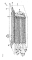
- FIG. 1 shows, for example, a major portion of a lamination-type lithium-ion capacitor 10 is illustrated.
- negative electrodes 12 and positive electrodes 13 are alternately laminated in a state that a separator 11 is interposed between the negative electrode and the positive electrode, which are adjacent to each other.
- a lithium electrode 14 is layered on the separator 11 located on the negative electrode 12 of the structure containing the negative electrodes 12 and the positive electrodes 13, which are alternately laminated.
- Another separator 11 is layered on the lithium electrode 14.
- Each negative electrode 12 includes a negative-electrode current collector 12a and negative-electrode active material layers 12b on both surfaces of the negative-electrode current collector 12a.
- the negative-electrode active material layer 12b is formed by coating surfaces of the negative-electrode current collector 12a with a slurry of a negative electrode active material.
- the negative-electrode current collectors 12a of the negative electrodes 12 are connected in parallel by conductor wires 15.
- Each positive electrode 13 also includes a positive-electrode current collector 13a and positive-electrode active material layers 13b on both surfaces of the positive-electrode current collector 13a.
- the positive-electrode active material layer 13b is also formed by coating a surface of the positive-electrode current collector 13a with a slurry of a positive electrode active material.
- the positive-electrode current collectors 13a of the positive electrodes 13 are also connected in parallel by conductor wires 15.
- the lithium-electrode current collector 14a, as shown in FIG. 1, is connected in parallel to the negative-electrode current collectors 12a by the conductor wires 15.
- FIG. 2 shows a major portion of a film-type lithium-ion capacitor 20.
- negative electrodes 22 and positive electrodes 23 are alternately laminated in a state that a separator 21 is interposed between the negative electrode and the positive electrode, which are located adjacent to each other.
- a lithium electrode 24, as shown in FIG. 2 is provided on a separator 21 in the upper part of the structure including the negative electrodes 22 and the positive electrodes 23, which are alternately laminated.
- Another separator 21 is provided on the lithium electrode 24.
- Each negative electrode 22 includes a negative-electrode current collector 22a and a negative-electrode active material layer 22b layered on the negative-electrode current collector 22a.
- the negative-electrode active material layer 22b is formed by coating surfaces of the negative-electrode current collector 22a with a slurry of a negative electrode active material.
- the negative-electrode current collectors 22a thus structured are provided with terminal connection parts, which are connected together and to a negative electrode terminal 22c.
- Each positive electrode 23 also includes a positive-electrode current collector 23a and positive-electrode active material layers 23b on both surfaces of the positive-electrode current collector 23a.
- the positive-electrode active material layer 23b is also formed by coating surfaces of the positive-electrode current collector 23a with a slurry of a positive electrode active material.
- the positive-electrode current collectors 23a thus structured are provided with terminal connection parts, which are connected together and to a positive electrode terminal 23c, as shown in FIG. 2.
- the lithium-electrode current collector 24a as shown in FIG. 2, is connected together with the terminal connection parts of the negative-electrode current collectors 22a, and connected to a negative electrode terminal 22c.
- the structure of the negative electrode 22, the positive electrode 23, and the lithium electrode 24, which are thus laminated, as shown in FIG. 2, is placed in a deep-drawn laminate film 25.
- the upper end of the lamination structure is sealed with a flat laminate film 26.
- the negative electrode terminal 22c and the positive electrode terminal 23c are extended outside through the sealing parts of the laminate films 25 and 26.
- the laminate films 25 and 26 are indicated by broken lines.
- the cell structure is already described in WO00/07255 , WO03/003395 , JP-A-2004-266 091 , and others.
- the capacitor cell of the invention may take such a cell structure.
- the lithium-ion capacitor thus constructed and the useful effects produced by the lithium-ion capacitor will be described in details by using examples of the lithium-ion capacitor. It should be understood that the present invention is not limited by the examples to be described.
- Graphite KS6 manufactured by TIMCAL Graphite & Carbon was used for the graphite as the negative electrode active material. 88 parts by weight of the above graphite, 5 parts by weight of acetylene black, 3 parts by weight of styrene-butadiene rubber binder, 4 parts by weight of carboxymethyl cellulose, and 200 parts by weight of ion exchanged water were sufficiently mixed to obtain a slurry for the negative electrode.
- the slurry was coated over a negative electrode current collector formed with a copper expanded metal (manufactured by Nippon Metal Industry Co., Ltd.) having a thickness of 32 ⁇ m (porosity of 57 %). Both surfaces of the negative electrode current collector were coated with the slurry by using a roll coater. The negative electrode layer was thus formed and vacuum dried, to thereby obtain a negative electrode having a total thickness (the sum of the negative electrode layer thicknesses on both the surfaces of the current collector and the current collector thickness) of 79 ⁇ m.
- a slurry was obtained by thoroughly mixing 92 parts by weight of commercially available activated carbon powder having a specific surface area of 2000 m 2 /g, 6 parts by weight of acetylene black powder, 7 parts by weight of an acrylic resin binder, 4 parts by weight of carboxymethyl cellulose, and 200 parts by weight of water.
- Both surfaces of an aluminum expanded metal (manufactured by Nippon Metal Industry Co., Ltd.) having a thickness of 38 ⁇ m (porosity of 47 %) were coated with a non-aqueous carbon conductive coating by a roll coater, and dried to thereby obtain a current collector for the positive electrode having a conductive layer formed thereon.
- the total thickness (the sum of the current collector thickness and the conductive layer thickness) was 52 ⁇ m, and most of the through holes of the positive electrode current collector were filled with the conductive coating.
- the slurry of the positive electrode was coated over both surfaces of the positive electrode current collector by means of a roll coater to produce a positive electrode layer.
- the positive electrode layer was vacuum dried to obtain a positive electrode having a total thickness (the sum of the positive electrode layer thicknesses on both surfaces and the conductive layer thicknesses on both the surfaces, and the positive-electrode current collector thickness) of 182 ⁇ m.
- a doping amount of lithium ions which is necessary for measuring a capacitance of the negative electrode per unit weight, was measured.
- the capacitance of the negative electrode per unit weight was set to 5000 F/g.
- a sheet having a size of 1.5 cm x 2.0 cm was cut out from the negative electrode and was used for a negative electrode to be evaluated.
- a test cell was assembled in such a manner that a metal lithium plate having a size of 1.5 cm x 2.0 cm and a thickness of 200 ⁇ m was used as a counter electrode of the negative electrode, with a polyethylene nonwoven fabric having a thickness of 50 ⁇ m being interposed as a separator between the counter electrode and the negative electrode.
- Metal lithium was used as a reference electrode.
- As an electrolyte used was a solution obtained by dissolving LiPF 6 at 1.2 mol/l into a solvent mixture containing ethylene carbonate and diethyl carbonate at the weight ratio of 1:3.
- the test cell was charged at constant current of 10 mA till a potential of the negative electrode reached 25 mV. Then, the cell was charged in a constant current - constant voltage charging mode in which a constant voltage of 25 mA was applied to the cell, and the cell was discharged at 1 mA up to 1.5 V.
- a capacitance of the negative electrode per unit weight was obtained from a discharging time during the potential variation of 0.2 V from the potential of the negative electrode after one minute from the start of discharging. The charging time was controlled so that such a capacity was 5000 F/g, and a charging amount (doping amount of lithium ions) was checked. The doping amount was 400 mAh/g.
- a sheet having a size of 1.5 cm x 2.0 cm was cut out of the positive electrode and was used for a positive electrode to be evaluated.
- a test cell was assembled in such a manner that a metal lithium plate having a size of 1.5 ⁇ 2.0 cm 2 and a thickness of 200 ⁇ m was used as a counter electrode of the positive electrode, with a polyethylene nonwoven fabric having a thickness of 50 ⁇ m being interposed as a separator between the counter electrode and the positive electrode.
- Metal lithium was used as a reference electrode.
- a solution formed by dissolving LiPF 6 at 1.2 mol/l in propylene carbonate was used as an electrolyte.
- the cell was charged at charging current of 1 mA to 3.6 V, and discharged at constant voltage. After a total charging time of 1 hour, the cell was discharged at 1 mA to 2.5 V. A capacitance of the positive electrode per unit weight was obtained from a discharging time between 3.6 V and 2.5 V, and it was 140 F/g.
- the positive electrode was cut out into five sheets each having a size of 2.4 cm x 3.8 cm.
- the negative electrode was cut out into six sheets each having a size of 2.5 cm x 3.9 cm.
- the cutout positive electrode and negative electrode sheets were laminated with separators being interposed therebetween, and the resultant was vacuum dried at 150°C for 12 hours. After it was dried, the separators were located on the uppermost side and lowermost side of the lamination structure, and the four sides of the structure were fastened with a tape, to thereby complete an electrode lamination unit.
- Such metal lithium that the doping amount was 400 mA/g for the negative electrode active material weight was press-contacted with a copper expanded metal having a thickness of 23 ⁇ m.
- a sheet of the metal lithium thus press-contacted was located on the outermost side of the electrode lamination unit in a state that it faced the negative electrode.
- the negative electrodes (five) and the copper expanded metal having the metal lithium foil press-contacted therewith were welded together.
- the electrode lamination unit thus structured, aluminum positive electrode terminals of 3 mm wide x 50 mm long x 0.1 mm thick having sealed portion that had been heat sealed with sealant films were placed on the terminal welded parts (five sheets) of the positive electrode current collector, and ultrasonic-welded together.
- Aluminum positive-electrode terminals of 3 mm wide x 50 mm long x 0.1 mm thick having sealed portion that had been heat sealed with sealant films were placed on the terminal welded parts (six sheets) of the negative current collector, and ultrasonic-welded together.
- the electrode lamination unit was placed between an outer jacket film deep-drawn to 60 mm (vertical) x 30 mm (lateral) x 3 mm (deep), and another outer jacket film which is not deep-drawn.
- the unit was vacuum-impregnated with a solution, the solution formed by dissolving LiPF 6 at 1.2 mol/l into a solvent mixture containing ethylene carbonate and diethyl carbonate at the volume ratio of 1:3. Then, the remaining one side of the outer jacket films was heat sealed at reduced pressure and vacuum sealed to assemble three cells of film-type lithium ion capacitors. It was confirmed that the positive electrode active material weight was larger than the negative electrode active material weight.
- the thus assembled cells were left out for 14 days, and one cell was disassembled. It was confirmed that no metal lithium remained. From this fact, it was considered that the amount of lithium ions, which was necessary for producing a capacitance of 5000F/g per unit weight of the negative electrode active material, was pre-doped through the charging operation. Thereafter, the positive electrode and the negative electrode of one cell were short-circuited, and a potential of the positive electrode was measured. The positive electrode potential was within a range from 0.85 V to 1.0 V, and from this it was confirmed that the potential was 2.0 V or lower.
- the remaining one film-type capacitor cell was charged at constant current of 200 mA till the cell voltage was 3.8 V. Then, it was charged for 30 minutes in a constant current - constant voltage charging mode in which the constant voltage of 3.8 V was applied. Further, the cell was discharged at constant current of 200 mA or 5000 mA till the cell voltage reached 2.2 V.
- the discharging capacity of 200 mA was treated as a low rate capacity, and the discharging capacity of 5000 mA was treated as a high rate capacity.
- the low rate discharging capacity was 16 mAh, and the high rate discharging capacity was 8.5 mAh.
- a retention ratio of the high rate discharging capacity to the low rate discharging capacity was 53.4 %. This value was used as an index for evaluating the rate characteristic.
- the cell was charged at constant current of 200 mA for 30 minutes in a constant current - constant voltage charging mode in which the constant voltage of 3.8 V was applied, and a cycle test was conducted 1000 times in which the cell was discharged at constant current of 20 mA till the cell voltage reached 2.2 V.
- the discharging capacity retention ratio was obtained from a ratio of the discharging capacity of the 1000th cycle to the discharging capacity of the 10th cycle in the cycle test, and it was used as the cycle durability.
- the cycle durability was 98 %.
- the energy density at the low rate was 11.8 Wh/L. From this, it was confirmed that the energy density was high.
- Examples 2 to 6 as shown in FIG. 3, one or a mixture of KS4, KS6, KS15, and KS25 (manufactured by TIMCAL Graphite & Carbon) of which an average distance between 002 lattice planes (d002) was within a range from 0.3356 nm to 0.3358 nm, was used for graphite as a negative electrode active material.
- D 50 was set to 2.9 ⁇ m, 2.4 ⁇ m, 3.0 ⁇ m, 3.7 ⁇ m, 3.9 ⁇ m, i.e., smaller than 4.0 ⁇ m.
- (D 90 -D 10 ) was set to 4.2 ⁇ m, 3.5 ⁇ m, 4.6 ⁇ m, 6.5 ⁇ m, 5.8 ⁇ m, i.e., smaller than 7.0 ⁇ m.
- the doping amounts of lithium ions which are necessary for obtaining a capacitance of 5000 F/g in each negative electrode, as shown in FIG. 3, were adjusted to 420 mAh/g, 440 mAh/g, 430 mAh/g, 410 mAh/g, and 400 mAh/g, respectively.
- the remaining conditions were similar to those in Example 1.
- Comparative Examples 1 to 7 as shown in FIG. 3, one or a mixture of KS4, KS6, KS15, and KS25 (manufactured by TIMCAL Graphite & Carbon) of which an average distance between 002 lattice planes (d002) was within a range from 0.3356 nm to 0.3358 nm, was used for the graphite as the negative electrode active material, as in Examples 1 to 6.
- D 50 was set, except Comparative Example 3, to 4.3° ⁇ m, 4.1 ⁇ m, 5.0 ⁇ m, 6.1 ⁇ m, 8.0 ⁇ m, 11.0 ⁇ m, i.e., larger than 4.0 ⁇ m.
- D 50 was set to 3.9 ⁇ m, smaller than 4.0 ⁇ m, and (D 90 -D 10 ) was 7.1 ⁇ m, larger than 7.0 ⁇ m.
- (D 90 -D 10 ) was set, except Comparative Examples 1 and 2, to 7.1 ⁇ m, 9.6 ⁇ m, 11.5 ⁇ m, 14.1 ⁇ m, and 23.7 ⁇ m, any of those values being larger than 7.0 ⁇ m.
- the doping amounts of lithium ions which are necessary for obtaining a capacitance of 5000 F/g in each negative electrode, as shown in FIG. 3, were adjusted to 390 mAh/g, 410 mAh/g, 410 mAh/g, 410 mAh/g, 390 mAh/g, 380 mAh/g, and 370 mAh/g, respectively.
- the remaining conditions were similar to those in Example 1.
- a phenol resin molding plate of 0.5 mm thick was placed in a Siliconit electric furnace and heat-treated under a nitrogen atmosphere at a rate of 50°C/hour till the temperature reached 550°C, and further heat-treated at a rate of 10°C/hour till the temperature reached 670°C, to thereby synthesize a PAS (an insoluble and infusible base having a polyacene-based skeleton) plate.
- the PAS plate thus formed was crushed by using a ball mill to produce PAS powder having an average particle size of about 4 ⁇ m.
- An H/C ratio of the PAS powder was 0.2.
- Example 8 a cell of Example 8 was manufactured in the same manner as in Example 1, except that the negative electrode was manufactured by using the PAS.
- FIG. 4 shows the low rate discharging capacity, the high rate discharging capacity, the rate characteristic, and the cycle durability of the cells of Examples 1 to 6 and Comparative Examples 1 to 8.
- FIG. 4 shows that when (D 90 -D 10 ) ⁇ 7 ⁇ m, the cycle durability is 90 % or higher and good, and when (D 90 -D 10 ) > 7 ⁇ m, the cycle durability is smaller than 90 % and bad. To secure good cycle durability of the cell, it is essential that (D 90 -D 10 ) ⁇ 7 ⁇ m.
- the resultant lithium-ion capacitor that is high in energy density, output density and cycle durability can be provided.
- FIGS. 3 and 4 show that the use of the graphite for the negative electrode active material provides high energy density, the setting of D 50 to be 4.0 ⁇ m or smaller provides high output density, and the setting of (D 90 -D 10 ) to be 7.0 ⁇ m or smaller provides high cycle durability.
- the present invention is technically useful in the fields including the lithium-ion capacitor.
Landscapes
- Engineering & Computer Science (AREA)
- Power Engineering (AREA)
- Chemical & Material Sciences (AREA)
- Materials Engineering (AREA)
- Microelectronics & Electronic Packaging (AREA)
- Manufacturing & Machinery (AREA)
- Electric Double-Layer Capacitors Or The Like (AREA)
- Secondary Cells (AREA)
- Battery Electrode And Active Subsutance (AREA)
- Cell Electrode Carriers And Collectors (AREA)
Abstract
Description
- The present invention relates to a technology of a lithium-ion capacitor, and more particularly, to a technology which is well adaptable to a negative electrode material of a lithium-ion capacitor.
- The following technologies were investigated by the inventor of the present patent application and are briefly referred to below.
- In the recent situation where the environmental issue, particularly the vehicle-exhaust gas emission, is widely talked about, efforts are made of developing environment-friendly electric vehicles and the like. In the electric vehicle development, the strong development effort is focused on the electricity storage device to be used as a power source. Many types of electricity storage devices have been proposed for replacement of the conventional lead battery, and the papers discussing electrolytes, electrode materials and the like are increasing in number.
-
JP-A-2005-203 130 -
JP-A-10-226 506 -
JP-A-06-052 860 -
JP-A-08-031 420 - The lithium-ion secondary battery or the like is advantageous in that it has high energy density, but has still technical problems. For example, its safety is still uncertain and its cycle life is not long. To cope with this, there has proposed an electric double layer capacitor as a novel electricity storage device. The electric double layer capacitor has a smaller discharging capacity per charge than that of a battery, but it is excellent in instantaneous charging/discharging characteristic and has such excellent output characteristics that it endures several tens of thousands cycles of charging/discharging operations.
- Particularly, as disclosed in International Publication
WO2003/003395 , a novel lithium-ion capacitor is attracting attention in those fields. In the lithium-ion capacitor, a negative electrode is pre-doped with lithium ions to thereby keep a potential of the negative electrode low, and to secure the safety comparable with that of the electric double layer capacitor, high output characteristics, and high energy density. - As described above, various types of next generation electricity storage devices, which will come after the lead battery, have been proposed. However, the technologies of those proposed ones still involve many problems to be solved.
- The lithium-ion capacitor in which the inventor has engaged for its development is also still unsatisfactory in energy density, output density, cycle durability and the like.
- The inventor has estimated that the energy density and the like can be improved by selecting an appropriate material for a negative electrode active material, as in a case of the lithium-ion secondary battery, etc.
- Accordingly, an object of the present invention is to provide a negative electrode material for a lithium-ion capacitor, which is high in energy density, output density and durability.
- Other objects, advantages and features of the invention will be apparent when carefully reading the description to follow and the accompanying drawings.
- In summary, a negative electrode active material for a lithium-ion capacitor is made of graphite having certain diameters.
- The useful effects produced by the invention will be briefly described below.
- Use of the graphite having a predetermined diameter for the negative electrode active material of the lithium-ion capacitor improves the energy density, the output density and the cycle durability at the time of charging and discharging.
-
- FIG. 1
- is a schematic diagram showing a major portion of a lamination-type lithium-ion capacitor according to the present invention;
- FIG. 2
- is a schematic diagram showing a major portion of a laminate film-type lithium-ion capacitor according to the invention;
- FIG. 3
- is a table comparatively showing the details of graphite for a negative electrode active material of the lithium-ion capacitor of the invention and the details of Comparative Examples;
- FIG. 4
- is a table comparatively showing the results arising from the details of the graphite shown in FIG.3 for the negative electrode active material of the lithium-ion capacitor of the invention and from the details of Comparative Examples;
- FIG. 5
- is a graph showing a variation of rate characteristic with respect to D50 in the lithium-ion capacitor using the graphite for the negative electrode active material; and
- FIG. 6
- is a graph showing a variation of cycle durability with respect to (D90-D10) in the lithium-ion capacitor using the graphite for the negative electrode active material.
- An embodiment of the present invention will be described with reference to the accompanying drawings.
- A lithium-ion capacitor of the invention includes a positive electrode, a negative electrode and an electrolyte. In the embodiment, an aprotic organic solution containing a lithium salt is used as the electrolyte.
- A material which allows lithium ions and/or anions to be reversibly doped thereinto and de-doped therefrom is used for a positive electrode active material. A material which allows lithium ions to be reversibly doped thereinto and de-doped therefrom is used for a negative electrode active material.
- In the specification of the present patent application, the term "dope" involves "occlude", "carry", "absorb" or "insert", and specifically a phenomenon where lithium ions and/or anions enter the positive electrode active material or lithium ions enter the negative electrode active material. The term "de-dope" involves "release" and "desorb", and specifically a phenomenon where lithium ions or anions desorb from the positive electrode active material or lithium ions desorb from the negative electrode active material.
- The term "positive electrode" means an electrode from which current flows out when the lithium-ion capacitor is discharged, and the term "negative electrode" means an electrode to which current flows when the lithium-ion capacitor is discharged.
- A potential of the positive electrode and that of the negative electrode after those electrodes are short-circuited are preferably 2 V (vs. Li/Li+) or lower, for example. More specifically, in the lithium-ion capacitor of the invention, it is preferable to dope the negative electrode and/or the positive electrode with lithium ions so that after the positive electrode and the negative electrode are short-circuited, the potential of the positive electrode is 2 V (vs. Li/Li+) or lower, for example.
- In the case of the capacitor having not been doped with lithium ions, unlike the construction mentioned above, the potentials of the positive electrode and the negative electrode are 3 V, and before the charging of the capacitor, the potential of the positive electrode is 3 V after short-circuiting the positive electrode and the negative electrode. As in the invention, the doping of lithium ions lowers the electrode potential to be 3 V (vs. Li/Li+) or lower, preferably 2 V (Li/Li+) or lower to improve the capacity.
- In the specification, the wording "the potential of the positive electrode after short-circuiting between the positive electrode and the negative electrode is 2 V (vs. Li/Li+) or lower " means that the potential of the positive electrode, which is obtained by either of the following methods, is 2 V (vs. Li/Li+) or lower.
- The first method is as follows. After the doping of lithium ions, a positive electrode terminal and a negative electrode terminal of a capacitor cell (to be referred frequently to as a cell) of the lithium-ion capacitor are directly connected by a conductor to be short-circuited. This short-circuiting state is left to stand for 12 hours or longer. Thereafter, the short-circuiting state is canceled and the potential of the positive electrode is measured within a time range from 0.5 to 1.5 hours.
- The second method is as follows. By using a charging/discharging apparatus, the capacitor is discharged to 0 V at a constant current for 12 hours or longer. Then, the positive electrode terminal and the negative electrode terminal are coupled together by means of a conductor to be short-circuited. In this state, the capacitor is left to stand for 12 hours or longer and the short-circuiting of those electrodes is canceled. The potential of the positive electrode is measured within a time range from 0.5 to 1.5 hours.
- Generally, the upper limit of the charging voltage is determined by such a voltage as not to cause the decomposition of the electrolyte owing to increase of the positive electrode potential. When the positive electrode potential is set at the upper limit, the charging voltage may be increased by decrease of the negative electrode potential. If the potential of the positive electrode after short-circuiting is lowered to be 3 V (vs. Li/Li+) or lower, preferably 2 V (vs. Li/Li+) or lower, the utilized capacity of the positive electrode increases by the potential decrease and the capacity of the capacitor becomes high.
- In a so-called hybrid capacitor, activated carbon is used for a positive electrode and graphite or hard carbon, which is used in a lithium-ion secondary battery, is used for a negative electrode. In such a hybrid capacitor, the activated carbon or the carbon material has usually a potential at 3 V (vs. Li/Li+) or therearound. Therefore, even if the terminals of the positive electrode and the negative electrode are short-circuited, the potentials at about 3 V (vs. Li/Li+) of those electrodes remain unchanged.
- On the basis of those facts, in the lithium-ion capacitor of the invention, the potential of the positive electrode is lowered to 2 V (vs. Li/Li+) or lower when the electrodes are short-circuited by doping the negative electrode with lithium ions, which are supplied from a lithium ion source, e.g., metal lithium, which is separately provided.
- This means the negative electrode and/or the positive electrode of the cell of the lithium-ion capacitor is doped, in advance, with lithium ions supplied from the lithium ion source. With the pre-doping of the lithium ions, the potential of the positive electrode is lowered to be 2 V (vs. Li/Li+) or lower after the positive electrode and the negative electrode are short-circuited.
- In the invention, one or both of the negative electrode and the positive electrode may be doped with the lithium ions. In this case, when the potential of the positive electrode is excessively lowered by increasing the doping amount of lithium ions, problems sometimes arise. For example, the lithium ions are irreversibly consumed and the cell capacity lowers. Accordingly, it is necessary to control the doping amounts of lithium ions at the negative electrode and the positive electrode so as not cause such a problem. The controlling of the doping amounts of the lithium ions at the electrodes makes the cell forming process complicated. To avoid this, the lithium ions are preferably doped only into the negative electrode.
- In constructing the lithium-ion capacitor of the invention, it is preferable that the capacitance of the negative electrode per unit weight is not less than three times as large as the capacitance of the positive electrode per unit weight. Further, it is preferable that the weight of the positive electrode active material is larger than that of the negative electrode active material. By so selecting the capacitance and the weight, the lithium-ion capacitor of high voltage and high capacity is obtained.
- As just mentioned, it is preferable that the weight of the positive electrode active material is larger than that of the negative electrode active material. Preferably, the former is 1.1 to 10 times as large as the latter. In the case of less than 1.1 times, the capacity difference is small. In the case of 10 times or larger, the cell capacity becomes sometimes small. Further, in this case, the thickness difference between the positive electrode and the negative electrode is too large. This is not desirable in the cell construction.
- In the present invention, the capacitance and the capacity of the cell of the lithium-ion capacitor are defined as follows.
- The capacitance of the cell indicates an amount of electricity which flows through the cell per unit voltage of the cell, i.e., a slope of the discharging curve, and its unit is F (farad). The capacitance of the cell per unit weight is obtained by dividing the capacitance of the cell by the sum of the weights of the positive electrode active material and the negative electrode active material, which are loaded in the cell, and the unit thereof is F/g.
- The capacitance of the positive electrode or the negative electrode indicates an amount of electricity which flows through the cell per unit voltage of the positive electrode or the negative electrode, i.e., a slope of the discharging curve, and the unit thereof is F (farad). The capacitance of the positive electrode or the negative electrode per unit weight is obtained by dividing the capacitance of the positive electrode or the negative electrode by the weight of the positive electrode active material or the negative electrode active material, which is loaded in the cell, and the unit thereof is F/g.
- The cell capacity is a product of a difference between the cell voltage at the time of starting the discharging operation and that at the time of ending the discharging operation, i.e., amount of voltage change, and a capacitance of the cell, and the unit of the cell capacity is C (coulomb). 1 C is a quantity of charge when current of 1 A flows for one second, and in the specification it is converted and expressed in terms of mAh in some cases.
- The positive electrode capacity is a product of the capacitance of the positive electrode and a difference between the positive electrode potential at the time of starting the discharging operation and that at the time of ending the discharging operation (amount of change of the positive electrode potential), and the unit of the positive electrode capacity is C or mAh. The negative electrode capacity is a product of the capacitance of the negative electrode and a difference between the negative electrode potential at the time of starting the discharging operation and that at the time of ending the discharging operation (amount of change of the negative electrode potential), and the unit of the negative electrode capacity is C or mAh. The cell capacity, the positive electrode capacity and the negative electrode capacity are equal to one another.
- In the lithium-ion capacitor of the invention, the negative electrode and/or the positive electrode is doped with lithium ions in advance. The doping method is not particularly limited.
- A lithium ion source, such as metal lithium, which is capable of supplying lithium ions may be located as a lithium electrode within the capacitor cell. To dope the electrode, the lithium electrode is preferably brought into physical contact (short-circuiting) or brought into contact by electrochemical means with the positive electrode and/or the negative electrode.
- An amount of the lithium ion source (weight of metal lithium, for example) is sufficient if it produces a predetermined capacity of the negative electrode.
- The lithium ion source may be formed on a lithium electrode current collector made of a conductive material having through holes. The conductive material having through holes may be a metal material with through holes, which does not react with the lithium ion source, for example, a stainless steel mesh.
- In the case of the large capacity capacitor cell having a multi-layer structure, the positive electrode and the negative electrode are provided with a positive electrode current collector and a negative electrode current collector respectively for feeding and receiving electricity. In the cell thus structured, for example, the lithium electrode is located at a position where it faces the negative electrode, and lithium ions are electrochemically supplied to the negative electrode.
- In this case, a substrate having through holes, i.e. holes passing through the substrate from the front to the reverse side of the substrate, such as an expanded metal, is preferably used for the positive electrode current collector and the negative electrode current collector, and a lithium electrode is located facing the negative electrode and/or the positive electrode. The form, the number and the like of the through holes are not limited to specific ones in particular. The through holes may be formed such that lithium ions in an electrolyte are movable from one side to the other side of the electrode via the through holes without interruption of the electrode current collectors.
- In the lithium-ion capacitor of the invention, the lithium ions can be uniformly doped even when the lithium electrode for doping the negative electrode and/or the positive electrode with lithium ions is locally located in the cell.
- Accordingly, even in the large capacity cell of the type in which the positive electrode and the negative electrode are layered or wound, the negative electrode and/or the positive electrode may be smoothly and uniformly doped with the lithium ions by locating the lithium electrode at a part of the outermost peripheral or the outermost side of the cell.
- Various kinds of materials that are widely proposed in the lithium battery may be used for forming the electrode current collectors. Aluminum, stainless steel or the like may be used for the positive electrode current collector, and stainless steel, copper, nickel or the like may be used for the negative electrode current collector.
- When lithium ions are doped through the electrochemical contact of the electrode(s) with the lithium ion source located in the cell, the lithium ion source may be a material containing at least lithium elements and capable of supplying lithium ions, such as metal lithium or lithium-aluminum alloy.
- In the lithium-ion capacitor of the invention, graphite is used for the negative electrode active material. The graphite is used of which an average distance between 002 lattice planes, i.e. d002, is within a range from 0.335 nm to 0.337 nm. There is no other prior art than the present invention in which such graphite is used for the negative electrode of the lithium-ion capacitor, so far as the present inventor knows.
- The average distance d002 of the graphite as the negative electrode active material was measured by the powder X-ray diffraction equipment, RINT-UltimaIII (manufactured by Rigaku Corporation) according to the Gakushin method (Japan Society for the Promotion of Science, N. 117 Committee, Carbon 1963 (No. 36)). The inventor has found that the energy density of the lithium-ion capacitor can be increased by using the graphite as defined above for the negative electrode of the lithium-ion capacitor. This would be due to the fact that the charging and discharging capacity of the graphite material is high, 300 mAh/g to 372 mAh/g, and the potential for doping/de-doping the lithium ions is almost constant over a wide range of charge/discharge depth.
- It has been also found that high output density is obtained by specifying the particle size distribution of the graphite. In other words, it has been found that the particle size distribution of the graphite of the negative electrode is important to obtain high output density.
- In the invention, the high output density is obtained by selecting the particle size of the graphite to be smaller than that in the conventional case. It has been found that the average particle diameter of the graphite is selected such that D50 is defined as 0 < D50 ≤ 4.0 µm. The D50 value indicates the value at which 50 % by volume of the particles in the measured sample have a particle diameter smaller than or equal to the value.
- It has been also confirmed that when the graphite material as mentioned above is used, the charge transfer resistance little varies within a potential range where the potential is almost constant. With such a feature, stable outputting of electric power is ensured within a wide charging/discharging depth range. That is, it is possible to provide the lithium-ion capacitor capable of outputting stable and high electric power.
- It has been also found that the durability of the lithium-ion capacitor is improved by narrowing the particle size distribution of the graphite. This fact would be due to the fact that if the particle size distribution is narrowed, a variation of the charge/discharge depths of the particles of the negative electrode material is lessened, and load applied to each particle of the active material is stabilized. As a result, the charging/discharging operation is stably performed even if the charging/discharging operation is repeated.
- Specifically, the cycle durability was improved when a difference between the particle size of the graphite used for the negative electrode active material is placed within a range of 0 < (D90-D10) ≤ 7.0 µm. The D10 value and the D90 value indicate the values at which 10 % and 90 % by volume of the particles in the measured sample have a particle diameter smaller than or equal to these values.
- The particle size distribution of the graphite used for the negative electrode active material was measured in such a manner that the negative electrode active material was sufficiently dispersed into water by ultrasonication, and D10, D50 and D90 were measured by using a laser diffraction particle size distribution measuring instrument (Microtrac, manufactured by Nikkiso Co., Ltd.).
- The negative electrode in the invention, which is formed of the graphite powder as the negative electrode active material having the particle size property as mentioned above. An appropriate conventional process may be used for forming the negative electrode. In an example process, the negative electrode active material powder, a binder, and if necessary, a conductive material and a thickening agent (carboxymethyl cellulose (CMC), etc.) are dispersed into a water or an organic solvent to obtain a slurry. The slurry is coated over the current collector, or the slurry is molded into a sheet and the sheet is stuck onto the current collector.
- Examples of the binder used when the negative electrode is formed include a rubber-based binder such as SBR; a fluorine contained resin such as polytetrafluoroethylene or polyvinylidene fluoride; a thermoplastic resin such as polypropylene or polyethylene; and an acrylic resin. A preferable amount of the binder to be added is 2 to 40 % by weight of the negative electrode active material although it varies depending on an electric conductivity of the negative electrode active material, an electrode shape, and the like.
- Examples of the conductive material, which is used if necessary, include an acetylene black and metal powder. A preferable amount of the conductive material to be added is 2 to 40 % by weight of the negative electrode active material although it varies depending on an electric conductivity of the negative electrode active material, an electrode shape, and the like.
- In the field of the conventional lithium-ion secondary battery, many prior arts which specify the particle size of the negative electrode active material have been presented as in the patent publications already referred to. In all of those arts, the lithium source depends on the positive electrode. In these cases, when the particle size of the negative electrode active material is within the range mentioned above, the irreversible capacity is large and an insufficient charging/discharging capacity is obtained. As a result, the resultant capacitor is almost impossible in practical use. This fact was confirmed.
- In this connection, it is noted that in the lithium-ion capacitor of the invention the lithium ion source does not depend on the positive electrode, and that it is allowed to dope the extra amount of lithium ions corresponding to the irreversible capacity and the capacitor can be actually used with no lowering of the energy density.
- In the lithium-ion capacitor of the invention, the positive electrode active material used for forming the positive electrode is not limited in particular as long as it is a material allowing lithium ions and anions such as tetrafluoroborate to be reversibly doped.
- The positive electrode active material is preferably an activated carbon, a conductive polymer, a polyacene-based material, or the like. In the positive electrode active material, the particle size of the activated carbon, for example, may be selected from a variety of particle sizes, generally used. Its D50 is 2 µm or larger, more preferably 2 to 50 µm, and particularly preferably 2 to 20 µm. The average pore size of the activated carbon is preferably 10 nm or smaller, and the specific surface area thereof is preferably 600 to 3000 m2/gm, particularly 1300 to 2500 m2/gm.
- The positive electrode, which is formed of the positive electrode active material powder mentioned above, may be formed by an appropriate conventional forming process, as in the case of the negative electrode. In an example process, the positive electrode active material powder, a binder, and if necessary, a conductive material and a thickening agent (carboxymethyl cellulose (CMC), etc.) are dispersed into a water or an organic solvent to obtain a slurry. The slurry is coated over the current collector, or the slurry is molded into a sheet in advance and the sheet is stuck onto the current collector.
- Examples of the available binder include a rubber-based binder such as SBR; a fluorine containing resin such as polytetrafluoroethylene or polyvinylidene fluoride; a thermoplastic resin such as polypropylene or polyethylene; and an acrylic resin.
- A preferable amount of the binder material to be added is 2 to 40 % by weight of the positive electrode active material although it varies depending on an electric conductivity of the positive electrode active material, an electrode shape, and the like. Examples of the conductive material, which is used if necessary, include an acetylene black, graphite, and metal powder. A preferable amount of the conductive material to be added is 2 to 40 % by weight of the positive electrode active material although it varies depending on an electric conductivity of the positive electrode active material, an electrode shape, and the like.
- In the lithium-ion capacitor of the invention, an aprotic organic solvent forming an aprotic organic solvent electrolyte may be used for the electrolyte. Examples of the aprotic organic solvent include ethylene carbonate, propylene carbonate, dimethyl carbonate, diethyl carbonate, γ-butyrolactone, acetonitrile, dimethoxyethane, tetrahydrofulan, dioxolan, methylene chloride, and sulfolane. In addition, a mixed solvent having at least two types of these aprotic organic solvents can be used.
- An electrolyte to be dissolved in the single or mixed solvent may be any type of electrolytes as long as it is able to generate lithium ions. Examples of such type of electrolyte include LiClO4, LiAsF6, LiBF4, LiPF6, LiN(C2F5SO2)2, and LiN(CF3SO2)2.
- The electrolyte and the solvent, after sufficiently dehydrated, must be mixed into an electrolyte. A concentration of the electrolyte is preferably at least 0.1 mol/l, more preferably within a range from 0.5 to 1.5 mol/l, in order to reduce the internal resistance of the electrolyte.
- The lithium-ion capacitor of the invention is suitable for a capacitor cell of a large capacity, such as a wound-type cylindrical cell in which strip-like positive and negative electrodes are wound with a separator interposed between them, a lamination-type prismatic cell in which plate-like positive and negative electrodes are laminated at least three layers with a separator interposed between them, and a film-type cell in which a lamination is sealed in an outer jacket film, the lamination being configured such that plate-like positive and negative electrodes are laminated at least three layers with a separator interposed between them.
- FIG. 1 shows, for example, a major portion of a lamination-type lithium-
ion capacitor 10 is illustrated. In the lamination-type structure, as shown FIG. 1,negative electrodes 12 andpositive electrodes 13 are alternately laminated in a state that aseparator 11 is interposed between the negative electrode and the positive electrode, which are adjacent to each other. As shown in FIG. 1, alithium electrode 14 is layered on theseparator 11 located on thenegative electrode 12 of the structure containing thenegative electrodes 12 and thepositive electrodes 13, which are alternately laminated. Anotherseparator 11 is layered on thelithium electrode 14. - Each
negative electrode 12 includes a negative-electrodecurrent collector 12a and negative-electrode active material layers 12b on both surfaces of the negative-electrodecurrent collector 12a. The negative-electrodeactive material layer 12b is formed by coating surfaces of the negative-electrodecurrent collector 12a with a slurry of a negative electrode active material. The negative-electrodecurrent collectors 12a of thenegative electrodes 12 are connected in parallel byconductor wires 15. - Each
positive electrode 13 also includes a positive-electrodecurrent collector 13a and positive-electrode active material layers 13b on both surfaces of the positive-electrodecurrent collector 13a. The positive-electrodeactive material layer 13b is also formed by coating a surface of the positive-electrodecurrent collector 13a with a slurry of a positive electrode active material. The positive-electrodecurrent collectors 13a of thepositive electrodes 13 are also connected in parallel byconductor wires 15. - The
lithium electrode 14, which is located on theseparator 11 layered on thenegative electrode 12 located in the upper part of the lamination structure including thenegative electrodes 12 and thepositive electrodes 13, includes ametal lithium 14b as a lithium ion source, which is layered on a surface of a lithium-electrodecurrent collector 14a. The lithium-electrodecurrent collector 14a, as shown in FIG. 1, is connected in parallel to the negative-electrodecurrent collectors 12a by theconductor wires 15. - FIG. 2 shows a major portion of a film-type lithium-
ion capacitor 20. In the structure of FIG. 2,negative electrodes 22 andpositive electrodes 23 are alternately laminated in a state that aseparator 21 is interposed between the negative electrode and the positive electrode, which are located adjacent to each other. Alithium electrode 24, as shown in FIG. 2, is provided on aseparator 21 in the upper part of the structure including thenegative electrodes 22 and thepositive electrodes 23, which are alternately laminated. Anotherseparator 21 is provided on thelithium electrode 24. - Each
negative electrode 22 includes a negative-electrodecurrent collector 22a and a negative-electrodeactive material layer 22b layered on the negative-electrodecurrent collector 22a. The negative-electrodeactive material layer 22b is formed by coating surfaces of the negative-electrodecurrent collector 22a with a slurry of a negative electrode active material. The negative-electrodecurrent collectors 22a thus structured are provided with terminal connection parts, which are connected together and to anegative electrode terminal 22c. - Each
positive electrode 23 also includes a positive-electrodecurrent collector 23a and positive-electrode active material layers 23b on both surfaces of the positive-electrodecurrent collector 23a. The positive-electrodeactive material layer 23b is also formed by coating surfaces of the positive-electrodecurrent collector 23a with a slurry of a positive electrode active material. The positive-electrodecurrent collectors 23a thus structured are provided with terminal connection parts, which are connected together and to apositive electrode terminal 23c, as shown in FIG. 2. - The
lithium electrode 24, which is provided on theseparator 21 in the upper part of the structure including thenegative electrodes 22 and thepositive electrodes 23, includes ametal lithium 24b as a lithium ion source, which is provided on a surface of the lithium-electrodecurrent collector 24a. The lithium-electrodecurrent collector 24a, as shown in FIG. 2, is connected together with the terminal connection parts of the negative-electrodecurrent collectors 22a, and connected to anegative electrode terminal 22c. - The structure of the
negative electrode 22, thepositive electrode 23, and thelithium electrode 24, which are thus laminated, as shown in FIG. 2, is placed in a deep-drawnlaminate film 25. The upper end of the lamination structure is sealed with aflat laminate film 26. Thenegative electrode terminal 22c and thepositive electrode terminal 23c are extended outside through the sealing parts of thelaminate films laminate films - The cell structure is already described in
WO00/07255 WO03/003395 JP-A-2004-266 091 - The lithium-ion capacitor thus constructed and the useful effects produced by the lithium-ion capacitor will be described in details by using examples of the lithium-ion capacitor. It should be understood that the present invention is not limited by the examples to be described.
- Graphite KS6 (manufactured by TIMCAL Graphite & Carbon) was used for the graphite as the negative electrode active material. 88 parts by weight of the above graphite, 5 parts by weight of acetylene black, 3 parts by weight of styrene-butadiene rubber binder, 4 parts by weight of carboxymethyl cellulose, and 200 parts by weight of ion exchanged water were sufficiently mixed to obtain a slurry for the negative electrode.
- The slurry was coated over a negative electrode current collector formed with a copper expanded metal (manufactured by Nippon Metal Industry Co., Ltd.) having a thickness of 32 µm (porosity of 57 %). Both surfaces of the negative electrode current collector were coated with the slurry by using a roll coater. The negative electrode layer was thus formed and vacuum dried, to thereby obtain a negative electrode having a total thickness (the sum of the negative electrode layer thicknesses on both the surfaces of the current collector and the current collector thickness) of 79 µm.
- An average distance between 002 lattice planes, i.e., d002, of the negative electrode active material was 0.3358 nm, and for the particle size distribution, D10 = 1.6 µm, D50 = 3.4 µm, and (D90-D10) = 4.9 µm.
- A slurry was obtained by thoroughly mixing 92 parts by weight of commercially available activated carbon powder having a specific surface area of 2000 m2/g, 6 parts by weight of acetylene black powder, 7 parts by weight of an acrylic resin binder, 4 parts by weight of carboxymethyl cellulose, and 200 parts by weight of water. Both surfaces of an aluminum expanded metal (manufactured by Nippon Metal Industry Co., Ltd.) having a thickness of 38 µm (porosity of 47 %) were coated with a non-aqueous carbon conductive coating by a roll coater, and dried to thereby obtain a current collector for the positive electrode having a conductive layer formed thereon. The total thickness (the sum of the current collector thickness and the conductive layer thickness) was 52 µm, and most of the through holes of the positive electrode current collector were filled with the conductive coating.
- The slurry of the positive electrode was coated over both surfaces of the positive electrode current collector by means of a roll coater to produce a positive electrode layer. The positive electrode layer was vacuum dried to obtain a positive electrode having a total thickness (the sum of the positive electrode layer thicknesses on both surfaces and the conductive layer thicknesses on both the surfaces, and the positive-electrode current collector thickness) of 182 µm.
- A doping amount of lithium ions, which is necessary for measuring a capacitance of the negative electrode per unit weight, was measured. In the measurement, the capacitance of the negative electrode per unit weight was set to 5000 F/g. A sheet having a size of 1.5 cm x 2.0 cm was cut out from the negative electrode and was used for a negative electrode to be evaluated.
- A test cell was assembled in such a manner that a metal lithium plate having a size of 1.5 cm x 2.0 cm and a thickness of 200 µm was used as a counter electrode of the negative electrode, with a polyethylene nonwoven fabric having a thickness of 50 µm being interposed as a separator between the counter electrode and the negative electrode. Metal lithium was used as a reference electrode. As an electrolyte used was a solution obtained by dissolving LiPF6 at 1.2 mol/l into a solvent mixture containing ethylene carbonate and diethyl carbonate at the weight ratio of 1:3.
- The test cell was charged at constant current of 10 mA till a potential of the negative electrode reached 25 mV. Then, the cell was charged in a constant current - constant voltage charging mode in which a constant voltage of 25 mA was applied to the cell, and the cell was discharged at 1 mA up to 1.5 V. A capacitance of the negative electrode per unit weight was obtained from a discharging time during the potential variation of 0.2 V from the potential of the negative electrode after one minute from the start of discharging. The charging time was controlled so that such a capacity was 5000 F/g, and a charging amount (doping amount of lithium ions) was checked. The doping amount was 400 mAh/g.
- A sheet having a size of 1.5 cm x 2.0 cm was cut out of the positive electrode and was used for a positive electrode to be evaluated. A test cell was assembled in such a manner that a metal lithium plate having a size of 1.5 × 2.0 cm2 and a thickness of 200 µm was used as a counter electrode of the positive electrode, with a polyethylene nonwoven fabric having a thickness of 50 µm being interposed as a separator between the counter electrode and the positive electrode. Metal lithium was used as a reference electrode. A solution formed by dissolving LiPF6 at 1.2 mol/l in propylene carbonate was used as an electrolyte.
- The cell was charged at charging current of 1 mA to 3.6 V, and discharged at constant voltage. After a total charging time of 1 hour, the cell was discharged at 1 mA to 2.5 V. A capacitance of the positive electrode per unit weight was obtained from a discharging time between 3.6 V and 2.5 V, and it was 140 F/g.
- The positive electrode was cut out into five sheets each having a size of 2.4 cm x 3.8 cm. The negative electrode was cut out into six sheets each having a size of 2.5 cm x 3.9 cm. The cutout positive electrode and negative electrode sheets were laminated with separators being interposed therebetween, and the resultant was vacuum dried at 150°C for 12 hours. After it was dried, the separators were located on the uppermost side and lowermost side of the lamination structure, and the four sides of the structure were fastened with a tape, to thereby complete an electrode lamination unit.
- Such metal lithium that the doping amount was 400 mA/g for the negative electrode active material weight was press-contacted with a copper expanded metal having a thickness of 23 µm. A sheet of the metal lithium thus press-contacted was located on the outermost side of the electrode lamination unit in a state that it faced the negative electrode. The negative electrodes (five) and the copper expanded metal having the metal lithium foil press-contacted therewith were welded together.
- In the electrode lamination unit thus structured, aluminum positive electrode terminals of 3 mm wide x 50 mm long x 0.1 mm thick having sealed portion that had been heat sealed with sealant films were placed on the terminal welded parts (five sheets) of the positive electrode current collector, and ultrasonic-welded together. Aluminum positive-electrode terminals of 3 mm wide x 50 mm long x 0.1 mm thick having sealed portion that had been heat sealed with sealant films were placed on the terminal welded parts (six sheets) of the negative current collector, and ultrasonic-welded together. The electrode lamination unit was placed between an outer jacket film deep-drawn to 60 mm (vertical) x 30 mm (lateral) x 3 mm (deep), and another outer jacket film which is not deep-drawn.
- After one side of the terminal part of the outer jacket films and other two sides thereof were heat sealed, the unit was vacuum-impregnated with a solution, the solution formed by dissolving LiPF6 at 1.2 mol/l into a solvent mixture containing ethylene carbonate and diethyl carbonate at the volume ratio of 1:3. Then, the remaining one side of the outer jacket films was heat sealed at reduced pressure and vacuum sealed to assemble three cells of film-type lithium ion capacitors. It was confirmed that the positive electrode active material weight was larger than the negative electrode active material weight.
- The thus assembled cells were left out for 14 days, and one cell was disassembled. It was confirmed that no metal lithium remained. From this fact, it was considered that the amount of lithium ions, which was necessary for producing a capacitance of 5000F/g per unit weight of the negative electrode active material, was pre-doped through the charging operation. Thereafter, the positive electrode and the negative electrode of one cell were short-circuited, and a potential of the positive electrode was measured. The positive electrode potential was within a range from 0.85 V to 1.0 V, and from this it was confirmed that the potential was 2.0 V or lower.
- The remaining one film-type capacitor cell was charged at constant current of 200 mA till the cell voltage was 3.8 V. Then, it was charged for 30 minutes in a constant current - constant voltage charging mode in which the constant voltage of 3.8 V was applied. Further, the cell was discharged at constant current of 200 mA or 5000 mA till the cell voltage reached 2.2 V. The discharging capacity of 200 mA was treated as a low rate capacity, and the discharging capacity of 5000 mA was treated as a high rate capacity.
- The low rate discharging capacity was 16 mAh, and the high rate discharging capacity was 8.5 mAh. A retention ratio of the high rate discharging capacity to the low rate discharging capacity was 53.4 %. This value was used as an index for evaluating the rate characteristic.
- The cell was charged at constant current of 200 mA for 30 minutes in a constant current - constant voltage charging mode in which the constant voltage of 3.8 V was applied, and a cycle test was conducted 1000 times in which the cell was discharged at constant current of 20 mA till the cell voltage reached 2.2 V. The discharging capacity retention ratio was obtained from a ratio of the discharging capacity of the 1000th cycle to the discharging capacity of the 10th cycle in the cycle test, and it was used as the cycle durability. The cycle durability was 98 %.
- The energy density at the low rate was 11.8 Wh/L. From this, it was confirmed that the energy density was high.
- In Examples 2 to 6, as shown in FIG. 3, one or a mixture of KS4, KS6, KS15, and KS25 (manufactured by TIMCAL Graphite & Carbon) of which an average distance between 002 lattice planes (d002) was within a range from 0.3356 nm to 0.3358 nm, was used for graphite as a negative electrode active material. D50 was set to 2.9 µm, 2.4 µm, 3.0 µm, 3.7 µm, 3.9 µm, i.e., smaller than 4.0 µm.
- (D90-D10) was set to 4.2 µm, 3.5 µm, 4.6 µm, 6.5 µm, 5.8 µm, i.e., smaller than 7.0 µm. The doping amounts of lithium ions, which are necessary for obtaining a capacitance of 5000 F/g in each negative electrode, as shown in FIG. 3, were adjusted to 420 mAh/g, 440 mAh/g, 430 mAh/g, 410 mAh/g, and 400 mAh/g, respectively. The remaining conditions were similar to those in Example 1.
- In Comparative Examples 1 to 7, as shown in FIG. 3, one or a mixture of KS4, KS6, KS15, and KS25 (manufactured by TIMCAL Graphite & Carbon) of which an average distance between 002 lattice planes (d002) was within a range from 0.3356 nm to 0.3358 nm, was used for the graphite as the negative electrode active material, as in Examples 1 to 6. D50 was set, except Comparative Example 3, to 4.3°µm, 4.1 µm, 5.0 µm, 6.1 µm, 8.0 µm, 11.0 µm, i.e., larger than 4.0 µm. In Comparative Example 3, D50 was set to 3.9 µm, smaller than 4.0 µm, and (D90-D10) was 7.1 µm, larger than 7.0 µm.
- Further, (D90-D10) was set, except Comparative Examples 1 and 2, to 7.1 µm, 9.6 µm, 11.5 µm, 14.1 µm, and 23.7 µm, any of those values being larger than 7.0 µm. In Comparative Examples 1 to 7, the doping amounts of lithium ions, which are necessary for obtaining a capacitance of 5000 F/g in each negative electrode, as shown in FIG. 3, were adjusted to 390 mAh/g, 410 mAh/g, 410 mAh/g, 410 mAh/g, 390 mAh/g, 380 mAh/g, and 370 mAh/g, respectively. The remaining conditions were similar to those in Example 1.
- A phenol resin molding plate of 0.5 mm thick was placed in a Siliconit electric furnace and heat-treated under a nitrogen atmosphere at a rate of 50°C/hour till the temperature reached 550°C, and further heat-treated at a rate of 10°C/hour till the temperature reached 670°C, to thereby synthesize a PAS (an insoluble and infusible base having a polyacene-based skeleton) plate. The PAS plate thus formed was crushed by using a ball mill to produce PAS powder having an average particle size of about 4 µm. An H/C ratio of the PAS powder was 0.2.
- 88 parts by weight of the PAS powder as the negative electrode active material, 5 parts by weight of acetylene black, 3 parts by weight of a styrene-butadiene rubber binder, 4 parts by weight of carboxymethyl cellulose, and 200 parts by weight of ion exchanged water were sufficiently mixed to obtain a slurry. A current collector was coated with the slurry to form a negative electrode, as in Example 1. Thus, a cell of Example 8 was manufactured in the same manner as in Example 1, except that the negative electrode was manufactured by using the PAS.
- X-ray diffraction of the negative electrode active material was measured, and the diffraction peak was considerably broad. An average distance between 002 lattice planes (d002) was larger than 0.337 nm, and this figure clearly shows that the material is not graphite. For the particle size distribution, D10 = 2.0 µm, D50 = 3.8 µm, and D90 = 6.9 µm, and (D90-D10) = 4.9 µm. The charging time was controlled so that 5000 F/g was reached, and the doping amount was adjusted. The result is that 5000 F/g could not be reached, and 670 F/g was reached for the doping amount of 420 mAh/g.
- FIG. 4 shows the low rate discharging capacity, the high rate discharging capacity, the rate characteristic, and the cycle durability of the cells of Examples 1 to 6 and Comparative Examples 1 to 8.
- As seen from the results shown in FIGS. 3 and 4, when D50 is 4.3 µm and 4.1 µm, i.e., larger than 4.0 µm, the rate characteristic lowers to be 46 % and 49 %, i.e., below 50 %, as shown in Comparative Examples 1 and 2. As seen from Examples 1 to 6, when D50 ≤ 4.0 µm as in the case of D50 = 3.9 µm and the like, the rate characteristic is 50 % or higher, excellent.
- As seen from FIGS. 3 and 4, when D50 ≤ 4.0 µm, the rate characteristic is 50 % or higher, excellent. When D50 > 4.0 µm, the rate characteristic is lower than 50 %, and bad. From this fact, it is found that to construct a cell having the excellent rate characteristic and high output density, it is essential that D50 ≤ 4.0 µm.
- In Comparative Example 3, D50 = 3.9 µm and this figure is smaller than 4.0 µm, and (D90-D10) = 7.1 µm, and this figure is larger than 7.0 µm. In Examples 1 to 6 where (D90-D10) is 7.0 µm or smaller, and the cycle durability is 90 % or higher and good in all of those examples. In Comparative Example 3, the cycle durability is 89 %, i.e., below 90 %.
- In Comparative Examples 4 to 7, D50 is larger than 4.0 µm and (D90-D10) is also larger than 7.0 µm, the rate characteristic lowers to be much smaller than 50 %, and the cycle durability also lowers to be much smaller than 90 %, as clearly seen from FIG. 4.
- FIG. 4 shows that when (D90-D10) ≤ 7 µm, the cycle durability is 90 % or higher and good, and when (D90-D10) > 7 µm, the cycle durability is smaller than 90 % and bad. To secure good cycle durability of the cell, it is essential that (D90-D10) ≤ 7 µm.
- In FIG. 5, a relationship between D50 and the rate characteristic is tabulated so as to be readily understood, and in FIG. 6, a relationship between (D90-D10) and the cycle durability is tabulated so as to be readily understood.
- In Comparative Example 8 using the PAS in place of the graphite, as seen from FIG. 4, the rate characteristic and the cycle durability are good. However, the discharging capacity at the low rate is lower than that of the cell using the graphite for the negative electrode, and the energy density was 9.6 Wh/L. The energy density is higher than that of the general electric double layer capacitor, but is much lower than that of the cell using the graphite for the negative electrode.
- In Examples 1 to 6 in which the graphite was used for the negative electrode, and D50 and (D90-D10) of the particle size were selected to be within specific ranges, the low rate discharging capacity is high, the energy density is high, the rate characteristic is good, and the cycle durability is also satisfactory.
- Thus, when the graphite is used for the negative electrode active material, and D50 ≤ 4.0 µm and (D90-D10) ≤ 7.0 µm, the resultant lithium-ion capacitor that is high in energy density, output density and cycle durability can be provided.
- The results in FIGS. 3 and 4 show that the use of the graphite for the negative electrode active material provides high energy density, the setting of D50 to be 4.0 µm or smaller provides high output density, and the setting of (D90-D10) to be 7.0 µm or smaller provides high cycle durability.
- While the present invention has been described using the embodiment and some specific examples, it should be understood that the invention is not limited to those, but may variously be modified, altered and changed within the true spirits of the invention.
- It is believed that the present invention is technically useful in the fields including the lithium-ion capacitor.
Claims (7)
- A lithium-ion capacitor comprising
a positive electrode (13, 23), a negative electrode (12, 22) and an electrolyte having an aprotic organic solvent of a lithium salt,
wherein a negative electrode active material is graphite defined by the following formula:
- The lithium-ion capacitor according to claim 1,
wherein D50 of the graphite is given by D50 ≤ 4.0 µm. - The lithium-ion capacitor according to claim 1 or 2,
wherein the positive electrode active material allows lithium ions and/or anions to be reversibly doped thereinto and de-doped therefrom,
the negative electrode active material allows lithium ions to be reversibly doped thereinto and de-doped therefrom, and
wherein a potential of the positive electrode (13, 23) when the positive electrode (13, 23) and the negative electrode (12, 22) are short-circuited is 2 V (vs. Li/Li+) or lower. - The lithium-ion capacitor according to any of claims 1 to 3,
wherein an average distance between 002 lattice planes of the graphite, measured by X-ray diffraction, is within a range from 0.335 nm to 0.337 nm. - The lithium-ion capacitor according to any of claims 1 to 4,
wherein the doping of lithium ions is performed when the negative electrode (12, 22) and/or the positive electrode (13, 23) is electrochemically contacted with a lithium ion source (24b), which is located facing the negative electrode (22) and/or positive electrode (23). - The lithium-ion capacitor according to any of claims 1 to 5,
wherein a capacitance of the negative electrode (12, 22) per unit weight is equal to or larger than three times as large as a capacitance of the positive electrode (13, 23) per unit weight, and
wherein the weight of the positive electrode active material is larger than that of the negative electrode active material. - The lithium-ion capacitor according to any of claims 1 to 6,
wherein the positive electrode (13, 23) and the negative electrode (12, 22) include current collectors (22a, 24a) having through holes.
Applications Claiming Priority (1)
| Application Number | Priority Date | Filing Date | Title |
|---|---|---|---|
| JP2006286051A JP4857073B2 (en) | 2006-10-20 | 2006-10-20 | Lithium ion capacitor |
Publications (2)
| Publication Number | Publication Date |
|---|---|
| EP1914764A1 true EP1914764A1 (en) | 2008-04-23 |
| EP1914764B1 EP1914764B1 (en) | 2016-11-30 |
Family
ID=38926214
Family Applications (1)
| Application Number | Title | Priority Date | Filing Date |
|---|---|---|---|
| EP07118716.5A Active EP1914764B1 (en) | 2006-10-20 | 2007-10-17 | Lithium-ion Capacitor |
Country Status (5)
| Country | Link |
|---|---|
| US (1) | US7848081B2 (en) |
| EP (1) | EP1914764B1 (en) |
| JP (1) | JP4857073B2 (en) |
| KR (1) | KR101412337B1 (en) |
| CN (1) | CN101165829B (en) |
Cited By (1)
| Publication number | Priority date | Publication date | Assignee | Title |
|---|---|---|---|---|
| FR3115162A1 (en) * | 2020-10-08 | 2022-04-15 | Renault S.A.S. | Electrode for solid battery cell and method of manufacturing a battery cell using such an electrode. |
Families Citing this family (25)
| Publication number | Priority date | Publication date | Assignee | Title |
|---|---|---|---|---|
| US7989173B2 (en) | 2006-12-27 | 2011-08-02 | The Johns Hopkins University | Detection and diagnosis of inflammatory disorders |
| JP2009272455A (en) * | 2008-05-08 | 2009-11-19 | Showa Denko Kk | Electrochemical capacitor |
| JP2009295400A (en) * | 2008-06-04 | 2009-12-17 | Fdk Corp | Nonaqueous power storage element |
| JP5261127B2 (en) * | 2008-10-15 | 2013-08-14 | 日立粉末冶金株式会社 | Coating composition for forming a negative electrode film and an electrode film of a lithium ion capacitor |
| JP2010205846A (en) * | 2009-03-02 | 2010-09-16 | Asahi Kasei Corp | Nonaqueous lithium type electricity storage element |
| US8593787B2 (en) | 2010-04-21 | 2013-11-26 | Corning Incorporated | Electrochemical capacitor having lithium containing electrolyte |
| KR101113423B1 (en) * | 2010-07-07 | 2012-02-29 | 삼성전기주식회사 | Method for manufacturing lithium ion capacitor and lithium ion capacitor manufactured by using the same |
| US8526166B2 (en) * | 2010-08-31 | 2013-09-03 | Samsung Electro-Mechanics Co., Ltd. | Lithium ion capacitor |
| KR101138474B1 (en) * | 2010-08-31 | 2012-04-25 | 삼성전기주식회사 | Method of manufacturing lithium ion capaciotor and lithium ion capaciotor manufactured using the same |
| KR101138477B1 (en) * | 2010-08-31 | 2012-04-25 | 삼성전기주식회사 | lithium ion capacitor and method of manufacturing the same |
| KR101139426B1 (en) | 2010-09-28 | 2012-04-27 | 한국에너지기술연구원 | Coin type lithium ion capacitor |
| US8576541B2 (en) | 2010-10-04 | 2013-11-05 | Corning Incorporated | Electrolyte system |
| KR101138481B1 (en) * | 2010-10-21 | 2012-04-25 | 삼성전기주식회사 | Lithium ion capacitor and manufacturing method of lithium ion capacitor |
| JP2012114201A (en) * | 2010-11-24 | 2012-06-14 | Nec Tokin Corp | Power storage device |
| CN102544578B (en) * | 2012-03-16 | 2014-04-02 | 天津力神电池股份有限公司 | Lithium ion battery capable of improving comprehensive performance |
| WO2013146464A1 (en) * | 2012-03-29 | 2013-10-03 | 住友電気工業株式会社 | Electrode material, and capacitor and secondary battery using said electrode material |
| KR20150065773A (en) * | 2012-10-09 | 2015-06-15 | 이비덴 가부시키가이샤 | Carbon material for electricity storage device, process for manufacturing same, and electricity storage device using same |
| US8920925B2 (en) | 2012-11-09 | 2014-12-30 | Corning Incorporated | Stabilized lithium composite particles |
| US9183994B2 (en) | 2012-11-28 | 2015-11-10 | Corning Incorporated | Lithium ion capacitors and methods of production |
| JP6393976B2 (en) * | 2012-12-04 | 2018-09-26 | 株式会社Gsユアサ | Power storage element and power storage device |
| KR101757198B1 (en) | 2014-04-28 | 2017-07-11 | 성균관대학교산학협력단 | Precursor for preparing perovskite and preparing method of the same, and perovskite solar cell and preparing method of the cell |
| US10002717B2 (en) * | 2014-10-30 | 2018-06-19 | General Capacitor, Llc | High performance lithium-ion capacitor laminate cells |
| US10833324B2 (en) | 2015-08-25 | 2020-11-10 | Licap Technologies, Inc. | Electrodes with controlled amount of lithium attached and method of making same |
| EP3703088A4 (en) | 2017-10-24 | 2021-09-01 | Sanyo Chemical Industries, Ltd. | Electrolytic solution for electrolytic capacitor, and electrolytic capacitor |
| CN114156484B (en) * | 2022-02-08 | 2022-05-03 | 天津蓝天太阳科技有限公司 | Negative electrode material and low-temperature battery based on same |
Citations (8)
| Publication number | Priority date | Publication date | Assignee | Title |
|---|---|---|---|---|
| JPH06187974A (en) * | 1992-12-16 | 1994-07-08 | Osaka Gas Co Ltd | Negative electrode material, manufacture thereof, and lithium secondary battery |
| JPH0831420A (en) * | 1994-07-11 | 1996-02-02 | Osaka Gas Co Ltd | Carbon material for electrode of lithium battery and manufacture thereof |
| US5953204A (en) * | 1994-12-27 | 1999-09-14 | Asahi Glass Company Ltd. | Electric double layer capacitor |
| US20010014422A1 (en) * | 1996-07-30 | 2001-08-16 | Atsuo Omaru | Nonaqueous electrolyte secondary cell |
| WO2003003395A1 (en) * | 2001-06-29 | 2003-01-09 | Kanebo, Limited | Organic electrolyte capacitor |
| WO2006025377A1 (en) * | 2004-08-30 | 2006-03-09 | Mitsubishi Chemical Corporation | Negative electrode material for nonaqueous secondary cells, negative electrode for nonaqueous secondary cells, and nonaqueous secondary cell |
| US20060057433A1 (en) * | 2002-12-26 | 2006-03-16 | Fuji Jukogyo Kabushiki Kaisha | Electrical storage device and manufacturing electrical storage device |
| JP2006286923A (en) * | 2005-03-31 | 2006-10-19 | Fuji Heavy Ind Ltd | Lithium ion capacitor |
Family Cites Families (16)
| Publication number | Priority date | Publication date | Assignee | Title |
|---|---|---|---|---|
| JPH0652860A (en) | 1992-07-27 | 1994-02-25 | Sanyo Electric Co Ltd | Lithium secondary battery |
| JPH08107048A (en) * | 1994-08-12 | 1996-04-23 | Asahi Glass Co Ltd | Electric double-layer capacitor |
| US5753387A (en) * | 1995-11-24 | 1998-05-19 | Kabushiki Kaisha Toshiba | Lithium secondary battery |
| TW399029B (en) * | 1996-12-25 | 2000-07-21 | Sony Corp | Graphite powder suitable for negative electrode material of lithium ion secondary batteries |
| WO1998033227A1 (en) * | 1997-01-27 | 1998-07-30 | Kanebo Limited | Organic electrolytic battery |
| JP3978802B2 (en) | 1997-02-13 | 2007-09-19 | 住友金属工業株式会社 | Graphite powder suitable for negative electrode material of lithium secondary battery |
| EP0881650B1 (en) * | 1997-05-16 | 2007-02-14 | Asahi Glass Company Ltd. | Electric double layer capacitor, and carbon material and electrode therefor |
| JP2001102089A (en) * | 1999-09-29 | 2001-04-13 | Tdk Corp | Solid electrolyte, electrolyte chemical device, lithium secondary cell and electricity double-layer capacitor |
| US6781817B2 (en) * | 2000-10-02 | 2004-08-24 | Biosource, Inc. | Fringe-field capacitor electrode for electrochemical device |
| JP4120262B2 (en) * | 2002-02-26 | 2008-07-16 | ソニー株式会社 | Non-aqueous electrolyte battery |
| US7052803B2 (en) * | 2002-07-31 | 2006-05-30 | Matsushita Electric Industrial Co., Ltd. | Lithium rechargeable battery |
| JP2005197002A (en) * | 2003-12-26 | 2005-07-21 | Hitachi Ltd | Lithium ion secondary battery |
| JP4529445B2 (en) | 2004-01-13 | 2010-08-25 | 日立化成工業株式会社 | Negative electrode material for lithium ion secondary battery and lithium ion secondary battery |
| JP2006004805A (en) * | 2004-06-18 | 2006-01-05 | Matsushita Electric Ind Co Ltd | Nonaqueous electrolytic solution secondary battery |
| US20090067118A1 (en) * | 2004-11-19 | 2009-03-12 | Ube Industries, Ltd. | Electric double layer capacitor |
| JP2006286919A (en) * | 2005-03-31 | 2006-10-19 | Fuji Heavy Ind Ltd | Lithium ion capacitor |
-
2006
- 2006-10-20 JP JP2006286051A patent/JP4857073B2/en active Active
-
2007
- 2007-10-09 KR KR1020070101475A patent/KR101412337B1/en active IP Right Grant
- 2007-10-17 EP EP07118716.5A patent/EP1914764B1/en active Active
- 2007-10-18 US US11/874,338 patent/US7848081B2/en active Active
- 2007-10-19 CN CN2007101632545A patent/CN101165829B/en active Active
Patent Citations (9)
| Publication number | Priority date | Publication date | Assignee | Title |
|---|---|---|---|---|
| JPH06187974A (en) * | 1992-12-16 | 1994-07-08 | Osaka Gas Co Ltd | Negative electrode material, manufacture thereof, and lithium secondary battery |
| JPH0831420A (en) * | 1994-07-11 | 1996-02-02 | Osaka Gas Co Ltd | Carbon material for electrode of lithium battery and manufacture thereof |
| US5953204A (en) * | 1994-12-27 | 1999-09-14 | Asahi Glass Company Ltd. | Electric double layer capacitor |
| US20010014422A1 (en) * | 1996-07-30 | 2001-08-16 | Atsuo Omaru | Nonaqueous electrolyte secondary cell |
| WO2003003395A1 (en) * | 2001-06-29 | 2003-01-09 | Kanebo, Limited | Organic electrolyte capacitor |
| US20060057433A1 (en) * | 2002-12-26 | 2006-03-16 | Fuji Jukogyo Kabushiki Kaisha | Electrical storage device and manufacturing electrical storage device |
| WO2006025377A1 (en) * | 2004-08-30 | 2006-03-09 | Mitsubishi Chemical Corporation | Negative electrode material for nonaqueous secondary cells, negative electrode for nonaqueous secondary cells, and nonaqueous secondary cell |
| EP1798790A1 (en) * | 2004-08-30 | 2007-06-20 | Mitsubishi Chemical Corporation | Negative electrode material for nonaqueous secondary cells, negative electrode for nonaqueous secondary cells, and nonaqueous secondary cell |
| JP2006286923A (en) * | 2005-03-31 | 2006-10-19 | Fuji Heavy Ind Ltd | Lithium ion capacitor |
Cited By (1)
| Publication number | Priority date | Publication date | Assignee | Title |
|---|---|---|---|---|
| FR3115162A1 (en) * | 2020-10-08 | 2022-04-15 | Renault S.A.S. | Electrode for solid battery cell and method of manufacturing a battery cell using such an electrode. |
Also Published As
| Publication number | Publication date |
|---|---|
| CN101165829A (en) | 2008-04-23 |
| JP4857073B2 (en) | 2012-01-18 |
| US7848081B2 (en) | 2010-12-07 |
| KR20080035964A (en) | 2008-04-24 |
| EP1914764B1 (en) | 2016-11-30 |
| US20080094778A1 (en) | 2008-04-24 |
| JP2008103596A (en) | 2008-05-01 |
| CN101165829B (en) | 2012-08-29 |
| KR101412337B1 (en) | 2014-06-25 |
Similar Documents
| Publication | Publication Date | Title |
|---|---|---|
| EP1914764B1 (en) | Lithium-ion Capacitor | |
| US7817403B2 (en) | Lithium ion capacitor | |
| JP5317390B2 (en) | Nonaqueous electrolyte secondary battery | |
| US7733629B2 (en) | Lithium ion capacitor | |
| AU2005213420B2 (en) | Lithium secondary cell with high charge and discharge rate capability | |
| US8004823B2 (en) | Lithium ion capacitor | |
| TWI533489B (en) | Lithium secondary cell with high charge and discharge rate capability and low impedance growth | |
| JP4924966B2 (en) | Lithium ion capacitor | |
| EP1865520A1 (en) | Lithium ion capacitor | |
| EP1341247A1 (en) | Nonaqueous lithium secondary cell | |
| EP2372732A1 (en) | Wound-type accumulator | |
| WO2006112070A1 (en) | Lithium ion capacitor | |
| KR20130129110A (en) | Electrode active material, electrode and electrical storage device | |
| WO2007132896A1 (en) | Electric storage device and electric storage system | |
| JP2012015051A (en) | Lithium ion secondary battery and negative electrode for lithium ion secondary battery | |
| EP1975951A1 (en) | Lithium ion capacitor | |
| WO2012063545A1 (en) | Lithium ion capacitor | |
| JP2008252013A (en) | Lithium-ion capacitor | |
| JP2006286926A (en) | Lithium ion capacitor | |
| KR20020053861A (en) | Polymer cell | |
| JP4731974B2 (en) | Lithium ion capacitor | |
| JP2006303330A (en) | Lithium ion capacitor | |
| Rauhala | Electrochemical Studies on Degradation Mechanisms of Electrode Materials in Lithium-Ion Batteries | |
| JP2012114201A (en) | Power storage device | |
| O'Meara | Development of Ni (CH3-Salen) Conductive Polymer for use in Li-ion Cathodes |
Legal Events
| Date | Code | Title | Description |
|---|---|---|---|
| PUAI | Public reference made under article 153(3) epc to a published international application that has entered the european phase |
Free format text: ORIGINAL CODE: 0009012 |
|
| AK | Designated contracting states |
Kind code of ref document: A1 Designated state(s): AT BE BG CH CY CZ DE DK EE ES FI FR GB GR HU IE IS IT LI LT LU LV MC MT NL PL PT RO SE SI SK TR |
|
| AX | Request for extension of the european patent |
Extension state: AL BA HR MK RS |
|
| 17P | Request for examination filed |
Effective date: 20080813 |
|
| AKX | Designation fees paid |
Designated state(s): DE FR GB NL |
|
| 17Q | First examination report despatched |
Effective date: 20130204 |
|
| RAP1 | Party data changed (applicant data changed or rights of an application transferred) |
Owner name: FUJI JUKOGYO KABUSHIKI KAISHA |
|
| REG | Reference to a national code |
Ref country code: DE Ref legal event code: R079 Ref document number: 602007048947 Country of ref document: DE Free format text: PREVIOUS MAIN CLASS: H01G0009058000 Ipc: H01G0011240000 |
|
| GRAP | Despatch of communication of intention to grant a patent |
Free format text: ORIGINAL CODE: EPIDOSNIGR1 |
|
| RIC1 | Information provided on ipc code assigned before grant |
Ipc: H01G 11/24 20130101AFI20160517BHEP Ipc: H01G 11/32 20130101ALI20160517BHEP Ipc: H01G 11/50 20130101ALI20160517BHEP Ipc: H01G 11/06 20130101ALI20160517BHEP |
|
| INTG | Intention to grant announced |
Effective date: 20160610 |
|
| GRAS | Grant fee paid |
Free format text: ORIGINAL CODE: EPIDOSNIGR3 |
|
| GRAA | (expected) grant |
Free format text: ORIGINAL CODE: 0009210 |
|
| AK | Designated contracting states |
Kind code of ref document: B1 Designated state(s): DE FR GB NL |
|
| REG | Reference to a national code |
Ref country code: GB Ref legal event code: FG4D |
|
| REG | Reference to a national code |
Ref country code: DE Ref legal event code: R096 Ref document number: 602007048947 Country of ref document: DE |
|
| REG | Reference to a national code |
Ref country code: NL Ref legal event code: MP Effective date: 20161130 |
|
| PG25 | Lapsed in a contracting state [announced via postgrant information from national office to epo] |
Ref country code: NL Free format text: LAPSE BECAUSE OF FAILURE TO SUBMIT A TRANSLATION OF THE DESCRIPTION OR TO PAY THE FEE WITHIN THE PRESCRIBED TIME-LIMIT Effective date: 20161130 |
|
| REG | Reference to a national code |
Ref country code: DE Ref legal event code: R082 Ref document number: 602007048947 Country of ref document: DE Representative=s name: MEISSNER BOLTE PATENTANWAELTE RECHTSANWAELTE P, DE Ref country code: DE Ref legal event code: R081 Ref document number: 602007048947 Country of ref document: DE Owner name: SUBARU CORPORATION, JP Free format text: FORMER OWNER: FUJI JUKOGYO KABUSHIKI KAISHA, TOKYO, JP |
|
| RAP2 | Party data changed (patent owner data changed or rights of a patent transferred) |
Owner name: SUBARU CORPORATION |
|
| REG | Reference to a national code |
Ref country code: DE Ref legal event code: R097 Ref document number: 602007048947 Country of ref document: DE |
|
| PLBE | No opposition filed within time limit |
Free format text: ORIGINAL CODE: 0009261 |
|
| STAA | Information on the status of an ep patent application or granted ep patent |
Free format text: STATUS: NO OPPOSITION FILED WITHIN TIME LIMIT |
|
| REG | Reference to a national code |
Ref country code: FR Ref legal event code: PLFP Year of fee payment: 11 |
|
| 26N | No opposition filed |
Effective date: 20170831 |
|
| REG | Reference to a national code |
Ref country code: FR Ref legal event code: CD Owner name: SUBARU CORPORATION, JP Effective date: 20171114 |
|
| GBPC | Gb: european patent ceased through non-payment of renewal fee |
Effective date: 20171017 |
|
| PG25 | Lapsed in a contracting state [announced via postgrant information from national office to epo] |
Ref country code: GB Free format text: LAPSE BECAUSE OF NON-PAYMENT OF DUE FEES Effective date: 20171017 |
|
| REG | Reference to a national code |
Ref country code: FR Ref legal event code: PLFP Year of fee payment: 12 |
|
| REG | Reference to a national code |
Ref country code: DE Ref legal event code: R084 Ref document number: 602007048947 Country of ref document: DE |
|
| PGFP | Annual fee paid to national office [announced via postgrant information from national office to epo] |
Ref country code: FR Payment date: 20231023 Year of fee payment: 17 Ref country code: DE Payment date: 20231020 Year of fee payment: 17 |