EP1914120A1 - Anordnung zur Befestigung und/oder Behandlung zweier Fahrzeugteile - Google Patents
Anordnung zur Befestigung und/oder Behandlung zweier Fahrzeugteile Download PDFInfo
- Publication number
- EP1914120A1 EP1914120A1 EP07118856A EP07118856A EP1914120A1 EP 1914120 A1 EP1914120 A1 EP 1914120A1 EP 07118856 A EP07118856 A EP 07118856A EP 07118856 A EP07118856 A EP 07118856A EP 1914120 A1 EP1914120 A1 EP 1914120A1
- Authority
- EP
- European Patent Office
- Prior art keywords
- attachment
- vehicle trim
- arrangement according
- trim part
- processing
- Prior art date
- Legal status (The legal status is an assumption and is not a legal conclusion. Google has not performed a legal analysis and makes no representation as to the accuracy of the status listed.)
- Granted
Links
Images

Classifications
-
- B—PERFORMING OPERATIONS; TRANSPORTING
- B05—SPRAYING OR ATOMISING IN GENERAL; APPLYING FLUENT MATERIALS TO SURFACES, IN GENERAL
- B05B—SPRAYING APPARATUS; ATOMISING APPARATUS; NOZZLES
- B05B13/00—Machines or plants for applying liquids or other fluent materials to surfaces of objects or other work by spraying, not covered by groups B05B1/00 - B05B11/00
- B05B13/02—Means for supporting work; Arrangement or mounting of spray heads; Adaptation or arrangement of means for feeding work
- B05B13/0292—Means for supporting work; Arrangement or mounting of spray heads; Adaptation or arrangement of means for feeding work devices for holding several workpieces to be sprayed in a spaced relationship, e.g. vehicle doors spacers
-
- B—PERFORMING OPERATIONS; TRANSPORTING
- B60—VEHICLES IN GENERAL
- B60R—VEHICLES, VEHICLE FITTINGS, OR VEHICLE PARTS, NOT OTHERWISE PROVIDED FOR
- B60R19/00—Wheel guards; Radiator guards, e.g. grilles; Obstruction removers; Fittings damping bouncing force in collisions
- B60R19/02—Bumpers, i.e. impact receiving or absorbing members for protecting vehicles or fending off blows from other vehicles or objects
- B60R19/24—Arrangements for mounting bumpers on vehicles
-
- B—PERFORMING OPERATIONS; TRANSPORTING
- B60—VEHICLES IN GENERAL
- B60R—VEHICLES, VEHICLE FITTINGS, OR VEHICLE PARTS, NOT OTHERWISE PROVIDED FOR
- B60R13/00—Elements for body-finishing, identifying, or decorating; Arrangements or adaptations for advertising purposes
- B60R13/04—External Ornamental or guard strips; Ornamental inscriptive devices thereon
-
- B—PERFORMING OPERATIONS; TRANSPORTING
- B60—VEHICLES IN GENERAL
- B60R—VEHICLES, VEHICLE FITTINGS, OR VEHICLE PARTS, NOT OTHERWISE PROVIDED FOR
- B60R19/00—Wheel guards; Radiator guards, e.g. grilles; Obstruction removers; Fittings damping bouncing force in collisions
- B60R19/02—Bumpers, i.e. impact receiving or absorbing members for protecting vehicles or fending off blows from other vehicles or objects
- B60R19/24—Arrangements for mounting bumpers on vehicles
- B60R2019/245—Arrangements for mounting bumpers on vehicles with adjusting means to compensate manufacturing tolerances, e.g. between bumper and energy absorbers
Definitions
- the invention relates to an arrangement according to the preamble of claim 1.
- Components that are installed in the final or delivery state are often processed or treated in separate process steps, although the process steps are identical, eg. B. painting a vehicle trim part and an attachment separate from each other.
- different devices eg. B. paint racks
- the process chain of the finished assembly is more expensive and more complex with separate processing and treatment.
- the treatment medium eg, primer, paint
- the higher assembly times, as in the processing and treatment in the composite are often the cost drivers.
- the invention has for its object to improve an arrangement for processing and / or treatment of a vehicle trim part together with an attachment according to the preamble of claim 1 so that no additional backup tools are required for Vorarret réelle and both the front, as well as the Endarretmaschine easily and are fast to accomplish.
- the fastening means are designed as a snap connection with a pre-locking and an end lock and integrally with the vehicle trim part and / or the attachment, an arrangement for machining and / or treating a vehicle trim part together with an attachment is improved so that no additional parts are required and the pre-locking and final locking is easy and quick to accomplish.
- attachment-side fastening means in the form of a snap connection with a Vorarret mich and a Endarret mich realized. These fasteners are made in one piece with the attachment, or the vehicle trim part. This design allows for easy and fast pre- and end locking of the respective attachments as well as a painting of bumpers and attachments in one process step, without the use of additional securing aids for Vorarretmaschine.
- the fastening means are extensions (also referred to as snap hooks) on one part, which can be snapped into matching openings on the other part and are arranged on the extensions a first latching step for snapping into a Vorarret réelle and a second latching step for snapping into the Endarret réelle , At the snap hooks are thus provided on the upper side a first latching step, for Vorarret réelle of the attachment, and a second latching step for snapping into the Endarret mich.
- extensions also referred to as snap hooks
- ribs are arranged on the underside of the extensions (or the snap hook) in the region of the first latching step, on which the extension can slide, so that insertion into the openings on the other part is simplified and these ribs also serve to fix in the pre-locked state ,
- the molded ribs create a support surface which fixes the snap hook from the underside in its pre-locked position.
- the first locking element so also serve the molded ribs of Vorarret mich the attachment.
- an undercut is preferably provided at the opening of the vehicle trim part, which prevents a simple insertion of the attachment. By further lateral guides at the opening is a precise positioning.
- Abadosrippen are arranged at the opening of the vehicle trim part, which engage only in the final latched state under the attachment and fix this.
- the Abadosrippen are provided on the vehicle trim part and are mounted on both sides next to the respective openings for the snap hooks.
- the extensions are arranged on the attachment and the openings in the vehicle trim part.
- the processing and / or treatment is preferably a painting, with all preceding processing steps (eg power wash or activation of the surface).
- the Endarret ist is executed in several stages. In this way, if necessary, a vote or an adjustment of the two components to each other during assembly can be made. If the attachment via the latching steps described, the second latching step is formed multi-stage.
- the vehicle trim part is a bumper and the attachment part is an aerodynamic component, such as a spoiler, a spoiler trim, wheel arch extensions or an aerodynamic wing.
- the invention is therefore characterized in a preferred embodiment by a Vorarretmaschine of the aerodynamic component on the vehicle trim part, for example, a bumper.
- a Vorarretmaschine of the aerodynamic component on the vehicle trim part, for example, a bumper.
- the attachment with distance from the bumper is arranged so that a trouble-free painting of both parts is possible.
- both parts pass through the paint shop in the pre-locked state. Subsequently, this can be immediate after painting or even done later, the aerodynamic component is moved from the Vorarret réelle in the Endarretmaschine.
- Both the Vorarretmaschine and the Endarretmaschine be achieved by a snap connection via a first and a second detent stage. There are no further aids or additional components needed. A disassembly of the jointly painted components before the final assembly is not required.
- Figure 1 shows in a section a vehicle trim part 1, here a bumper or its outer skin and an attachment 2, here a spoiler or a spoiler panel, in the Vorarretmaschine, in which the attachment 2 is arranged at a distance from the vehicle trim part 1.
- both parts are painted at the same time.
- a structurally provided on the vehicle trim part 1 undercut 8 is to ensure that the attachment 2 is not pushed before or during painting inadvertently in the final latched state.
- the attachment has for this purpose extensions 3, which are inserted into corresponding openings 4 on the vehicle trim part 1.
- extensions 3 On the extension 3, a first latching step 5 are arranged for snapping into the Vorarretmaschine and a second latching step 6 for snapping into the Endarret mich.
- Figure 2 shows in the same section as Figure 1, the Endarret mich the attachment 2 on the vehicle trim part 1.
- the first latching step 5 on the extension 3 has been inserted into the vehicle trim part 1 and the second detent stage 6, and provided on the vehicle trim part 1 tuning ribs 9 anchor the attachment 2 in the Endarret réelle.
- the vehicle trim part 1 can be delivered to the customer or mounted on the vehicle.
- Figure 2 also shows very well arranged on the underside of the first detent step ribs 7, via which the extension 3 of the attachment can be easily inserted into the opening and also serve to fix the attachment in the pre-locked state.
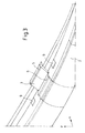
- FIG. 3 shows a view of the attachment 2 with the extension 3 on which a first latching step 5 and a second latching step 6 are arranged.
- the extension 3 is to be adapted to the openings 4 in the vehicle trim part 1 or vice versa, so that a locking in a Vorarrettechnik and a Endarretmaschine can be done.
- the extension 3 is preferably produced together with the attachment in a pressing process.
- the opening 4 in the vehicle trim part 1 must on the one hand enable insertion of the extension 3 as well as a locking in two latching steps 5, 6.
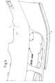
- Figure 4 shows a view of a vehicle trim part 1, here a bumper, with an attachment 2, here a spoiler, in the Vorarretisme, in which the attachment 2 is arranged at a distance from the vehicle trim part 1.
Landscapes
- Engineering & Computer Science (AREA)
- Mechanical Engineering (AREA)
- Connection Of Plates (AREA)
- Vehicle Interior And Exterior Ornaments, Soundproofing, And Insulation (AREA)
- Automobile Manufacture Line, Endless Track Vehicle, Trailer (AREA)
- Body Structure For Vehicles (AREA)
Abstract
Description
- Die Erfindung betrifft eine Anordnung nach dem Oberbegriff des Anspruches 1.
- Bauteile, die im End- oder Auslieferzustand miteinander verbaut sind, werden oft in getrennten Prozessschritten bearbeitet oder behandelt, obwohl die Prozessschritte sich gleichen, z. B. Lackieren eines Fahrzeugverkleidungsteils und eines Anbauteils getrennt voneinander. Dabei müssen unterschiedliche Vorrichtungen, z. B. Lackiergestelle, vorgehalten werden. Gerade beim Lackierprozess ist es schwierig, die Farbtonunterschiede zwischen in getrennten Prozessen lackierten Bauteilen, die im Endzustand miteinander verbaut sind, so gering wie möglich zu halten.
- In den Schutzrechten
DE 199 23 030 C2 ,DE 44 34 210 A1 oderJP 63-175666 A DE 199 23 030 C2 mit separaten Sicherungsklammern, beiDE 44 43 210 A1 mit länglichen Halte- und Rastelementen und beiJP 63-175666 A - Das Patent
EP 0 703 008 B1 beschreibt ein Verfahren, bei dem die Anbauteile vor dem Lackierprozess mit einem geringen Abstand zum Verkleidungsteil vorarretiert werden, nach dem Lackieren wieder für weitergehende Behandlungen demontiert und im anschließenden Montageprozess endgültig in die vorgesehene Endarretierung gebracht werden. - Die Prozesskette des fertigen Zusammenbaus ist teurer und aufwendiger bei getrennter Bearbeitung und Behandlung. Zum Beispiel ergibt sich zwangsläufig ein höherer Verbrauch des Behandlungsmediums (z. B. Primer, Lack) und ein höherer Bedarf an Montage- und Hilfsvorrichtungen. Auch die höheren Montagezeiten, als bei der Bearbeitung und Behandlung im Verbund, sind dabei oft die Kostentreiber.
- Der Erfindung liegt die Aufgabe zugrunde, eine Anordnung zur Bearbeitung und/oder Behandlung eines Fahrzeugverkleidungsteils zusammen mit einem Anbauteil nach dem Oberbegriff des Anspruchs 1 so zu verbessern, dass keine zusätzlichen Sicherungshilfsmittel zur Vorarretierung erforderlich sind und sowohl die Vor-, als auch die Endarretierung leicht und schnell zu bewerkstelligen sind.
- Erfindungsgemäß wird diese Aufgabe durch die Merkmale des Anspruchs 1 gelöst.
- Dadurch, dass die Befestigungsmittel als Schnappverbindung mit einer Vorarretierung und einer Endarretierung und einteilig mit dem Fahrzeugverkleidungsteil und/oder dem Anbauteil ausgebildet sind, ist eine Anordnung zur Bearbeitung und/oder Behandlung eines Fahrzeugverkleidungsteils zusammen mit einem Anbauteil so verbessert, dass keine zusätzlichen Teile erforderlich sind und die Vorarretierung und Endarretierung leicht und schnell zu bewerkstelligen ist.
- Es werden also anbauteilseitig Befestigungsmittel in Form einer Schnappverbindung mit einer Vorarretierung und einer Endarretierung, realisiert. Diese Befestigungselemente sind einteilig mit dem Anbauteil, bzw. dem Fahrzeugverkleidungsteil ausgeführt. Diese Ausführung ermöglicht eine einfache und schnelle Vor- und Endarretierung der jeweiligen Anbauteile sowie eine Lackierung von Stoßfängern und Anbauteilen in einem Prozessschritt, ohne die Verwendung zusätzlicher Sicherungshilfsmittel zur Vorarretierung.
- In einer bevorzugten Ausführungsform sind die Befestigungsmittel Erweiterungen (auch als Schnapphaken bezeichnet) an einem Teil, die in passende Öffnungen am anderen Teil einschnappbar sind und sind auf den Erweiterungen eine erste Raststufe zum Einschnappen in eine Vorarretierung und eine zweite Raststufe zum Einschnappen in die Endarretierung angeordnet.
An den Schnapphaken sind also auf der Oberseite eine erste Raststufe, zur Vorarretierung des Anbauteils, sowie eine zweite Raststufe zum Einschnappen in die Endarretierung vorgesehen. - Bevorzugt sind an der Unterseite der Erweiterungen (bzw. der Schnapphaken) im Bereich der ersten Raststufe Rippen angeordnet, auf denen die Erweiterung gleiten kann, so dass ein Einschieben in die Öffnungen am anderen Teil vereinfacht ist und diese Rippen ebenfalls der Fixierung im vorarretierten Zustand dienen.
- Dadurch kann der Schnapphaken einfach in die Öffnung am anderen Teil eingeführt werden. Durch die angeformten Rippen wird eine Auflagefläche geschaffen, die den Schnapphaken von der Unterseite in seiner vorverrasteten Position fixiert. Neben dem ersten Rastelement dienen also ebenfalls die angeformten Rippen der Vorarretierung des Anbauteils. Um ein unbeabsichtigtes Arretieren in der Endposition zu vermeiden ist bevorzugt an der Öffnung des Fahrzeugverkleidungsteils ein Hinterschnitt vorgesehen, der ein einfaches Einschieben des Anbauteils verhindert. Durch weitere seitliche Führungen an der Öffnung erfolgt eine genau Positionierung.
- Um eine Endarretierung zu realisieren sind neben den am Anbauteil vorgesehenen zweiten Rastelementen Abstimmungsrippen an der Öffnung des Fahrzeugverkleidungsteils angeordnet, die lediglich im endgültig verrasteten Zustand unter das Anbauteil greifen und dieses fixieren. Die Abstimmungsrippen sind am Fahrzeugverkleidungsteils vorgesehen und sind beidseitig neben den jeweiligen Öffnungen für die Schnapphaken angebracht.
- Vorteilhaft sind die Erweiterungen am Anbauteil und die Öffnungen im Fahrzeugverkleidungsteil angeordnet.
- Bevorzugt ist die Bearbeitung und/oder Behandlung ein Lackieren, mit allen vorgelagerten Bearbeitungsschritten (z. B. Powerwash oder Aktivierung der Oberfläche).
- In einer weiteren Ausgestaltung der Erfindung ist die Endarretierung mehrstufig ausgeführt. Hierdurch kann bei Bedarf eine Abstimmung oder eine Justierung der beiden Bauteile zueinander bei der Montage vorgenommen werden. Erfolgt die Befestigung über die beschriebenen Raststufen, so ist die zweite Raststufe mehrstufig ausgebildet.
- In einer Ausführungsform ist das Fahrzeugverkleidungsteil ein Stoßfänger und das Anbauteil ein aerodynamisches Bauteil, wie ein Spoiler, eine Spoilerblende, Radlaufverbreiterungen oder ein aerodynamischer Flügel.
- Die Erfindung zeichnet sich daher in einer bevorzugten Ausführungsform durch eine Vorarretierung des Aerodynamikbauteils am Fahrzeugverkleidungsteil, zum Beispiel einem Stoßfänger aus. In dieser Vorarretierung ist das Anbauteil mit Abstand zum Stoßfänger so angeordnet, dass eine problemlose Lackierung beider Teile möglich ist. Beim Lackieren durchlaufen beide Teile im vorarretierten Zustand die Lackieranlage. Anschließend, dies kann unmittelbar nach dem Lackieren oder auch später geschehen, wird das Aerodynamikbauteil von der Vorarretierung in die Endarretierung verschoben. Sowohl die Vorarretierung als auch die Endarretierung werden durch eine Schnappverbindung über eine erste und eine zweite Raststufe erreicht. Es werden keine weiteren Hilfsmittel bzw. Zusatzbauteile benötigt. Auch eine Demontage der gemeinsam lackierten Bauteile vor dem entgültigen Zusammenbau ist nicht erforderlich.
- Nachfolgend wird die Erfindung anhand von vier Figuren näher erläutert.
- Figur 1 zeigt in einem Schnitt ein Fahrzeugverkleidungsteil 1, hier ein Stoßfänger bzw. seine Außenhaut und ein Anbauteil 2, hier einen Spoiler oder eine Spoilerblende, in der Vorarretierung, bei der das Anbauteil 2 in Abstand vom Fahrzeugverkleidungsteil 1 angeordnet ist. In dieser Vorarretierung werden beide Teile gleichzeitig lackiert. Ein konstruktiv am Fahrzeugverkleidungsteil 1 vorgesehener Hinterschnitt 8 soll gewährleisten, dass das Anbauteil 2 nicht vor oder während der Lackierung unbeabsichtigt in den endgültig verrasteten Zustand geschoben wird.
- Diese Vorarretierung erfolgt über Befestigungsmittel, die als Schnappverbindung einteilig mit den Anbauteilen ausgebildet sind.
- Das Anbauteil weist hierzu Erweiterungen 3 auf, die in entsprechende Öffnungen 4 am Fahrzeugverkleidungsteil 1 eingeschoben werden. Auf der Erweiterung 3 sind eine erste Raststufe 5 zum Einschnappen in die Vorarretierung und eine zweite Raststufe 6 zum Einschnappen in die Endarretierung angeordnet.
- Figur 2 zeigt im selben Schnitt wie Figur 1 die Endarretierung des Anbauteils 2 am Fahrzeugverkleidungsteil 1. Die erste Raststufe 5 an der Erweiterung 3 ist in das Fahrzeugverkleidungsteil 1 eingeschoben worden und die zweite Raststufe 6, sowie am Fahrzeugverkleidungsteil 1vorgesehene Abstimmungsrippen 9 verankern das Anbauteil 2 in der Endarretierung. Um die Lage der Abstimmungsrippen 9 darzustellen sind diese ebenfalls in Figur 3 skizziert. In dieser Endarretierung kann das Fahrzeugverkleidungsteil 1 an den Kunden ausgeliefert bzw. am Fahrzeug montiert werden. Figur 2 zeigt auch sehr gut die an der Unterseite der ersten Raststufe angeordneten Rippen 7, über die die Erweiterung 3 des Anbauteils einfach in die Öffnung eingeführt werden kann und die ebenfalls der Fixierung des Anbauteils im vorverrasteten Zustand dienen.
- Figur 3 zeigt eine Ansicht des Anbauteils 2 mit der Erweiterung 3 auf der eine erste Raststufe 5 und eine zweite Raststufe 6 angeordnet sind. Die Erweiterung 3 ist an die Öffnungen 4 im Fahrzeugverkleidungsteil 1 anzupassen oder umgekehrt, so dass eine Verrastung in einer Vorarretierung und einer Endarretierung erfolgen kann.
- Die Erweiterung 3 ist bevorzugt zusammen mit dem Anbauteil in einem Pressvorgang hergestellt.
- Die Öffnung 4 im Fahrzeugverkleidungsteil 1 muss einerseits ein Einschieben der Erweiterung 3 als auch eine Verrastung in zwei Raststufen 5, 6 ermöglichen.
- Figur 4 zeigt eine Ansicht eines Fahrzeugverkleidungsteils 1, hier ein Stoßfänger, mit einem Anbauteil 2, hier ein Spoiler, in der Vorarretierung, bei der das Anbauteil 2 mit Abstand zum Fahrzeugverkleidungsteil 1 angeordnet ist.
- Durch die Vorarretierung ist das Anbauteil 2 mit Abstand zum Fahrzeugverkleidungsteil 1 angeordnet, so dass beim Lackieren auch die Kanten des Anbauteils 2 lackiert werden. Ein Lackierschatten ist dadurch verhindert.
Claims (9)
- Anordnung zur Bearbeitung und/oder Behandlung eines Fahrzeugverkleidungsteils (1) zusammen mit einem Anbauteil (2), bei welchem die Teile (1, 2) vor der Bearbeitung und/oder Behandlung einander zugeordnet und mittels Befestigungsmittel im Abstand voneinander vorarretiert sind und anschließend gemeinsam bearbeitbar und/oder behandelbar sind und nach der Bearbeitung und/oder Behandlung in Endstellung aneinander arretiert sind, dadurch gekennzeichnet, dass die Befestigungsmittel als Schnappverbindung mit einer Vorarretierung und einer Endarretierung und einteilig mit dem Fahrzeugverkleidungsteil (1) und/oder dem Anbauteil (2) ausgebildet sind.
- Anordnung nach Anspruch 1, dadurch gekennzeichnet, dass die Befestigungsmittel Erweiterungen (3) an einem Teil (1, 2) sind, die in passende Öffnungen (4) am anderen Teil (2, 1) einschnappbar sind und auf den Erweiterungen eine erste Raststufe (5) zum Einschnappen in die Vorarretierung und eine zweite Raststufe (6) zum Einschnappen in die Endarretierung angeordnet sind.
- Anordnung nach Anspruch 2, dadurch gekennzeichnet, dass an der Unterseite der Erweiterungen (3) im Bereich der ersten Raststufe (5) Rippen (7) angeordnet sind, auf denen die Erweiterung (3) gleiten kann, so dass ein Einschieben in die Öffnungen (4) am anderen Teil vereinfacht ist und diese Rippen (7) ebenfalls der Fixierung im vorarretierten Zustand dienen.
- Anordnung nach Anspruch 2 oder 3, dadurch gekennzeichnet, dass die Erweiterungen (3) am Anbauteil (2) und die Öffnungen (4) im Fahrzeugverkleidungsteil (1) angeordnet sind.
- Anordnung nach einem der Ansprüche 1 bis 4, dadurch gekennzeichnet, dass die Bearbeitung und/oder Behandlung ein Lackieren ist.
- Anordnung nach einem der Ansprüche 1 bis 5, dadurch gekennzeichnet, dass das Fahrzeugverkleidungsteil (1) ein Stoßfänger ist.
- Anordnung nach einem der Ansprüche 1 bis 6, dadurch gekennzeichnet, dass das Anbauteil (2) ein aerodynamisches Bauteil ist, wie ein Spoiler, eine Spoilerblende, Radlaufverbreiterungen oder ein aerodynamischer Flügel.
- Anordnung nach einem der Ansprüche 1 bis 7, dadurch gekennzeichnet, dass Abstimmungsrippen (9) an der Öffnung des Fahrzeugverkleidungsteils (1) angeordnet sind, die lediglich im endgültig verrasteten Zustand unter das Anbauteil (2) greifen und dieses fixieren.
- Anordnung nach einem der Ansprüche 1 bis 8, dadurch gekennzeichnet, dass die Endarretierung mehrstufig ausgeführt ist.
Applications Claiming Priority (1)
| Application Number | Priority Date | Filing Date | Title |
|---|---|---|---|
| DE102006050391A DE102006050391A1 (de) | 2006-10-20 | 2006-10-20 | Anordnung zur Befestigung und/oder Behandlung zweier Fahrzeugteile |
Publications (2)
| Publication Number | Publication Date |
|---|---|
| EP1914120A1 true EP1914120A1 (de) | 2008-04-23 |
| EP1914120B1 EP1914120B1 (de) | 2015-01-21 |
Family
ID=38969583
Family Applications (1)
| Application Number | Title | Priority Date | Filing Date |
|---|---|---|---|
| EP07118856.9A Not-in-force EP1914120B1 (de) | 2006-10-20 | 2007-10-19 | Anordnung zur Befestigung und/oder Behandlung zweier Fahrzeugteile |
Country Status (4)
| Country | Link |
|---|---|
| US (1) | US7891727B2 (de) |
| EP (1) | EP1914120B1 (de) |
| DE (1) | DE102006050391A1 (de) |
| ES (1) | ES2534896T3 (de) |
Cited By (4)
| Publication number | Priority date | Publication date | Assignee | Title |
|---|---|---|---|---|
| EP2669121A1 (de) * | 2012-05-30 | 2013-12-04 | Faurecia Exteriors GmbH | Karosseriebauteil und Verfahren zum Herstellen eines solchen |
| FR3059285A1 (fr) * | 2016-11-29 | 2018-06-01 | Peugeot Citroen Automobiles Sa | Elements d’habillage pour exterieur de vehicule automobile |
| DE102018206002A1 (de) * | 2018-04-19 | 2019-10-24 | Ford Global Technologies, Llc | Innenraum-Verkleidungsanordnung für einen Laderaum |
| FR3089481A1 (fr) * | 2018-12-07 | 2020-06-12 | Compagnie Plastic Omnium | Dispositif amélioré de fixation par clipsage |
Families Citing this family (6)
| Publication number | Priority date | Publication date | Assignee | Title |
|---|---|---|---|---|
| DE102010053302A1 (de) | 2010-12-02 | 2012-06-06 | Volkswagen Ag | Verbindungsanordnung zum lösbaren Verbinden zweier Bauteile und Verfahren zum Montieren zweier Bauteile |
| DE102011112514A1 (de) * | 2011-09-07 | 2013-03-07 | Apollo Vredestein B.V. | Luftleiteinrichtung eines Kraftfahrzeugs |
| KR20190069340A (ko) * | 2015-10-16 | 2019-06-19 | 꽁빠니에 쁠라스띠끄 옴니옴 | 자동차 범퍼 구조체 |
| JP6693401B2 (ja) * | 2016-12-08 | 2020-05-13 | トヨタ車体株式会社 | 車両用外装部品 |
| US10414365B2 (en) * | 2017-11-27 | 2019-09-17 | Toyota Motor Engineering & Manufacturing North America, Inc. | Bumper cover retainers including integral attachments that retain a bumper cover to the bumper cover retainer |
| DE102024122110B3 (de) * | 2024-08-02 | 2025-08-28 | Bayerische Motoren Werke Aktiengesellschaft | Stoßfängervorrichtung für ein Kraftfahrzeug |
Citations (5)
| Publication number | Priority date | Publication date | Assignee | Title |
|---|---|---|---|---|
| US3074134A (en) * | 1961-04-14 | 1963-01-22 | Thompson Ind Inc | Fastening means |
| DE19923030A1 (de) * | 1999-05-19 | 2000-11-30 | Peguform Gmbh | Stoßfängerhülle, Stoßleiste, Anordnung mit einer Stoßfängerhülle und einer Stoßleiste sowie Verfahren zur Lackierung einer Anordnung mit einer Stoßfängerhülle und mit einer Stoßleiste |
| DE10250392A1 (de) * | 2002-10-29 | 2004-05-19 | Decoma (Germany) Gmbh | Bauteil, insbesondere Stoßleiste, und System zu seiner Befestigung |
| EP1512582A1 (de) * | 2003-09-08 | 2005-03-09 | Compagnie Plastic Omnium | Band eingerastet in einem Karosserieteil eines Fahrzeuges |
| DE202005002907U1 (de) * | 2005-02-22 | 2005-06-02 | Peguform Gmbh | Befestigungsmechanismus |
Family Cites Families (4)
| Publication number | Priority date | Publication date | Assignee | Title |
|---|---|---|---|---|
| DE2718170C3 (de) * | 1977-04-23 | 1979-10-25 | Ford-Werke Ag, 5000 Koeln | Befestigungsclip für verkleidete Abdeckplatten, insbesondere für Kraftfahrzeuge |
| JPS63175666A (ja) * | 1987-01-14 | 1988-07-20 | Toyota Motor Corp | 樹脂部品の塗装方法 |
| DE9014254U1 (de) * | 1990-10-13 | 1990-12-20 | Camloc GmbH, 6233 Kelkheim | Vorrichtung zum lösbaren Verbinden zweier Bauteile |
| DE4434210A1 (de) * | 1994-09-24 | 1996-03-28 | Ymos Ag Ind Produkte | Verfahren zum Bearbeiten und/oder Behandeln eines mehrteiligen Gegenstandes sowie Halte- und Rastvorrichtung zur Durchführung des Verfahrens |
-
2006
- 2006-10-20 DE DE102006050391A patent/DE102006050391A1/de not_active Ceased
-
2007
- 2007-10-19 ES ES07118856.9T patent/ES2534896T3/es active Active
- 2007-10-19 EP EP07118856.9A patent/EP1914120B1/de not_active Not-in-force
- 2007-10-22 US US11/875,985 patent/US7891727B2/en active Active
Patent Citations (5)
| Publication number | Priority date | Publication date | Assignee | Title |
|---|---|---|---|---|
| US3074134A (en) * | 1961-04-14 | 1963-01-22 | Thompson Ind Inc | Fastening means |
| DE19923030A1 (de) * | 1999-05-19 | 2000-11-30 | Peguform Gmbh | Stoßfängerhülle, Stoßleiste, Anordnung mit einer Stoßfängerhülle und einer Stoßleiste sowie Verfahren zur Lackierung einer Anordnung mit einer Stoßfängerhülle und mit einer Stoßleiste |
| DE10250392A1 (de) * | 2002-10-29 | 2004-05-19 | Decoma (Germany) Gmbh | Bauteil, insbesondere Stoßleiste, und System zu seiner Befestigung |
| EP1512582A1 (de) * | 2003-09-08 | 2005-03-09 | Compagnie Plastic Omnium | Band eingerastet in einem Karosserieteil eines Fahrzeuges |
| DE202005002907U1 (de) * | 2005-02-22 | 2005-06-02 | Peguform Gmbh | Befestigungsmechanismus |
Cited By (5)
| Publication number | Priority date | Publication date | Assignee | Title |
|---|---|---|---|---|
| EP2669121A1 (de) * | 2012-05-30 | 2013-12-04 | Faurecia Exteriors GmbH | Karosseriebauteil und Verfahren zum Herstellen eines solchen |
| FR3059285A1 (fr) * | 2016-11-29 | 2018-06-01 | Peugeot Citroen Automobiles Sa | Elements d’habillage pour exterieur de vehicule automobile |
| DE102018206002A1 (de) * | 2018-04-19 | 2019-10-24 | Ford Global Technologies, Llc | Innenraum-Verkleidungsanordnung für einen Laderaum |
| US10875471B2 (en) | 2018-04-19 | 2020-12-29 | Ford Global Technologies, Llc | Interior cladding arrangement for a load space |
| FR3089481A1 (fr) * | 2018-12-07 | 2020-06-12 | Compagnie Plastic Omnium | Dispositif amélioré de fixation par clipsage |
Also Published As
| Publication number | Publication date |
|---|---|
| US20080100095A1 (en) | 2008-05-01 |
| DE102006050391A1 (de) | 2008-04-24 |
| US7891727B2 (en) | 2011-02-22 |
| EP1914120B1 (de) | 2015-01-21 |
| ES2534896T3 (es) | 2015-04-30 |
Similar Documents
| Publication | Publication Date | Title |
|---|---|---|
| EP1914120B1 (de) | Anordnung zur Befestigung und/oder Behandlung zweier Fahrzeugteile | |
| DE102014103796A1 (de) | System zur elastisch gemittelten Ausrichtung | |
| EP3650289A1 (de) | Lenkungsbaugruppe für eine fahrzeuglenkung | |
| EP1873016A1 (de) | Befestigungseinrichtung für ein Anbauteil | |
| EP2019765B1 (de) | Vorrichtung und verfahren zur befestigung eines wischermotors an ein wischergestänge | |
| DE4434210A1 (de) | Verfahren zum Bearbeiten und/oder Behandeln eines mehrteiligen Gegenstandes sowie Halte- und Rastvorrichtung zur Durchführung des Verfahrens | |
| DE102011018525A1 (de) | Verfahren und Vorrichtung zur Befestigung eines ersten Bauteils an einem zweiten Bauteil | |
| DE10250392B4 (de) | Bauteil, insbesondere Stoßleiste, und System zu seiner Befestigung | |
| DE112019004011T5 (de) | Montagesystem für ein Kastenprofil | |
| DE102012110652A1 (de) | Vorrichtung zur Fugeneinstellung zwischen Anbauteilen | |
| DE102009020549B4 (de) | Vorrichtung und Verfahren zur Montage eines Modulträgers in ein Fahrzeug | |
| DE102017107762A1 (de) | Lenkrad für ein kraftfahrzeug | |
| EP1213186A2 (de) | Vorrichtung zum Befestigen von zwei Bauteilen | |
| EP1693252B1 (de) | Befestigungsmechanismus | |
| DE102019104767A1 (de) | Montageanordnung, Verwendung einer Montagevorrichtung sowie Montageverfahren | |
| DE29616891U1 (de) | Einrichtung zum Befestigen eines Gassackmoduls | |
| DE102022118397A1 (de) | Anordnung zum bereitstellen einer befestigungsmöglichkeit für eine fahrzeugkomponente | |
| DE102012023785A1 (de) | Vorrichtung zum spannungsarmen Verbinden zweier Bauteile eines Kraftfahrzeuges sowie Fahrzeug-Scheinwerfer | |
| WO2022023534A1 (de) | Dachhaubenteil einer führerkabine eines lastkraftfahrzeugs, führerkabine eines lastkraftfahrzeugs und verfahren zum befestigen eines gehäuses eines funktionsteils, insbesondere einer leuchte an einem grundkörper eines dachhaubenteils | |
| DE102009058815A1 (de) | Haltevorrichtung für Anbauteile, insbesondere für Sonnenblenden, von Fahrzeugen | |
| DE102007002214A1 (de) | Vorrichtung zur Abstützung eines Stoßfängerüberzugs eines Stoßfängers | |
| DE102019008731A1 (de) | Schraubanordnung | |
| EP4012204B1 (de) | Befestigungsanordnung und verwendung einer befestigungsanordnung | |
| DE102005041216A1 (de) | Befestigungsanordnung von Außenbeplankungsteilen eines Kraftwagens | |
| EP3587217A1 (de) | Befestigungssystem für abdeckungsbauteile eines lenkrads, lenkrad sowie verfahren zur herstellung eines lenkrads |
Legal Events
| Date | Code | Title | Description |
|---|---|---|---|
| PUAI | Public reference made under article 153(3) epc to a published international application that has entered the european phase |
Free format text: ORIGINAL CODE: 0009012 |
|
| 17P | Request for examination filed |
Effective date: 20071019 |
|
| AK | Designated contracting states |
Kind code of ref document: A1 Designated state(s): AT BE BG CH CY CZ DE DK EE ES FI FR GB GR HU IE IS IT LI LT LU LV MC MT NL PL PT RO SE SI SK TR |
|
| AX | Request for extension of the european patent |
Extension state: AL BA HR MK RS |
|
| 17Q | First examination report despatched |
Effective date: 20080704 |
|
| AKX | Designation fees paid |
Designated state(s): AT BE BG CH CY CZ DE DK EE ES FI FR GB GR HU IE IS IT LI LT LU LV MC MT NL PL PT RO SE SI SK TR |
|
| RAP1 | Party data changed (applicant data changed or rights of an application transferred) |
Owner name: DR.ING. H.C. F. PORSCHE AKTIENGESELLSCHAFT Owner name: FAURECIA EXTERIORS GMBH |
|
| GRAP | Despatch of communication of intention to grant a patent |
Free format text: ORIGINAL CODE: EPIDOSNIGR1 |
|
| INTG | Intention to grant announced |
Effective date: 20140807 |
|
| GRAS | Grant fee paid |
Free format text: ORIGINAL CODE: EPIDOSNIGR3 |
|
| GRAA | (expected) grant |
Free format text: ORIGINAL CODE: 0009210 |
|
| RAP1 | Party data changed (applicant data changed or rights of an application transferred) |
Owner name: FAURECIA EXTERIORS GMBH Owner name: DR.ING. H.C. F. PORSCHE AKTIENGESELLSCHAFT |
|
| AK | Designated contracting states |
Kind code of ref document: B1 Designated state(s): AT BE BG CH CY CZ DE DK EE ES FI FR GB GR HU IE IS IT LI LT LU LV MC MT NL PL PT RO SE SI SK TR |
|
| REG | Reference to a national code |
Ref country code: GB Ref legal event code: FG4D Free format text: NOT ENGLISH |
|
| REG | Reference to a national code |
Ref country code: CH Ref legal event code: EP |
|
| REG | Reference to a national code |
Ref country code: IE Ref legal event code: FG4D Free format text: LANGUAGE OF EP DOCUMENT: GERMAN |
|
| REG | Reference to a national code |
Ref country code: AT Ref legal event code: REF Ref document number: 707664 Country of ref document: AT Kind code of ref document: T Effective date: 20150215 |
|
| REG | Reference to a national code |
Ref country code: DE Ref legal event code: R096 Ref document number: 502007013691 Country of ref document: DE Effective date: 20150305 |
|
| REG | Reference to a national code |
Ref country code: ES Ref legal event code: FG2A Ref document number: 2534896 Country of ref document: ES Kind code of ref document: T3 Effective date: 20150430 |
|
| REG | Reference to a national code |
Ref country code: NL Ref legal event code: VDEP Effective date: 20150121 |
|
| REG | Reference to a national code |
Ref country code: LT Ref legal event code: MG4D |
|
| PG25 | Lapsed in a contracting state [announced via postgrant information from national office to epo] |
Ref country code: FI Free format text: LAPSE BECAUSE OF FAILURE TO SUBMIT A TRANSLATION OF THE DESCRIPTION OR TO PAY THE FEE WITHIN THE PRESCRIBED TIME-LIMIT Effective date: 20150121 Ref country code: SE Free format text: LAPSE BECAUSE OF FAILURE TO SUBMIT A TRANSLATION OF THE DESCRIPTION OR TO PAY THE FEE WITHIN THE PRESCRIBED TIME-LIMIT Effective date: 20150121 Ref country code: LT Free format text: LAPSE BECAUSE OF FAILURE TO SUBMIT A TRANSLATION OF THE DESCRIPTION OR TO PAY THE FEE WITHIN THE PRESCRIBED TIME-LIMIT Effective date: 20150121 Ref country code: BG Free format text: LAPSE BECAUSE OF FAILURE TO SUBMIT A TRANSLATION OF THE DESCRIPTION OR TO PAY THE FEE WITHIN THE PRESCRIBED TIME-LIMIT Effective date: 20150421 |
|
| PG25 | Lapsed in a contracting state [announced via postgrant information from national office to epo] |
Ref country code: IS Free format text: LAPSE BECAUSE OF FAILURE TO SUBMIT A TRANSLATION OF THE DESCRIPTION OR TO PAY THE FEE WITHIN THE PRESCRIBED TIME-LIMIT Effective date: 20150521 Ref country code: NL Free format text: LAPSE BECAUSE OF FAILURE TO SUBMIT A TRANSLATION OF THE DESCRIPTION OR TO PAY THE FEE WITHIN THE PRESCRIBED TIME-LIMIT Effective date: 20150121 Ref country code: GR Free format text: LAPSE BECAUSE OF FAILURE TO SUBMIT A TRANSLATION OF THE DESCRIPTION OR TO PAY THE FEE WITHIN THE PRESCRIBED TIME-LIMIT Effective date: 20150422 Ref country code: LV Free format text: LAPSE BECAUSE OF FAILURE TO SUBMIT A TRANSLATION OF THE DESCRIPTION OR TO PAY THE FEE WITHIN THE PRESCRIBED TIME-LIMIT Effective date: 20150121 Ref country code: PL Free format text: LAPSE BECAUSE OF FAILURE TO SUBMIT A TRANSLATION OF THE DESCRIPTION OR TO PAY THE FEE WITHIN THE PRESCRIBED TIME-LIMIT Effective date: 20150121 |
|
| REG | Reference to a national code |
Ref country code: DE Ref legal event code: R097 Ref document number: 502007013691 Country of ref document: DE |
|
| PG25 | Lapsed in a contracting state [announced via postgrant information from national office to epo] |
Ref country code: SK Free format text: LAPSE BECAUSE OF FAILURE TO SUBMIT A TRANSLATION OF THE DESCRIPTION OR TO PAY THE FEE WITHIN THE PRESCRIBED TIME-LIMIT Effective date: 20150121 Ref country code: RO Free format text: LAPSE BECAUSE OF FAILURE TO SUBMIT A TRANSLATION OF THE DESCRIPTION OR TO PAY THE FEE WITHIN THE PRESCRIBED TIME-LIMIT Effective date: 20150121 Ref country code: DK Free format text: LAPSE BECAUSE OF FAILURE TO SUBMIT A TRANSLATION OF THE DESCRIPTION OR TO PAY THE FEE WITHIN THE PRESCRIBED TIME-LIMIT Effective date: 20150121 Ref country code: EE Free format text: LAPSE BECAUSE OF FAILURE TO SUBMIT A TRANSLATION OF THE DESCRIPTION OR TO PAY THE FEE WITHIN THE PRESCRIBED TIME-LIMIT Effective date: 20150121 Ref country code: CZ Free format text: LAPSE BECAUSE OF FAILURE TO SUBMIT A TRANSLATION OF THE DESCRIPTION OR TO PAY THE FEE WITHIN THE PRESCRIBED TIME-LIMIT Effective date: 20150121 |
|
| PLBE | No opposition filed within time limit |
Free format text: ORIGINAL CODE: 0009261 |
|
| STAA | Information on the status of an ep patent application or granted ep patent |
Free format text: STATUS: NO OPPOSITION FILED WITHIN TIME LIMIT |
|
| 26N | No opposition filed |
Effective date: 20151022 |
|
| PG25 | Lapsed in a contracting state [announced via postgrant information from national office to epo] |
Ref country code: SI Free format text: LAPSE BECAUSE OF FAILURE TO SUBMIT A TRANSLATION OF THE DESCRIPTION OR TO PAY THE FEE WITHIN THE PRESCRIBED TIME-LIMIT Effective date: 20150121 |
|
| PG25 | Lapsed in a contracting state [announced via postgrant information from national office to epo] |
Ref country code: LU Free format text: LAPSE BECAUSE OF FAILURE TO SUBMIT A TRANSLATION OF THE DESCRIPTION OR TO PAY THE FEE WITHIN THE PRESCRIBED TIME-LIMIT Effective date: 20151019 |
|
| REG | Reference to a national code |
Ref country code: CH Ref legal event code: PL |
|
| PG25 | Lapsed in a contracting state [announced via postgrant information from national office to epo] |
Ref country code: MC Free format text: LAPSE BECAUSE OF FAILURE TO SUBMIT A TRANSLATION OF THE DESCRIPTION OR TO PAY THE FEE WITHIN THE PRESCRIBED TIME-LIMIT Effective date: 20150121 |
|
| REG | Reference to a national code |
Ref country code: IE Ref legal event code: MM4A |
|
| PG25 | Lapsed in a contracting state [announced via postgrant information from national office to epo] |
Ref country code: CH Free format text: LAPSE BECAUSE OF NON-PAYMENT OF DUE FEES Effective date: 20151031 Ref country code: LI Free format text: LAPSE BECAUSE OF NON-PAYMENT OF DUE FEES Effective date: 20151031 |
|
| REG | Reference to a national code |
Ref country code: FR Ref legal event code: PLFP Year of fee payment: 10 |
|
| PG25 | Lapsed in a contracting state [announced via postgrant information from national office to epo] |
Ref country code: IE Free format text: LAPSE BECAUSE OF NON-PAYMENT OF DUE FEES Effective date: 20151019 |
|
| REG | Reference to a national code |
Ref country code: AT Ref legal event code: MM01 Ref document number: 707664 Country of ref document: AT Kind code of ref document: T Effective date: 20151019 |
|
| PG25 | Lapsed in a contracting state [announced via postgrant information from national office to epo] |
Ref country code: AT Free format text: LAPSE BECAUSE OF NON-PAYMENT OF DUE FEES Effective date: 20151019 |
|
| PG25 | Lapsed in a contracting state [announced via postgrant information from national office to epo] |
Ref country code: HU Free format text: LAPSE BECAUSE OF FAILURE TO SUBMIT A TRANSLATION OF THE DESCRIPTION OR TO PAY THE FEE WITHIN THE PRESCRIBED TIME-LIMIT; INVALID AB INITIO Effective date: 20071019 |
|
| PG25 | Lapsed in a contracting state [announced via postgrant information from national office to epo] |
Ref country code: CY Free format text: LAPSE BECAUSE OF FAILURE TO SUBMIT A TRANSLATION OF THE DESCRIPTION OR TO PAY THE FEE WITHIN THE PRESCRIBED TIME-LIMIT Effective date: 20150121 |
|
| PG25 | Lapsed in a contracting state [announced via postgrant information from national office to epo] |
Ref country code: BE Free format text: LAPSE BECAUSE OF NON-PAYMENT OF DUE FEES Effective date: 20151031 |
|
| PG25 | Lapsed in a contracting state [announced via postgrant information from national office to epo] |
Ref country code: MT Free format text: LAPSE BECAUSE OF FAILURE TO SUBMIT A TRANSLATION OF THE DESCRIPTION OR TO PAY THE FEE WITHIN THE PRESCRIBED TIME-LIMIT Effective date: 20150121 Ref country code: TR Free format text: LAPSE BECAUSE OF FAILURE TO SUBMIT A TRANSLATION OF THE DESCRIPTION OR TO PAY THE FEE WITHIN THE PRESCRIBED TIME-LIMIT Effective date: 20150121 |
|
| REG | Reference to a national code |
Ref country code: FR Ref legal event code: PLFP Year of fee payment: 11 |
|
| REG | Reference to a national code |
Ref country code: DE Ref legal event code: R082 Ref document number: 502007013691 Country of ref document: DE Representative=s name: STUMPF PATENTANWAELTE PARTGMBB, DE Ref country code: DE Ref legal event code: R082 Ref document number: 502007013691 Country of ref document: DE Representative=s name: SPRANGER, STEPHAN, DIPL.-PHYS.UNIV., DE Ref country code: DE Ref legal event code: R081 Ref document number: 502007013691 Country of ref document: DE Owner name: DR. ING. H.C. F. PORSCHE AKTIENGESELLSCHAFT, DE Free format text: FORMER OWNERS: DR. ING. H.C. F. PORSCHE AKTIENGESELLSCHAFT, 70435 STUTTGART, DE; FAURECIA EXTERIORS GMBH, 31655 STADTHAGEN, DE Ref country code: DE Ref legal event code: R081 Ref document number: 502007013691 Country of ref document: DE Owner name: PLASTIC OMNIUM AUTOMOTIVE EXTERIORS GMBH, DE Free format text: FORMER OWNERS: DR. ING. H.C. F. PORSCHE AKTIENGESELLSCHAFT, 70435 STUTTGART, DE; FAURECIA EXTERIORS GMBH, 31655 STADTHAGEN, DE |
|
| PG25 | Lapsed in a contracting state [announced via postgrant information from national office to epo] |
Ref country code: PT Free format text: LAPSE BECAUSE OF FAILURE TO SUBMIT A TRANSLATION OF THE DESCRIPTION OR TO PAY THE FEE WITHIN THE PRESCRIBED TIME-LIMIT Effective date: 20150121 |
|
| REG | Reference to a national code |
Ref country code: FR Ref legal event code: PLFP Year of fee payment: 12 |
|
| PGFP | Annual fee paid to national office [announced via postgrant information from national office to epo] |
Ref country code: CH Payment date: 20181115 Year of fee payment: 6 |
|
| PGFP | Annual fee paid to national office [announced via postgrant information from national office to epo] |
Ref country code: GB Payment date: 20180925 Year of fee payment: 12 |
|
| PGFP | Annual fee paid to national office [announced via postgrant information from national office to epo] |
Ref country code: ES Payment date: 20181105 Year of fee payment: 12 |
|
| REG | Reference to a national code |
Ref country code: DE Ref legal event code: R082 Ref document number: 502007013691 Country of ref document: DE Representative=s name: STUMPF PATENTANWAELTE PARTGMBB, DE |
|
| PGFP | Annual fee paid to national office [announced via postgrant information from national office to epo] |
Ref country code: DE Payment date: 20191030 Year of fee payment: 13 |
|
| PGFP | Annual fee paid to national office [announced via postgrant information from national office to epo] |
Ref country code: FR Payment date: 20191030 Year of fee payment: 13 |
|
| GBPC | Gb: european patent ceased through non-payment of renewal fee |
Effective date: 20191019 |
|
| PG25 | Lapsed in a contracting state [announced via postgrant information from national office to epo] |
Ref country code: IT Free format text: LAPSE BECAUSE OF NON-PAYMENT OF DUE FEES Effective date: 20191019 Ref country code: GB Free format text: LAPSE BECAUSE OF NON-PAYMENT OF DUE FEES Effective date: 20191019 |
|
| REG | Reference to a national code |
Ref country code: DE Ref legal event code: R119 Ref document number: 502007013691 Country of ref document: DE |
|
| PG25 | Lapsed in a contracting state [announced via postgrant information from national office to epo] |
Ref country code: FR Free format text: LAPSE BECAUSE OF NON-PAYMENT OF DUE FEES Effective date: 20201031 Ref country code: DE Free format text: LAPSE BECAUSE OF NON-PAYMENT OF DUE FEES Effective date: 20210501 |
|
| PG25 | Lapsed in a contracting state [announced via postgrant information from national office to epo] |
Ref country code: ES Free format text: LAPSE BECAUSE OF NON-PAYMENT OF DUE FEES Effective date: 20191020 |
|
| P01 | Opt-out of the competence of the unified patent court (upc) registered |
Effective date: 20230526 |