EP1908726B1 - Isobare Rotationsfüllmaschine zur Füllung von Containern mit Flüssigkeiten - Google Patents
Isobare Rotationsfüllmaschine zur Füllung von Containern mit Flüssigkeiten Download PDFInfo
- Publication number
- EP1908726B1 EP1908726B1 EP07112098A EP07112098A EP1908726B1 EP 1908726 B1 EP1908726 B1 EP 1908726B1 EP 07112098 A EP07112098 A EP 07112098A EP 07112098 A EP07112098 A EP 07112098A EP 1908726 B1 EP1908726 B1 EP 1908726B1
- Authority
- EP
- European Patent Office
- Prior art keywords
- flushing
- receiving tray
- valve units
- valve
- circuit
- Prior art date
- Legal status (The legal status is an assumption and is not a legal conclusion. Google has not performed a legal analysis and makes no representation as to the accuracy of the status listed.)
- Active
Links
Images


Classifications
-
- B—PERFORMING OPERATIONS; TRANSPORTING
- B67—OPENING, CLOSING OR CLEANING BOTTLES, JARS OR SIMILAR CONTAINERS; LIQUID HANDLING
- B67C—CLEANING, FILLING WITH LIQUIDS OR SEMILIQUIDS, OR EMPTYING, OF BOTTLES, JARS, CANS, CASKS, BARRELS, OR SIMILAR CONTAINERS, NOT OTHERWISE PROVIDED FOR; FUNNELS
- B67C3/00—Bottling liquids or semiliquids; Filling jars or cans with liquids or semiliquids using bottling or like apparatus; Filling casks or barrels with liquids or semiliquids
- B67C3/001—Cleaning of filling devices
-
- B—PERFORMING OPERATIONS; TRANSPORTING
- B08—CLEANING
- B08B—CLEANING IN GENERAL; PREVENTION OF FOULING IN GENERAL
- B08B3/00—Cleaning by methods involving the use or presence of liquid or steam
- B08B3/02—Cleaning by the force of jets or sprays
Definitions
- the present invention relates to an isobaric rotary filling machine for filling containers with liquids.
- the machine in question is intended to be used in the bottling industry for filling containers, in particular bottles, with gaseous liquids, i.e. liquids containing carbon dioxide, for example gaseous beverages such as fizzy wine, mineral water, beer, etc.
- gaseous liquids i.e. liquids containing carbon dioxide
- gaseous beverages such as fizzy wine, mineral water, beer, etc.
- the machine is provided with a rotating table or carousel having, peripherally mounted thereon, a plurality of valve units for filling the containers which are positioned underneath during their travel from the entry point to the outlet of the machine.
- the machine is also provided with a tank for storing the liquid to be bottled, which is kept at a pressure higher than atmospheric pressure and is connected to a supply line able to replenish it with the liquid which is transferred to the valve units for filling the containers.
- Each valve unit has an obturator or faucet which regulates the flow of the liquid into the container, usually a glass or PET bottle, when the latter is arranged coaxially underneath the valve unit.
- the obturator is mounted inside a tubular duct of the valve unit which connects the liquid storage tank to the containers. Bottling with isobaric filling machines allows the liquid to be introduced into the container while keeping its pressure unchanged.
- the valve unit also has an air return pipe which is mounted inside the duct and balances the pressure inside the container also during descent of the liquid.
- the bottom part of this pipe also normally has the function of adjusting, for example hydraulically or by means of a probe, the maximum level of the liquid inside the container, upon reaching of which the flow of the liquid to the container must be interrupted hydraulically by closing the obturator.
- a first reason consists in the fact that cleaning of all the machine parts, and in particular the valve units, which come into contact with the liquid to be bottled, must be performed periodically in order to keep the bacterial content as low as possible.
- Stoppage may be envisaged, for example, for maintenance of the machine or for a temporary interruption in the working activity.
- a second reason consists in the need to change the bottling product and therefore clean the machine in order to avoid contamination between different liquids.
- all the product from the previous production cycle must be discharged before starting a new cycle.
- the product change-over is frequently carried out by discharging the previous liquid still present in the valve units directly onto the bottle support discs and onto other mechanical parts of the machine, resulting in general soiling which reduces the working life of the machine and also prevents the observance of proper hygienic conditions.
- the flushing operations require circulation of a flushing fluid (mostly consisting of suitable aqueous solutions) inside all the pipes where the liquid passes and where the air or inert gas passes.
- a flushing fluid mostly consisting of suitable aqueous solutions
- auxiliary containers - referred in the technical jargon of the sector as "dummy bottles" - which allow opening of the individual valve units and execution of a closed cycle by means of which the flushing fluid is circulated.
- auxiliary containers are mounted, for this purpose, underneath each valve unit so as to be able to open the obturators and allow the recirculation of the flushing fluid inside a closed circuit which supplies the duct of the valve units and the air return pipe.
- This flushing system of the known type involves long manual operations in order to mount the auxiliary containers on each valve unit and does not allow automatic programming for carrying out the flushing cycles.
- Opening of the faucets in order to discharge the liquid is performed on most occasions manually and therefore requires the use of an operator, resulting in considerable amount of lost time and expense.
- the document EP 0568121 describes a device comprising means for supplying a wash liquor to a filling liquid tank and collection means for collecting through the nozzle the wash liquor supplied to the tank.
- the collection means comprise a liquid receptacle connectable to the discharge end of the nozzle and removably connected to a collection pipe secured to the rotating table.
- This flushing system of the known type presents various disadvantages as well.
- the device is in fact constructionally complex since it is necessary to provide each nozzle or couple of nozzles with said collection means, resulting also in a rise in costs. Furthermore, long time are required in order to prepare the device for cleaning: for each couple of nozzle, the collection means need indeed to be set and connected to the collection pipe, with a consequent waste of time.
- the problem underlying the present invention is therefore to overcome the drawbacks of the machines of the known type by providing an isobaric rotary filling machine which allows the automatic flushing of all its parts to be performed easily and in a cost-effective manner.
- a further object of the present invention is to provide a machine which is constructionally simple and operationally entirely reliable and does not involve free discharging of the flushing liquid left inside each valve unit in order to perform flushing.
- a further object of the present invention is to provide a machine which allows the bottling product to be changed rapidly and automatically, without free discharging of the liquid from the previous bottling cycle.
- Another object of the machine in question to provide a machine, the valve units of which are able to initiate filling of the containers without sudden start-ups.
- 1 denotes in it entirety the isobaric rotary filling machine according to the present invention. It is intended to perform the bottling of containers with gaseous fluids, which are generally used in the food industry, such as, for example, beverages containing carbon dioxide, sparkling wines, beer, mineral water or the like.
- the machine 1 may be incorporated, in an entirely conventional manner, within a bottling plant or line equipped with several machines which work in series and in particular are provided upstream with a rinsing machine and downstream with a corking or capping machine, between which the bottles are transferred by means of conveying lines, such as, for example, conveyor belts, starwheels with compartments, feeder screws or the like.
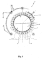
- the machine 1 comprises essentially a support structure 100 resting on the ground and able to support rotatably a rotating table 2 provided peripherally with a plurality of valve units 3 (filling heads) for transferring a gaseous liquid to be bottled from a tank 6 under pressure to underlying containers to be filled (not shown) which generally consist of glass or PET bottles.
- a support structure 100 resting on the ground and able to support rotatably a rotating table 2 provided peripherally with a plurality of valve units 3 (filling heads) for transferring a gaseous liquid to be bottled from a tank 6 under pressure to underlying containers to be filled (not shown) which generally consist of glass or PET bottles.
- the latter are conveyed around the machine 1, in a manner conventional per se, by a plurality of discs 7 rotating in synchronism with the valve units 3 and able to transfer the containers from an entry starwheel 9 to an exit starwheel 10.
- the tank 6 is connected to a supply line 31 which has, connected along it, a valve 30 and by a pump 17 for replenishing the tank 6 with the liquid which is then transferred to the valve units 3 for filling the containers.
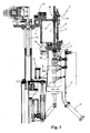
- Each valve unit 3 has a filling duct 4 associated with first shut-off means 5 consisting of a faucet with the obturator controlled so as to open and close by means of a pneumatic obturator.
- the faucets 5 regulate the flow of the liquid from the tank 6 to the container, which rotates in synchronism with the valve unit 3 supported by the disc 7.
- Each valve unit 3 also has a pipe 8 for the return flow of the air and for pressuring the bottle, which is mounted concentrically with the duct 4, being associated in turn with second shut-off means 60 for controlling the pressure balance between the container and the tank 6.
- These second shut-off means 60 preferably consist of a pneumatic valve.
- the air return pipe 8 has a terminal section which is intended to be inserted inside the mouth of the container and is usually used in order to adjust the maximum level of liquid inside the container.
- adjustment of this level may be achieved by varying mechanically the height of the pipe 8 by adjusting means 90 for the pipe 8, which are associated with its top end, as in the case envisaged in the accompanying figures.
- the pipe 8 upon arrival of the liquid, will cause the hydraulic closure of the air return passage.
- a Teflon sealing bellows 61 is also envisaged for allowing adjustable sliding of the pipe following activation of the adjusting means 90 while maintaining the sealing effect on the tank 6.
- adjustment may be obtained by means of a pipe 8 provided with an electric probe which can be adjusted heightwise and is able to sense when the liquid reaches the required level and therefore control, in an adjustable manner, the delay in closing of the first shut-off means 5 and the second shut-off means 60.
- the level may be achieved by replacing the terminal part of the pipe depending on the form of the container and the required liquid level.
- Each valve unit 3 also has a centring cone 101 against which the discs 7 bring the mouth of the containers into sealing contact.
- the working height of the rotating table 2 or the tank 6 and the valve units 3 is adjusted by means of first raising means 13 so as to take into account, for example, the height of the containers.
- These raising means 13 are preferably formed by a linear actuator of the mechanical type which is mounted in the central shaft for supporting and rotating the rotating table 2.
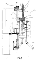
- the machine 1 comprises a flushing station 14 which is situated laterally on the side of the machine 1, along a section thereof, and is operationally associated with the rotating table 2 but is fixed with respect thereto.
- the abovementioned station 14 is provided with a receiving tray 15 which can be operated by movement means 16 so as to move between a non-operative position A (see Figure 5 ), where it is situated outside the travel path of the valve unit 3, and an operative position B (see Figure 6 ), where it is situated underneath one or more valve units 3 able to pass above it.
- the receiving tray 15 may extend, preferably with a curved form, so as to embrace one or more valve units 3.
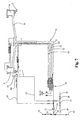
- the abovementioned flushing station 14 comprises a flushing circuit C, shown by way of example in Figure 7 , which is connected to the supply line 31 of the tank 6 via third shut-off means 32 consisting preferably also of a valve.
- the abovementioned flushing station 14 will be operationally used both for the flushing operations and also, as indicated further below, for performing change-over of the product to be bottled.
- the machine 1 activates the circuit C so as to convey the flushing fluid to the supply line 31 of the tank 6, for this purpose the valve 32 being open and the valve 30 closed.
- the first and second shut-off means 5 and 60 are correspondingly open in order to allow the flushing fluid to flow into the filling ducts and into the pipes 8 of the valve units 3, situated above the receiving tray 15, so as to cause the fluid to fall into the underlying receiving tray 15 and the flushing fluid to circulate inside the flushing circuit C.
- Circulation of the flushing fluid is obtained, in accordance with the diagram shown in Figure 7 , by the same pump 17 for the liquid to be bottled, which therefore also undergoes flushing.
- the delivery circuit 31, which is used in order to convey the flushing fluid, is provided with branch-offs for causing the said fluid to flow also in all the operating circuits which must be flushed, the first of which being the filling duct 4 and the air return pipe 8 of each valve unit 3.
- the same circuit C therefore has a return pipe 19 which removes the fluid by means of a connection provided on the bottom of the receiving tray 15 so as to direct it conveniently again into a closed circuit by means of the branch 35.
- the station 14 with the circuit C and the tank 15 may also perform the different function of product change-over.
- valve units 3 it is possible to envisage causing all the valve units 3 to pass above the receiving tray 15 in order to discharge the liquid contained inside them by means of simple opening of the shut-off means 5, 60 of the filling ducts 4 and the air return pipes 8.
- the pump 17 will be switched off and the valve 30 and the shut-off means 32 will be closed in order to supply the line 31 with the product to be bottled or with the flushing liquid, respectively.
- the return line 19 will allow via the branch 36 collection of the product used in the previous bottling operations. Selection of the branch 35 and 36 for recycling the flushing product or for collecting the liquid to be bottled will be performed by means of control of the valves 37 and 38.
- the machine will allow, by means of its flushing station 14, the cleaning of numerous operating circuits which may have been soiled during operation of the machine 1.
- these operating circuits may comprise: a gas-release circuit 20 connected to each valve unit 3 for ensuring that the container is under atmospheric pressure again once filling has been completed; a self-levelling circuit 21 for correcting the liquid level inside the containers by means of the introduction of inert gas; a pre-evacuation circuit 22 for drawing the air from said containers before the introduction of said liquid with a vacuum pump; a back-pressure circuit 23 for keeping said tank 6 at a desired overpressure with inert gas.
- Each of these operating circuits 20-23 is provided with its own shut-off means - indicated overall for the sake of simplicity as fourth shut-off means 24 - which, like the previous means, are controlled by the logic control unit of the machine 1 for correct operation thereof in accordance with predefined operating steps.
- the gas-release circuit has in the conventional applications of the known type the free end which discharges into the air via a calibrated valve able to reset gradually the pressure inside the bottles to atmospheric pressure.
- such a circuit 20 is now channelled to the tank 6 so that it may be backwashed during the flushing operations.
- shut-off means 24 consist of a central distributor and corresponding electro-pneumatic valves which can be operated so as to open and close by a fluid under pressure and are denoted overall by 24 in the accompanying figures.
- the flushing circuit C is connected by means of valves 25 to the abovementioned operating circuits 20-23 as indicated schematically in Figure 7 .
- the fluid conveyed in the operating circuits is always directed to the valve units 3 or to the tank 6 so as to cause it flow always inside the receiving tray 15 and allow recycling of the flushing product by means of the return line 19.
- flushing of the gas-release circuit 20, the self-levelling circuit 21 and the pre-evacuation circuit 22 is performed in the opposite direction to the normal flow of gas or liquid inside these circuits, resulting in better and more complete cleaning of the shut-off valves 24.
- the flushing circuit C has a line 39 connected to a plurality of nozzles 40 mounted on the receiving tray 15 as is clearly shown in the accompanying figures.
- nozzles 40 are able to wash externally with jets 41 of flushing fluid each valve unit 3 when the latter is arranged opposite the receiving tray 15 during a flushing operation.
- the nozzles 40 may be movably directed in order to wash better the valve units 3 during spraying of the flushing liquid.
- Figures 5 and 6 show the receiving tray in the two different positions, i.e. a non-operative position A and operative position B, which are assumed by means of activation of the movement means advantageously consisting of a linear actuator of the pneumatic type.
- the receiving tray 15 is clearly illustrated in the example of embodiment shown in Figure 4 where 42 denotes the outer wall on which the nozzles 40 are preferably arranged in several rows at different heights and 43 denotes the inner wall which extends vertically over a height less than that of the outer wall so as to allow easy engagement thereof behind the valve unit 3.
- the outer wall 42 and inner wall 43 of the tray 15 are arc-shaped so as to follow the progression of the rotating table 2 of the valve units 3.
- the receiving tray 15 may extend over an arc having a length such as to embrace several valve units 3 and preferably three valve units 3.
- the receiving tray 15 also has a front wall 44 and a real wall 45 which are provided with large openings 46 for allowing the valve units 3 to pass over the receiving tray 15 when the latter is in the operative position B.
- the isobaric rotating filling machine 1 described hitherto is suitable for being used for bottling both plastic containers and glass containers.
- separator cowls 46 fixed to the rotating table 2 on the sides of each valve unit 3 are usually envisaged.
- isobaric rotary filling machines 1 work with the tank 6 under pressure and therefore subject the containers to a pressures which, in the event of malfunctions or defects, may cause them to break.
- These separator cowls 46 consist of plates which are generally made of metal and are able to protect the machine 1 and the operators from any glass which may be projected into the air by the sudden breakage of bottles which are not perfectly manufactured.
- cowls prevent the bottles from the domino effect whereby the breakage of one bottle may result in the breakage of all the others.
- each separator cowl 46 is formed as two separate portions which are slidable vertically one inside the other one, a first upper portion 46' being fixed to the rotating table 2 immediately underneath the valve units 3 and a second bottom portion 46" being mounted movably on the rotating table 2.
- second raising means 47 are provided, advantageously consisting of a linear actuator of the pneumatic type, which means are able to displace the second bottom portion 46" between two positions, i.e. a raised position for allowing insertion of the receiving tray 15 via the movement means 16 underneath the valve unit 3, and a second lowered position, where, together with the upper portion of the cowls 46', the valve units 3 are completely enclosed.
- the lowered position of the bottom portions 46" of the cowls is assumed both so as to protect the machine 1 and the operators during the normal operating condition of the machine 1 and so as to allow complete washing of the cowls 46 and provide protection against the splashes of flushing product which are produced during flushing of the machine 1.
- Raising of the bottom portions 46" has the function of allowing insertion of the receiving tray 15 underneath the valve units 3.
- the flushing operations will advantageously be performed with an intermittent or continuous movement of the rotating table 2 so as to cause in sequence the valve units 3 to stop above the receiving tray 15 for the flushing operations.
- the flushing operations therefore envisage the sequential opening of the faucets 5 above the receiving tray 15, therefore making unnecessary the insertion of dummy bottles, as in the art known to date.
- Opening and closing of the valves 24 is performed by means of commands outside of the logic control unit which can be set so as to perform the desired flushing cycle, thus involving simultaneously or in successive stages the different operating circuits.
- Each faucet 5 of the valve unit 3 is operated by means of a pneumatic actuator 12 which opens and closes. During normal bottling operation of the machine 1, this actuator 12 keeps the faucet 5 raised in the open condition by means of application of a pressure P1. In the event of breakage of the container the difference in pressure with respect to the tank 6 results in closing of the faucet 5 and immediate interruption in the supply of the bottling liquid.
- a special sensor arranged above each valve unit 3 detects this downward closing movement of the faucet 5 and causes closing of the air return pipe 8 as well as the various valves of the operating circuits for conveying air or inert gas.
- the abovementioned pressure P1 of the pneumatic actuator is regulated precisely also by using a calibration spring inside the actuator 12, in view of the importance of closing safely the faucet 5 in the absence of a container or breakage of the latter.
- the spring balances the weight of the faucet 5 so that supplying of a small pressure P1 causes opening thereof, while the absence or breakage of the container results in rapid closure of the faucet.
- the faucet 5 closes the filling duct 4 by means of a pressure P2 > P1 able to keep the said faucet 5 stably in the open position.
- first opening of the air return pipe 8 is performed by means of activation of the associated pneumatic valve 60 and, when the pressures inside the tank 6 and the bottle are balanced, the pneumatic actuator 12 is operated in order to open the faucet and allow descent of the liquid without it being affected by sudden variations (isopressure).
- the technology introduced with the flushing station 14 for performing flushing of the machine 1 may advantageously be employed whenever it is required to change filling product and the machine 1 must therefore be completely emptied.
- the technology introduced with the flushing station 14 for performing flushing of the machine 1 may advantageously be employed whenever it is required to change filling product and the machine 1 must therefore be completely emptied.
- the receiving tray 15 in the operative position and causing at least one revolution of the rotating table 2 with the ducts 4 and the air return pipe 8 which are open following operation of the first and second shut-off means 5 and 60.
- the liquid collected inside the tray 15 may be recycled by means of a system of pipes shown by way of example in Fig. 7 which shows precisely a possible logic diagram of the flushing fluid circuit.
Landscapes
- Filling Of Jars Or Cans And Processes For Cleaning And Sealing Jars (AREA)
- Basic Packing Technique (AREA)
Claims (11)
- Isobare Rotationsfüllmaschine zur Füllung von Behältern, umfassend eine Halterungsstruktur (100), auf der eine Drehscheibe (2) drehbar montiert ist, die einen Tank (6) zur Aufnahme einer druckbeaufschlagten, gashaltigen Flüssigkeit trägt und mit einer Speiseleitung (31) versehen ist, und mehrere Ventilgruppen (3), die peripher montiert und jeweils versehen sind mit:- einer Füllungsleitung (4) für den Zufluss der Flüssigkeit vom Tank (6) in einen Behälter, der mit ersten Absperrmitteln (5) zur Kontrolle des Zuflusses der Flüssigkeit in den Behälter versehen ist;- einem Röhrchen für die zurückströmende Luft (8), das mit zweiten Absperrmitteln (60) zur Kontrolle des Druckausgleichs zwischen dem Behälter und dem Tank (6) verbunden ist;- ersten Hubmitteln (13), die dazu bestimmt sind, die Höhe der Drehscheibe (2) einzustellen, die versehen ist mit:mindestens einer Reinigungs- und Desinfektionsstation (14), die operativ mit der Drehscheibe (2) verbunden, aber stationär relativ zu ihr angeordnet ist, wobei die Maschine dadurch gekennzeichnet ist, dass sie mindestens eine Auffangwanne (15) umfasst, die mit einem Reinigungs- und Desinfektionskreislauf (C) verbunden ist und mittels Versetzungsmitteln (16) betätigt wird, um sich zwischen einer Nicht-Arbeitsstellung (A), in der sie sich außerhalb der Bahn der Ventilgruppen (3) befindet, und einer Arbeitsstellung (B), in der sie sich unterhalb einer oder mehrerer Ventilgruppen (3) befindet, zu bewegen, die dazu bestimmt sind, oberhalb derselben mit intermittierender oder kontinuierlicher Bewegung der Drehscheibe (2) verschoben zu werden, wobei die ersten und die zweiten Absperrmittel (5, 60) dazu bestimmt sind, die Öffnung eines jeden Schiebers (5) und eines jeden Röhrchens (8) oberhalb der Auffangwanne (15) zu steuern, wenn die Auffangwanne (15) sich in der Arbeitsstellung (B) befindet und der Reinigungs- und Desinfektionskreislauf (C) mit der Speiseleitung (31) des Tanks (6) verbunden ist, wodurch die Umfüllung der Flüssigkeit von der einen oder den mehreren Ventilgruppen (3) in die Auffangwanne (15) sowie die Zirkulation des Reinigungs- und Desinfektionsmediums in den Reinigungs- und Desinfektionskreislauf mindestens über die Füllungsleitung (4), das Luftrückströmröhrchen (8) und die Auffangwanne (15) bewirkt wird.
- Maschine nach Anspruch 1, dadurch gekennzeichnet, dass sie einen oder mehrere Arbeitskreisläufe umfasst, die aus folgenden Kreisläufen gewählt werden: einen an jede Ventilgruppe angeschlossenen Entgasunsgkreislauf, um den Behälter am Ende der Befüllung auf Atmosphärendruck zu bringen; einen Ausgleichskreislauf, um den gewünschten Flüssigkeitsstand in den Behältern zu erreichen; einen Vorevakuierungskreislauf, um die Luft vor dem Einfüllen der Flüssigkeit aus den Behältern abzusaugen; einen Gegendruckkreislauf, um den Behälter auf einem gewünschten Überdruck zu halten; wobei die Maschine dadurch gekennzeichnet ist, dass jeder eine oder mehrere Arbeitskreisläufe mit entsprechenden vierten Absperrmitteln versehen ist, die geöffnet werden können, wenn die Auffangwanne sich in der Arbeitsstellung befindet, um die Zirkulation des Reinigungs- und Desinfektionsmediums des Reinigungs- und Desinfektionskreislaufs über mindestens einen Arbeitskreislauf zu bewirken.
- Maschine nach Anspruch 2, dadurch gekennzeichnet, dass jedes der vierten Absperrmittel, das mit einem der Arbeitskreisläufe verbunden ist, aus einem Ventil besteht, das von einem druckbeaufschlagten Medium gesteuert wird und dazu bestimmt ist, den Durchfluss des Reinigungs- und Desinfektionsmediums zu öffnen, wenn die Auffangwanne sich in der Arbeitsstellung befindet.
- Maschine nach Anspruch 3, dadurch gekennzeichnet, dass die Auffangwanne mit mehreren Düsen versehen ist, die an den Reinigungs- und Desinfektionskreislauf angeschlossen und dazu bestimmt sind, jede der Ventilgruppen äußerlich mit einem Strahl Reinigungs- und Desinfektionsmedium zu reinigen, wenn diese an der Auffangwanne angeordnet sind.
- Maschine nach Anspruch 4, dadurch gekennzeichnet, dass die Auffangwanne durch eine Außenwand begrenzt wird, die mit den mehreren Düsen verbunden ist, und durch eine Innenwand, deren Höhe geringer als die der Außenwand ist.
- Maschine nach Anspruch 5, dadurch gekennzeichnet, dass die Innenwand und die Außenwand der Wanne bogenförmig gestaltet sind, um sich unterhalb einer oder mehrerer Ventilgruppen anzuordnen.
- Maschine nach Anspruch 4, dadurch gekennzeichnet, dass die Auffangwanne mit einer Vorderwand und einer Rückwand versehen ist, die große Öffnungen besitzen, um die Durchquerung der Ventilgruppen zu ermöglichen, wenn die Wanne sich in der Arbeitsstellung befindet.
- Maschine nach Anspruch 1, dadurch gekennzeichnet, dass die Versetzungsmittel mindestens ein Linearstellglied umfassen, das dazu bestimmt ist, die Wanne zwischen der Arbeitsstellung und der Nicht-Arbeitsstellung zu verschieben.
- Maschine nach Anspruch 1, dadurch gekennzeichnet, dass sie Trenngehäuse umfasst, die an den Seiten der Ventilgruppen angeordnet sind und jeweils aus zwei vertikal gegeneinander gleitenden Anteilen bestehen, wobei ein erster Anteil an der Drehscheibe unterhalb der Ventilgruppen, und ein zweiter Anteil beweglich auf der Drehscheibe montiert ist und betätigt werden kann, um sich von zweiten Hubmitteln zwischen zwei Stellungen zu bewegen, d.h. eine erste, angehobene Stellung, um das Einsetzen der Auffangwanne mittels der Versetzungsmittel unterhalb der Ventilgruppen zu ermöglichen, und eine zweite, abgesenkte Stellung zur Aufnahme der Ventilgruppen, die während der Reinigung und Desinfektion eingenommen wird.
- Maschine nach Anspruch 1, dadurch gekennzeichnet, dass der Reinigungs- und Desinfektionskreislauf (C) einen Vorlaufkreis (31) umfasst, um das Reinigungs- und Desinfektionsmedium mittels einer Pumpe (17) zu den Ventilgruppen (3) zu fördern, und einen Rücklaufkreis (19) mit einer Leitung (35) zum Recycling des Reinigungs- und Desinfektionsmediums und einer Leitung (36) zum Sammeln der abzufüllenden Flüssigkeit, welche jeweils mittels Ventilen (37) und (38) angesteuert werden; dadurch gekennzeichnet, dass die Auffangwanne, wenn diese sich in der Arbeitsstellung befindet, den im Innern der Ventilgruppen (3) verbliebenen Flüssigkeitsanteil auf einer Höhe aufnimmt, die unter der des Auslasses des Aufnahmetanks liegt, wobei hierzu das Ventil (37) und die Pumpe (17) geschlossen sind, das Ventil (38) offen ist und die ersten Absperrmittel während des Übergangs einer jeden Ventilgruppe oberhalb der Auffangwanne geöffnet sind.
- Maschine nach Anspruch 1, dadurch gekennzeichnet, dass das Reinigungs- und Desinfektionsmedium, das durch den Reinigungs- und Desinfektionskreislauf über die Arbeitskreisläufe fließt, zu den Ventilgruppen und/oder zum Tank gefördert wird, um anschließend ins Innere der Auffangwanne umgefüllt zu werden.
Applications Claiming Priority (1)
| Application Number | Priority Date | Filing Date | Title |
|---|---|---|---|
| IT000365A ITPD20060365A1 (it) | 2006-10-04 | 2006-10-04 | Macchina riempitrice rotativa isobarica per il riempimento di contenitori con liquidi |
Publications (3)
| Publication Number | Publication Date |
|---|---|
| EP1908726A1 EP1908726A1 (de) | 2008-04-09 |
| EP1908726B1 true EP1908726B1 (de) | 2012-04-11 |
| EP1908726B8 EP1908726B8 (de) | 2012-08-01 |
Family
ID=38729059
Family Applications (1)
| Application Number | Title | Priority Date | Filing Date |
|---|---|---|---|
| EP07112098A Active EP1908726B8 (de) | 2006-10-04 | 2007-07-09 | Isobare Rotationsfüllmaschine zur Füllung von Containern mit Flüssigkeiten |
Country Status (5)
| Country | Link |
|---|---|
| US (1) | US8096330B2 (de) |
| EP (1) | EP1908726B8 (de) |
| AT (1) | ATE553059T1 (de) |
| ES (1) | ES2385746T3 (de) |
| IT (1) | ITPD20060365A1 (de) |
Families Citing this family (18)
| Publication number | Priority date | Publication date | Assignee | Title |
|---|---|---|---|---|
| EP2703334B1 (de) * | 2007-01-23 | 2015-07-22 | Sidel International AG | Füllvorrichtung |
| IT1395203B1 (it) * | 2009-08-19 | 2012-09-05 | Gruppo Bertolaso Spa | Macchina riempitrice rotativa di contenitori con liquidi |
| CN101767760B (zh) * | 2010-02-11 | 2012-11-14 | 杭州中亚机械股份有限公司 | 一种食品灌装进料和出料的切换阀 |
| DE102010031873A1 (de) * | 2010-07-21 | 2012-01-26 | Krones Aktiengesellschaft | Vorrichtung und Verfahren zum Befüllen von Behältnissen mit Reinigungseinrichtung |
| DE102011008878A1 (de) * | 2011-01-18 | 2012-07-19 | Khs Gmbh | Füllelement für Behälterbehandlungsmaschinen in Form von Füllmaschinen, Behälterbehandlungsmaschine sowie Verfahren zum Reinigen von Maschinenelementen an Behälterbehandlungsmaschinen |
| JP6254526B2 (ja) * | 2011-09-02 | 2017-12-27 | カーハーエス・ゲゼルシャフト・ミト・ベシュレンクテル・ハフツング | パッケージング手段を処理するための装置及びこのような装置において使用するためのプリントセグメント |
| DE102012021997A1 (de) * | 2012-11-12 | 2014-05-15 | Krones Ag | Verfahren zum Herstellen von Getränkebehältnissen und Vorrichtung zum Herstellen von Getränkebehältnissen |
| JP5582213B1 (ja) * | 2013-03-28 | 2014-09-03 | 大日本印刷株式会社 | フィラーの浄化方法及び装置 |
| DE102015101751A1 (de) * | 2015-02-06 | 2016-08-11 | Sig Technology Ag | Verfahren zum Füllen von Packungen mit wechselnden Produkten in einer Füllmaschine |
| CN105947951A (zh) * | 2016-07-07 | 2016-09-21 | 广州达意隆包装机械股份有限公司 | 一种防交叉污染结构 |
| DE102017103040A1 (de) * | 2017-02-15 | 2018-08-16 | Sig Technology Ag | Füllmaschine und Verfahren zum Füllen von Packungen mit einem fließfähigen Produkt |
| US10919750B2 (en) | 2017-06-06 | 2021-02-16 | Pacific Packaging Machinery, Llc | Rotary filling machine |
| IT201800007994A1 (it) * | 2018-08-09 | 2020-02-09 | Ima Industria Macch Automatiche Spa | Metodo di sanificazione di un apparato dosatore di polveri, e relativo apprato dosatore |
| IT201800020926A1 (it) * | 2018-12-21 | 2020-06-21 | Gea Procomac Spa | Dispositivo di riempimento di un recipiente e relativo procedimento di sanificazione |
| DE102019110665A1 (de) * | 2019-04-25 | 2020-10-29 | Khs Gmbh | Verfahren zur CIP-Reinigung eines Füllelements einer Füllmaschine und Füllmaschine |
| DE102019129010A1 (de) * | 2019-10-28 | 2021-04-29 | Khs Gmbh | Vorrichtung zum Befüllen von Behältern |
| CN113023645B (zh) * | 2019-12-25 | 2022-08-30 | 安徽富田农化有限公司 | 一种高效节能的液体农药灌装装置 |
| CN113546896B (zh) * | 2021-06-21 | 2022-09-20 | 南京信息职业技术学院 | 一种阀柜自动清洗设备 |
Citations (1)
| Publication number | Priority date | Publication date | Assignee | Title |
|---|---|---|---|---|
| US5941290A (en) * | 1998-02-19 | 1999-08-24 | Diversey Lever, Inc. | Cleaning system for industrial uses |
Family Cites Families (9)
| Publication number | Priority date | Publication date | Assignee | Title |
|---|---|---|---|---|
| FR2067499A5 (de) * | 1969-11-05 | 1971-08-20 | Mecaplast Sa | |
| CA1082659A (en) * | 1978-05-25 | 1980-07-29 | Alfred J. Gilmour | Automatic filler tube and bell flushing |
| CA1123710A (en) * | 1979-03-22 | 1982-05-18 | Alfred J. Gilmour | Automatic glass fragmentation decontaminating system for glass containers |
| JP2582559Y2 (ja) | 1992-02-03 | 1998-10-08 | 四国化工機株式会社 | 充填機の洗浄装置 |
| IT1293960B1 (it) * | 1997-06-20 | 1999-03-11 | Mbf Spa | Macchina riempitrice rotativa per il riempimento di contenitori con liquidi |
| JPH11165797A (ja) * | 1997-12-02 | 1999-06-22 | Shikoku Kakoki Co Ltd | 充填ノズルの洗浄装置および方法 |
| ITPR20030001A1 (it) * | 2003-01-17 | 2004-07-18 | Sig Technology Ltd | Macchina per il trattamento in asettico di contenitori |
| US7143793B2 (en) * | 2005-02-18 | 2006-12-05 | Johnsondiversey, Inc. | Cleaning system for a filling machine |
| FR2899219B1 (fr) * | 2006-03-30 | 2008-06-27 | Sidel Participations | Dispositif pour injecter un fluide dans des recipients en mouvement |
-
2006
- 2006-10-04 IT IT000365A patent/ITPD20060365A1/it unknown
-
2007
- 2007-07-09 AT AT07112098T patent/ATE553059T1/de active
- 2007-07-09 ES ES07112098T patent/ES2385746T3/es active Active
- 2007-07-09 EP EP07112098A patent/EP1908726B8/de active Active
- 2007-07-19 US US11/879,946 patent/US8096330B2/en active Active
Patent Citations (1)
| Publication number | Priority date | Publication date | Assignee | Title |
|---|---|---|---|---|
| US5941290A (en) * | 1998-02-19 | 1999-08-24 | Diversey Lever, Inc. | Cleaning system for industrial uses |
Also Published As
| Publication number | Publication date |
|---|---|
| ITPD20060365A1 (it) | 2008-04-05 |
| US8096330B2 (en) | 2012-01-17 |
| US20080083474A1 (en) | 2008-04-10 |
| EP1908726B8 (de) | 2012-08-01 |
| EP1908726A1 (de) | 2008-04-09 |
| ES2385746T3 (es) | 2012-07-31 |
| ATE553059T1 (de) | 2012-04-15 |
Similar Documents
| Publication | Publication Date | Title |
|---|---|---|
| EP1908726B1 (de) | Isobare Rotationsfüllmaschine zur Füllung von Containern mit Flüssigkeiten | |
| EP0962420B1 (de) | Drehtischfüllmaschine zum Abfüllen von Flüssigkeiten in Behälter | |
| US6026867A (en) | Rotary filling machine | |
| EP1995208B1 (de) | Rotationsfüllmaschine zur Füllung von Behältern mit Flüssigkeiten | |
| US5313990A (en) | Method and apparatus for filling containers with liquid material | |
| US8857478B2 (en) | Apparatus for treating containers having a height-adjustable isolator | |
| JP6808456B2 (ja) | 容器クロージャを滅菌するための装置および方法 | |
| US7647950B2 (en) | Beverage bottling plant with a beverage bottle filling machine for filling beverage bottles, and filling elements for the beverage bottle filling machine | |
| JP5232568B2 (ja) | 炭酸飲料用無菌充填装置 | |
| JP7765178B2 (ja) | 容器に充填製品を充填するための装置 | |
| US20120018030A1 (en) | Apparatus and method of filling containers with cleaning device | |
| EP3176126B1 (de) | Füllvorrichtung für eine füllmaschine | |
| US5040354A (en) | Arrangement for cleaning capping mechanisms of a rotary-type capping machine | |
| US9067698B2 (en) | Method for the filling of beverage cans in a beverage can filling plant, a method for the filling of cans in a can filling plant, and an apparatus therefor | |
| US20130284309A1 (en) | Filling element comprising a spray nozzle or spray nozzle assembly, container treatment machine comprising a spray nozzle or spray nozzle assembly and method for cleaning machine elements | |
| CN101534968A (zh) | 用于瓶子或类似容器的清洁机的喷射站以及具有至少一个喷射站的清洁机 | |
| EP4464652B1 (de) | Ventilanordnung für eine füllmaschine mit füllstandsregelsonde und füllmaschine mit einem solchen ventil | |
| JP3462856B2 (ja) | 充填装置における送り戻し方法と、このような方法を実施するための充填装置 | |
| EP2287107A1 (de) | Rotierende Füllmaschine zum Füllen von Behältern mit Flüssigkeiten | |
| US10106389B2 (en) | Apparatus for producing pet bulk receptacles | |
| KR20020001714A (ko) | 하부로 기울어진 밸브가 포함된 충전헤드를 갖춘 충전기 | |
| US20250353721A1 (en) | Apparatus for filling containers and associated operating method | |
| CN217972567U (zh) | 用于用填充产品填充容器的装置 | |
| Wilson et al. | Modern Filling Systems for Carbonated Soft Drinks | |
| JP4529221B2 (ja) | 気体供給装置 |
Legal Events
| Date | Code | Title | Description |
|---|---|---|---|
| PUAI | Public reference made under article 153(3) epc to a published international application that has entered the european phase |
Free format text: ORIGINAL CODE: 0009012 |
|
| AK | Designated contracting states |
Kind code of ref document: A1 Designated state(s): AT BE BG CH CY CZ DE DK EE ES FI FR GB GR HU IE IS IT LI LT LU LV MC MT NL PL PT RO SE SI SK TR |
|
| AX | Request for extension of the european patent |
Extension state: AL BA HR MK RS |
|
| 17P | Request for examination filed |
Effective date: 20081008 |
|
| 17Q | First examination report despatched |
Effective date: 20081114 |
|
| AKX | Designation fees paid |
Designated state(s): AT BE BG CH CY CZ DE DK EE ES FI FR GB GR HU IE IS IT LI LT LU LV MC MT NL PL PT RO SE SI SK TR |
|
| GRAP | Despatch of communication of intention to grant a patent |
Free format text: ORIGINAL CODE: EPIDOSNIGR1 |
|
| GRAS | Grant fee paid |
Free format text: ORIGINAL CODE: EPIDOSNIGR3 |
|
| GRAA | (expected) grant |
Free format text: ORIGINAL CODE: 0009210 |
|
| AK | Designated contracting states |
Kind code of ref document: B1 Designated state(s): AT BE BG CH CY CZ DE DK EE ES FI FR GB GR HU IE IS IT LI LT LU LV MC MT NL PL PT RO SE SI SK TR |
|
| REG | Reference to a national code |
Ref country code: GB Ref legal event code: FG4D |
|
| REG | Reference to a national code |
Ref country code: CH Ref legal event code: EP |
|
| REG | Reference to a national code |
Ref country code: AT Ref legal event code: REF Ref document number: 553059 Country of ref document: AT Kind code of ref document: T Effective date: 20120415 |
|
| REG | Reference to a national code |
Ref country code: IE Ref legal event code: FG4D |
|
| REG | Reference to a national code |
Ref country code: DE Ref legal event code: R096 Ref document number: 602007021846 Country of ref document: DE Effective date: 20120606 |
|
| REG | Reference to a national code |
Ref country code: ES Ref legal event code: FG2A Ref document number: 2385746 Country of ref document: ES Kind code of ref document: T3 Effective date: 20120731 |
|
| REG | Reference to a national code |
Ref country code: NL Ref legal event code: VDEP Effective date: 20120411 |
|
| REG | Reference to a national code |
Ref country code: AT Ref legal event code: MK05 Ref document number: 553059 Country of ref document: AT Kind code of ref document: T Effective date: 20120411 |
|
| LTIE | Lt: invalidation of european patent or patent extension |
Effective date: 20120411 |
|
| PG25 | Lapsed in a contracting state [announced via postgrant information from national office to epo] |
Ref country code: PL Free format text: LAPSE BECAUSE OF FAILURE TO SUBMIT A TRANSLATION OF THE DESCRIPTION OR TO PAY THE FEE WITHIN THE PRESCRIBED TIME-LIMIT Effective date: 20120411 Ref country code: IS Free format text: LAPSE BECAUSE OF FAILURE TO SUBMIT A TRANSLATION OF THE DESCRIPTION OR TO PAY THE FEE WITHIN THE PRESCRIBED TIME-LIMIT Effective date: 20120811 Ref country code: SE Free format text: LAPSE BECAUSE OF FAILURE TO SUBMIT A TRANSLATION OF THE DESCRIPTION OR TO PAY THE FEE WITHIN THE PRESCRIBED TIME-LIMIT Effective date: 20120411 Ref country code: LT Free format text: LAPSE BECAUSE OF FAILURE TO SUBMIT A TRANSLATION OF THE DESCRIPTION OR TO PAY THE FEE WITHIN THE PRESCRIBED TIME-LIMIT Effective date: 20120411 Ref country code: CY Free format text: LAPSE BECAUSE OF FAILURE TO SUBMIT A TRANSLATION OF THE DESCRIPTION OR TO PAY THE FEE WITHIN THE PRESCRIBED TIME-LIMIT Effective date: 20120411 Ref country code: FI Free format text: LAPSE BECAUSE OF FAILURE TO SUBMIT A TRANSLATION OF THE DESCRIPTION OR TO PAY THE FEE WITHIN THE PRESCRIBED TIME-LIMIT Effective date: 20120411 |
|
| PG25 | Lapsed in a contracting state [announced via postgrant information from national office to epo] |
Ref country code: GR Free format text: LAPSE BECAUSE OF FAILURE TO SUBMIT A TRANSLATION OF THE DESCRIPTION OR TO PAY THE FEE WITHIN THE PRESCRIBED TIME-LIMIT Effective date: 20120712 Ref country code: PT Free format text: LAPSE BECAUSE OF FAILURE TO SUBMIT A TRANSLATION OF THE DESCRIPTION OR TO PAY THE FEE WITHIN THE PRESCRIBED TIME-LIMIT Effective date: 20120813 Ref country code: LV Free format text: LAPSE BECAUSE OF FAILURE TO SUBMIT A TRANSLATION OF THE DESCRIPTION OR TO PAY THE FEE WITHIN THE PRESCRIBED TIME-LIMIT Effective date: 20120411 Ref country code: SI Free format text: LAPSE BECAUSE OF FAILURE TO SUBMIT A TRANSLATION OF THE DESCRIPTION OR TO PAY THE FEE WITHIN THE PRESCRIBED TIME-LIMIT Effective date: 20120411 |
|
| PG25 | Lapsed in a contracting state [announced via postgrant information from national office to epo] |
Ref country code: BE Free format text: LAPSE BECAUSE OF FAILURE TO SUBMIT A TRANSLATION OF THE DESCRIPTION OR TO PAY THE FEE WITHIN THE PRESCRIBED TIME-LIMIT Effective date: 20120411 |
|
| PG25 | Lapsed in a contracting state [announced via postgrant information from national office to epo] |
Ref country code: NL Free format text: LAPSE BECAUSE OF FAILURE TO SUBMIT A TRANSLATION OF THE DESCRIPTION OR TO PAY THE FEE WITHIN THE PRESCRIBED TIME-LIMIT Effective date: 20120411 Ref country code: AT Free format text: LAPSE BECAUSE OF FAILURE TO SUBMIT A TRANSLATION OF THE DESCRIPTION OR TO PAY THE FEE WITHIN THE PRESCRIBED TIME-LIMIT Effective date: 20120411 Ref country code: EE Free format text: LAPSE BECAUSE OF FAILURE TO SUBMIT A TRANSLATION OF THE DESCRIPTION OR TO PAY THE FEE WITHIN THE PRESCRIBED TIME-LIMIT Effective date: 20120411 Ref country code: CZ Free format text: LAPSE BECAUSE OF FAILURE TO SUBMIT A TRANSLATION OF THE DESCRIPTION OR TO PAY THE FEE WITHIN THE PRESCRIBED TIME-LIMIT Effective date: 20120411 Ref country code: RO Free format text: LAPSE BECAUSE OF FAILURE TO SUBMIT A TRANSLATION OF THE DESCRIPTION OR TO PAY THE FEE WITHIN THE PRESCRIBED TIME-LIMIT Effective date: 20120411 Ref country code: SK Free format text: LAPSE BECAUSE OF FAILURE TO SUBMIT A TRANSLATION OF THE DESCRIPTION OR TO PAY THE FEE WITHIN THE PRESCRIBED TIME-LIMIT Effective date: 20120411 Ref country code: DK Free format text: LAPSE BECAUSE OF FAILURE TO SUBMIT A TRANSLATION OF THE DESCRIPTION OR TO PAY THE FEE WITHIN THE PRESCRIBED TIME-LIMIT Effective date: 20120411 |
|
| PLBE | No opposition filed within time limit |
Free format text: ORIGINAL CODE: 0009261 |
|
| STAA | Information on the status of an ep patent application or granted ep patent |
Free format text: STATUS: NO OPPOSITION FILED WITHIN TIME LIMIT |
|
| PG25 | Lapsed in a contracting state [announced via postgrant information from national office to epo] |
Ref country code: MC Free format text: LAPSE BECAUSE OF NON-PAYMENT OF DUE FEES Effective date: 20120731 |
|
| REG | Reference to a national code |
Ref country code: CH Ref legal event code: PL |
|
| 26N | No opposition filed |
Effective date: 20130114 |
|
| PG25 | Lapsed in a contracting state [announced via postgrant information from national office to epo] |
Ref country code: CH Free format text: LAPSE BECAUSE OF NON-PAYMENT OF DUE FEES Effective date: 20120731 Ref country code: LI Free format text: LAPSE BECAUSE OF NON-PAYMENT OF DUE FEES Effective date: 20120731 |
|
| REG | Reference to a national code |
Ref country code: IE Ref legal event code: MM4A Ref country code: DE Ref legal event code: R097 Ref document number: 602007021846 Country of ref document: DE Effective date: 20130114 |
|
| PG25 | Lapsed in a contracting state [announced via postgrant information from national office to epo] |
Ref country code: MT Free format text: LAPSE BECAUSE OF FAILURE TO SUBMIT A TRANSLATION OF THE DESCRIPTION OR TO PAY THE FEE WITHIN THE PRESCRIBED TIME-LIMIT Effective date: 20120411 Ref country code: IE Free format text: LAPSE BECAUSE OF NON-PAYMENT OF DUE FEES Effective date: 20120709 Ref country code: BG Free format text: LAPSE BECAUSE OF FAILURE TO SUBMIT A TRANSLATION OF THE DESCRIPTION OR TO PAY THE FEE WITHIN THE PRESCRIBED TIME-LIMIT Effective date: 20120711 |
|
| PG25 | Lapsed in a contracting state [announced via postgrant information from national office to epo] |
Ref country code: TR Free format text: LAPSE BECAUSE OF FAILURE TO SUBMIT A TRANSLATION OF THE DESCRIPTION OR TO PAY THE FEE WITHIN THE PRESCRIBED TIME-LIMIT Effective date: 20120411 |
|
| PG25 | Lapsed in a contracting state [announced via postgrant information from national office to epo] |
Ref country code: LU Free format text: LAPSE BECAUSE OF NON-PAYMENT OF DUE FEES Effective date: 20120709 |
|
| PG25 | Lapsed in a contracting state [announced via postgrant information from national office to epo] |
Ref country code: HU Free format text: LAPSE BECAUSE OF FAILURE TO SUBMIT A TRANSLATION OF THE DESCRIPTION OR TO PAY THE FEE WITHIN THE PRESCRIBED TIME-LIMIT Effective date: 20070709 |
|
| REG | Reference to a national code |
Ref country code: FR Ref legal event code: PLFP Year of fee payment: 10 |
|
| REG | Reference to a national code |
Ref country code: FR Ref legal event code: PLFP Year of fee payment: 11 |
|
| REG | Reference to a national code |
Ref country code: FR Ref legal event code: PLFP Year of fee payment: 12 |
|
| P01 | Opt-out of the competence of the unified patent court (upc) registered |
Effective date: 20230303 |
|
| PGFP | Annual fee paid to national office [announced via postgrant information from national office to epo] |
Ref country code: ES Payment date: 20250826 Year of fee payment: 19 |
|
| PGFP | Annual fee paid to national office [announced via postgrant information from national office to epo] |
Ref country code: DE Payment date: 20250722 Year of fee payment: 19 |
|
| PGFP | Annual fee paid to national office [announced via postgrant information from national office to epo] |
Ref country code: IT Payment date: 20250724 Year of fee payment: 19 |
|
| PGFP | Annual fee paid to national office [announced via postgrant information from national office to epo] |
Ref country code: GB Payment date: 20250722 Year of fee payment: 19 |
|
| PGFP | Annual fee paid to national office [announced via postgrant information from national office to epo] |
Ref country code: FR Payment date: 20250724 Year of fee payment: 19 |