EP4464652A1 - Ventilanordnung für eine füllmaschine mit füllstandsregelsonde und füllmaschine mit einem solchen ventil - Google Patents
Ventilanordnung für eine füllmaschine mit füllstandsregelsonde und füllmaschine mit einem solchen ventil Download PDFInfo
- Publication number
- EP4464652A1 EP4464652A1 EP24167168.4A EP24167168A EP4464652A1 EP 4464652 A1 EP4464652 A1 EP 4464652A1 EP 24167168 A EP24167168 A EP 24167168A EP 4464652 A1 EP4464652 A1 EP 4464652A1
- Authority
- EP
- European Patent Office
- Prior art keywords
- filling
- shutter
- probe
- container
- valve assembly
- Prior art date
- Legal status (The legal status is an assumption and is not a legal conclusion. Google has not performed a legal analysis and makes no representation as to the accuracy of the status listed.)
- Granted
Links
Images


Classifications
-
- B—PERFORMING OPERATIONS; TRANSPORTING
- B67—OPENING, CLOSING OR CLEANING BOTTLES, JARS OR SIMILAR CONTAINERS; LIQUID HANDLING
- B67C—CLEANING, FILLING WITH LIQUIDS OR SEMILIQUIDS, OR EMPTYING, OF BOTTLES, JARS, CANS, CASKS, BARRELS, OR SIMILAR CONTAINERS, NOT OTHERWISE PROVIDED FOR; FUNNELS
- B67C3/00—Bottling liquids or semiliquids; Filling jars or cans with liquids or semiliquids using bottling or like apparatus; Filling casks or barrels with liquids or semiliquids
- B67C3/02—Bottling liquids or semiliquids; Filling jars or cans with liquids or semiliquids using bottling or like apparatus
- B67C3/22—Details
- B67C3/28—Flow-control devices, e.g. using valves
- B67C3/286—Flow-control devices, e.g. using valves related to flow rate control, i.e. controlling slow and fast filling phases
-
- B—PERFORMING OPERATIONS; TRANSPORTING
- B67—OPENING, CLOSING OR CLEANING BOTTLES, JARS OR SIMILAR CONTAINERS; LIQUID HANDLING
- B67C—CLEANING, FILLING WITH LIQUIDS OR SEMILIQUIDS, OR EMPTYING, OF BOTTLES, JARS, CANS, CASKS, BARRELS, OR SIMILAR CONTAINERS, NOT OTHERWISE PROVIDED FOR; FUNNELS
- B67C3/00—Bottling liquids or semiliquids; Filling jars or cans with liquids or semiliquids using bottling or like apparatus; Filling casks or barrels with liquids or semiliquids
- B67C3/02—Bottling liquids or semiliquids; Filling jars or cans with liquids or semiliquids using bottling or like apparatus
- B67C3/22—Details
- B67C3/28—Flow-control devices, e.g. using valves
- B67C3/282—Flow-control devices, e.g. using valves related to filling level control
-
- B—PERFORMING OPERATIONS; TRANSPORTING
- B67—OPENING, CLOSING OR CLEANING BOTTLES, JARS OR SIMILAR CONTAINERS; LIQUID HANDLING
- B67C—CLEANING, FILLING WITH LIQUIDS OR SEMILIQUIDS, OR EMPTYING, OF BOTTLES, JARS, CANS, CASKS, BARRELS, OR SIMILAR CONTAINERS, NOT OTHERWISE PROVIDED FOR; FUNNELS
- B67C3/00—Bottling liquids or semiliquids; Filling jars or cans with liquids or semiliquids using bottling or like apparatus; Filling casks or barrels with liquids or semiliquids
- B67C3/02—Bottling liquids or semiliquids; Filling jars or cans with liquids or semiliquids using bottling or like apparatus
- B67C3/22—Details
- B67C3/26—Filling-heads; Means for engaging filling-heads with bottle necks
- B67C3/2614—Filling-heads; Means for engaging filling-heads with bottle necks specially adapted for counter-pressure filling
- B67C3/2617—Filling-heads; Means for engaging filling-heads with bottle necks specially adapted for counter-pressure filling the liquid valve being opened by mechanical or electrical actuation
- B67C3/2622—Filling-heads; Means for engaging filling-heads with bottle necks specially adapted for counter-pressure filling the liquid valve being opened by mechanical or electrical actuation and the filling operation stopping when probes, e.g. electrical or optical probes, sense the wanted liquid level
-
- B—PERFORMING OPERATIONS; TRANSPORTING
- B67—OPENING, CLOSING OR CLEANING BOTTLES, JARS OR SIMILAR CONTAINERS; LIQUID HANDLING
- B67C—CLEANING, FILLING WITH LIQUIDS OR SEMILIQUIDS, OR EMPTYING, OF BOTTLES, JARS, CANS, CASKS, BARRELS, OR SIMILAR CONTAINERS, NOT OTHERWISE PROVIDED FOR; FUNNELS
- B67C3/00—Bottling liquids or semiliquids; Filling jars or cans with liquids or semiliquids using bottling or like apparatus; Filling casks or barrels with liquids or semiliquids
- B67C3/02—Bottling liquids or semiliquids; Filling jars or cans with liquids or semiliquids using bottling or like apparatus
- B67C3/22—Details
- B67C3/28—Flow-control devices, e.g. using valves
- B67C3/282—Flow-control devices, e.g. using valves related to filling level control
- B67C3/285—Flow-control devices, e.g. using valves related to filling level control using liquid contact sensing means
-
- B—PERFORMING OPERATIONS; TRANSPORTING
- B67—OPENING, CLOSING OR CLEANING BOTTLES, JARS OR SIMILAR CONTAINERS; LIQUID HANDLING
- B67C—CLEANING, FILLING WITH LIQUIDS OR SEMILIQUIDS, OR EMPTYING, OF BOTTLES, JARS, CANS, CASKS, BARRELS, OR SIMILAR CONTAINERS, NOT OTHERWISE PROVIDED FOR; FUNNELS
- B67C3/00—Bottling liquids or semiliquids; Filling jars or cans with liquids or semiliquids using bottling or like apparatus; Filling casks or barrels with liquids or semiliquids
- B67C3/02—Bottling liquids or semiliquids; Filling jars or cans with liquids or semiliquids using bottling or like apparatus
- B67C3/22—Details
- B67C3/26—Filling-heads; Means for engaging filling-heads with bottle necks
- B67C2003/2602—Details of vent-tubes
-
- B—PERFORMING OPERATIONS; TRANSPORTING
- B67—OPENING, CLOSING OR CLEANING BOTTLES, JARS OR SIMILAR CONTAINERS; LIQUID HANDLING
- B67C—CLEANING, FILLING WITH LIQUIDS OR SEMILIQUIDS, OR EMPTYING, OF BOTTLES, JARS, CANS, CASKS, BARRELS, OR SIMILAR CONTAINERS, NOT OTHERWISE PROVIDED FOR; FUNNELS
- B67C3/00—Bottling liquids or semiliquids; Filling jars or cans with liquids or semiliquids using bottling or like apparatus; Filling casks or barrels with liquids or semiliquids
- B67C3/02—Bottling liquids or semiliquids; Filling jars or cans with liquids or semiliquids using bottling or like apparatus
- B67C3/22—Details
- B67C3/26—Filling-heads; Means for engaging filling-heads with bottle necks
- B67C2003/2651—The liquid valve being carried by the vent tube
-
- B—PERFORMING OPERATIONS; TRANSPORTING
- B67—OPENING, CLOSING OR CLEANING BOTTLES, JARS OR SIMILAR CONTAINERS; LIQUID HANDLING
- B67C—CLEANING, FILLING WITH LIQUIDS OR SEMILIQUIDS, OR EMPTYING, OF BOTTLES, JARS, CANS, CASKS, BARRELS, OR SIMILAR CONTAINERS, NOT OTHERWISE PROVIDED FOR; FUNNELS
- B67C3/00—Bottling liquids or semiliquids; Filling jars or cans with liquids or semiliquids using bottling or like apparatus; Filling casks or barrels with liquids or semiliquids
- B67C3/02—Bottling liquids or semiliquids; Filling jars or cans with liquids or semiliquids using bottling or like apparatus
- B67C3/22—Details
- B67C3/26—Filling-heads; Means for engaging filling-heads with bottle necks
- B67C2003/2668—Means for adapting the filling head to various sizes of containers
-
- B—PERFORMING OPERATIONS; TRANSPORTING
- B67—OPENING, CLOSING OR CLEANING BOTTLES, JARS OR SIMILAR CONTAINERS; LIQUID HANDLING
- B67C—CLEANING, FILLING WITH LIQUIDS OR SEMILIQUIDS, OR EMPTYING, OF BOTTLES, JARS, CANS, CASKS, BARRELS, OR SIMILAR CONTAINERS, NOT OTHERWISE PROVIDED FOR; FUNNELS
- B67C3/00—Bottling liquids or semiliquids; Filling jars or cans with liquids or semiliquids using bottling or like apparatus; Filling casks or barrels with liquids or semiliquids
- B67C3/02—Bottling liquids or semiliquids; Filling jars or cans with liquids or semiliquids using bottling or like apparatus
- B67C3/22—Details
- B67C3/26—Filling-heads; Means for engaging filling-heads with bottle necks
- B67C2003/2685—Details of probes
Definitions
- the present invention refers to a valve assembly with a filling level regulation probe and a filling machine provided with such valve.
- the filling machine according to the invention is intended for use in industrial bottling plants for filling containers, such as in particular bottles, with liquids, in particular of the food type, such as for example, wines, spirits, liquors, etc.
- the filling machine is of the rotary type, i.e., with a rotating turret equipped with a plurality of filling valve assemblies, and is preferably used in bottling lines that are downstream of a rinsing machine and upstream of a capping machine.
- Rotary filling machines are traditionally provided with a fixed support structure whereupon a rotating turret is revolvingly mounted.
- the latter carries mounted a cylindrical tank wherein a liquid to be bottled is contained.
- the tank is filled with the liquid to be bottled up to a certain height level, whereabove it is filled with an inert gas (for example nitrogen).
- an inert gas for example nitrogen.
- Such inert gas is maintained substantially at atmospheric pressure in the case of gravity filling machines, under slight vacuum in the case of slight negative pressure and under pressure in the case of isobaric filling machines.
- valve assemblies suitable for conveying the liquid contained within the tank into underlying containers to be filled, such as in particular bottles, resting on corresponding support structures.
- Each valve assembly comprises an adduction conduit in communication with the tank, intercepted by a shutter that adjusts the inflow of the liquid from the tank to the underlying container.
- Each valve assembly is provided with a conduit to evacuate gas exiting the container during filling.
- the container is fluidically associated with the corresponding valve assembly by means of the raising of the corresponding plate support structure, with the mouth of the container being brought into sealed conditions with the adduction conduit of the valve assembly.
- the shutter of the adduction conduit is then opened to allow liquid to be dispensed into the container, and the air present within the container is conveyed into the tank or else a discharge circuit (at the same pressure as the tank).
- filling machines may be distinguished as weight, volumetric and level based.
- the container in level filling machines the container is filled up to a predetermined distance from the opening thereof, a distance known as the "level" and which is established by the manufacturer of the container itself.
- the level a distance known as the "level” and which is established by the manufacturer of the container itself.
- the level may be obtained "hydraulically” or through “electronic” control.
- the main problem at the base of the present invention is that of avoiding all together, or in part, those inconveniences demonstrated by the prior art, making available a valve assembly for a filling machine with a filling level regulation probe that makes it possible to implement bottle level regulation using flow rate partialization, in flexibly adapting to the variation in bottle format.
- a further object of the present invention is that of providing a valve assembly for a filling machine with a filling level regulation probe that makes it possible to regulate the bottle level using very precise flow rate partialization.
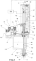
- valve assembly according to the invention has been indicated collectively with the numeral 1 and with 100 a machine for filling containers with liquids that is equipped with a valve assembly 1 according to the invention.
- valve assembly 1 that will be described and subsequently the filling machine 1.
- the valve assembly 1 for a machine for filling containers with liquids is suitable for regulating the filling of a container B with the liquid contained within a tank of said filling machine and to this end it is fluidically connected to such tank.
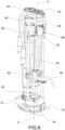
- the valve assembly 1 comprises an adduction conduit 10 that extends along a valve axis X and that is fluidically connectable to the tank 110 of said filling machine 100 in order to enable the inflow of said liquid from the tank 110 to the container B to be filled through a discharge mouth 10a.
- the adduction conduit 10 is defined by a tubular body that is coaxial to valve axis X.
- Such tubular body is intended to be mechanically connected to the bottom 111 of the tank, externally thereto, in such a way as to fluidically connect itself to a discharge opening 112 obtained on the same bottom 111 of the tank at a first end opposite to that wherein said discharge mouth 10a is obtained.
- the valve assembly 1 comprises a shutter 20 that is suitable for regulating the inflow of said liquid into said container B through the adduction conduit 10.
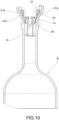
- the shutter 20 is movably arranged inside said adduction conduit 10 in order to be moved along the valve axis X between a closing position, wherein the shutter intercepts the adduction conduit 10 closing the flow section towards the discharge mouth 10a (see Figure 10 ), and one or more opening positions, in which the shutter does not intercept (see Figure 8 ) or only partially intercepts (see Figure 9 ) the adduction conduit 10 leaving a flow section towards the discharge mouth 10a open.
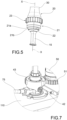
- the shutter 20 preferably carries an associated deflector 15 that extends coaxially from the lower end of the shutter 20 and is suitable for inserting itself in use into the container B in order to guide the liquid out of the discharge mouth 10a towards the walls of the container B.
- the deflector 15 inserts itself into the initial part of the neck of the bottle.
- the shutter 20 comprises an annular gasket 21 (coaxial to the shutter) that sealingly engages an abutment seat 11 with the shutter in the closed position.
- abutment seat 11 is abutment seat 11
- the shutter 20 may be provided with a centering guide 23 consisting of an annular strip that is coaxial to the valve axis X and wherefrom a plurality of radial fins extend wherebetween there remain delimited conduits for the free passage of liquid.
- the radial fins are intended to slide along a cylindrical portion of the adduction conduit, acting as centering elements for the shutter inside the adduction conduit.
- the valve assembly 1 furthermore comprises a tubular control stem 30 for driving the shutter 20.
- tubular control stem 30 In more detail as shown in Figure 2 , the tubular control stem 30:
- the shutter 20 is coaxially associated with the lower end of said stem 30.
- the valve assembly 1 furthermore comprises a probe 40 for detecting the filling level of the container.
- the probe 40 for detecting the filling level of the container is a refractive optic fiber probe.
- a conductive probe exhibits immediate response (depending upon the signal conversion electronics), but has the problem of having difficulty in discriminating against foam which nonetheless acts as a conductor. Also available are wave guide or capacitive type probes but they exhibit very slow response times.
- the probe 40 (preferably optic fiber) has a single measurement point in proximity to the tip.
- the probe 40 is coaxially inserted inside the axial conduit defined by the control stem 30 to be moved between at least one extracted position, wherein it exits from said conduit so as to be inserted inside the container B (see Figures 8 and 9 ), and a retracted position, wherein it does not exit from said conduit so as not to engage the container B (see Figure 10 ).
- the probe 40 is coaxially inserted inside the deflector 15, which consists in a tubular extension to the control stem 30.
- annular gap 41 acts as an air return conduit and is fluidically selectively connectable to the tank or to a plurality of circuits of the filling machine by means of respective valves, preferably installed in a valve block 70.
- the valve assembly 1 comprises:
- said fist 50 and said second electric motor 60 are controllable independently from each other to respectively regulate:
- valve assembly 1 makes it possible to implement the regulation of the bottle level using flow partialization adapting itself in a flexible manner to variations in the bottle format.
- the liquid level rate of ascent must be as high as possible during the filling of the bottle, whilst it must be as low as possible (also at a value of 5%) when the neck of the bottle is filling in order to obtain a rate of ascent that is sufficiently slow to allow the probe to detect the level and to allow the shutter to close itself without, in the meantime, compromisingly changing the level.
- valve assembly 1 may be managed in the following preferred manner.
- the first probe position may be controlled in a very precise manner. It is therefore possible to choose such first position as a function of the bottle format based upon preset data.
- each bottle format has, in particular, a different neck conformation. It follows that as the shape of the neck varies, so does the height position relative to the bottom of the bottle of the transition zone from the full section of the bottle to the restricted section of the neck. Such transition zone is important since thereabove it is opportune to proceed with filling the bottle using a partialized flow rate so as to have the possibility of precisely controlling the filling, thereby avoiding sudden and difficult-to-control rises in the fluid level at the neck of the bottle.
- the first position of the probe 40 is chosen as a function of the aforementioned transition zone.
- the use of an electric motor for the positioning of the probe makes it possible to perform such positioning in an extremely precise manner, so as to adapt itself smoothly to various bottle formats.
- the filling may not only be managed using partialization of the flow rate but also using multiple partializations using multiple level detection points.
- a first partialization of the flow rate may be performed (40% for example) at a first filling level having, for example, the objective of absorbing the foam.
- a second filling level greater than the first by some centimeters
- those points wherein the liquid is detected using the probe may also be more than two.
- the containers B to be filled are abutted against a water tight bottle seal 14 associated with the discharge mouth 10a in a position that is coaxial to the flow deflector 15, to the probe 40 (preferably a optic fiber probe) and to the adduction conduit 10 together with the shutter 20.
- the tank 110 contains the liquid to be filled L to a controlled level. Such liquid fills, by gravity, the entire adduction conduit 10 up to the annular gasket 21 housed within the shutter 20. Above the liquid there is gas that may be contained under pressure; the tank is closed above using a membrane 16 that separates the food area from the unsanitized control area. At the upper part thereof the tank 110 supports the valve block 70 with housed valves V which functionally manage the filling process.
- the shutter 20 is guided by the centering guide 23 and by a piston 24 and supports the deflector 15 at the lower end thereof. When the shutter is raised, a free conduit is formed for the liquid which descends through the adduction conduit 10, crosses the discharge mouth 10a, lapping the deflector 15 up to the container arranged below.
- the annular gasket 21 has a special shape that enables a more controlled outflow than normal gaskets in the case of small shutter openings.
- the shutter 20 has a tubular shape and houses the probe 40 thereinside.
- the probe slides vertically, guided by the deflector 15 and by a guide element 27 (arranged above the tank) and forms, together with the shutter 20, the aforementioned annular gap 41 which acts as an air return conduit and as a channel of communication with the valves V.
- the conduit defined by the gap 41 is diverted through a gasket 26, a block 25 and a flexible tube 75 up to the valve block 70 where it may be placed in communication with:
- the shutter 20 is integral to the block 25 due to the blocking between a striker 24 and a manifold 28.
- the block 25 is laterally mounted on two bearings 42 which roll on a cam 43.
- the shutter is thus pressed against the cam 43 by the spring 44 (which acts upon the piston 24 that is integral to the shutter 20) and regulated in height during filling by the cam 43 itself which is positioned by controlling the angular position thereof.
- the block 25 also performs anti-rotation in dragging on the walls of a base plate 44 that is integral to the tank 110.
- the base plate 44 is made of a plastic material so as to isolate the tank which is subject to sanitization with respect to the movement control area which is not subject to sanitization.
- the base plate 44 is in turn integral to the support element 45 which is configured to support the first electric motor 50 using the pinion 51 thereof and a support bush 52.
- the latter is integral to the washer 42 which, in turn, makes the gear wheel with the cam 43 to rotate.
- the pinion 51 makes the gear wheel 43 to rotate, which, being conformed with a cam at the bottom, presses down on the bearings 42, which are integral to the shutter 20, and causes the opening or closing of the flow insofar as the spring 44, as mentioned, is always pushing the shutter upwards.
- the bush 52 is screwed onto the support 45 and is blocked by a protection cover 46 in such a way as to regulate the shutter closure force on the basis, also, of the effective dimensions of the tank 110 as regards the distance between the abutment seat 11 of the annular gasket 21 and the fixing plane of the base plate 44.
- probe 40 sanitization means may be included that are suitable for completely sanitizing the entire outer surface of the probe 40.
- a sanitizing/detergent fluid is inserted through a washing conduit 80 in a sleeve 81.
- Such fluid when the probe 40 is arranged at a wash window 82, may exceed the aforementioned gasket 26.
- the aforementioned annular gasket 21 in turn comprises:
- the annular gasket 21 therefore defines two different areas for sealing against the abutment seat.
- a first sealing area is defined by the first annular portion 21a, whilst the second sealing area is defined by the second annular portion 21b.
- the first annular portion 21b is axially arranged in relation to the second annular portion 21b in such a way as to abut against the truncated-conical portion 11a of the abutment seat 11 and to make a seal therewith within said predefined axial excursion of the shutter when the second annular portion 21b has already started to make a seal within the cylindrical portion 11b of the abutment seat 11.
- the portion of the gasket that first makes a seal against the abutment seat is the second annular portion 21b.
- the first annular portion 21a makes a seal when the second annular portion 21b is already under sealed conditions.
- the portion of the gasket that first interrupts the seal against the abutment seat is the first annular portion 21a.
- the second annular portion 21b is still sealed whilst the first annular portion 21a has separated from the abutment seat 11.
- At least one flow window 22 is obtained on the second annular portion 21b, which interrupts the annular continuity of the second annular portion 21b and has a predefined angular amplitude.
- such flow window 22 enables a partialized flow of liquid through the adduction conduit within said predefined axial excursion of the shutter when said first annular portion 21a is still spaced apart from the abutment seat and cannot make a seal.
- the angular amplitude of the flow window 22 may be of between 28° e 32° so as to ensure an ascent rate of around 10 mm/s.
- the angular amplitude of the flow window 22 may be less than 28°.
- the angular amplitude of the flow window 22 may be less than 32°.
- the flow window 22 extends up to said first annular portion 21a.
- a valve assembly 1 provided with an annular gasket as described above and having the aforementioned flow window 22 makes it possible to control the flow of fluid within a wider range of axial shutter displacements compared to a valve assembly equipped with a conventional seal without a flow window.
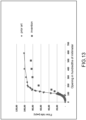
- FIG 13 there are two graphs relating to volumetric flow rate as a function of the opening extent of the shutter, respectively, in a valve assembly with a shutter that is provided with a known water tight gasket and in a valve assembly with a shutter that is provided with the water tight gasket with a flow window.
- the graph with the diamond shaped points relates to the flow rate of the known type of valve assembly; the graph with the square shaped points relates to the flow rate of the valve assembly according to the invention with a gasket provided with a flow window.
- valve assembly according to the invention with a gasket provided with a flow window there is an increase in flow rate that is distributed over a greater, and therefore more manageable, range of shutter heights.
- a machine 100 for filling containers with liquids according to the invention will now be described.
- the machine is intended for the bottling of containers B with gaseous or non-gaseous food liquids.
- the filling machine 100 is inserted, in a completely traditional manner, into a bottling plant or line provided with multiple machines working in succession, and is arranged, in particular, downstream of a rinsing machine and upstream of a capping machine.
- the containers B are transferred from one machine to the other by means of transport lines, such as belt conveyors for example, or by means of conveying equipment such as star wheel conveyors, augers, etc.
- the filling machine 100 is conventionally provided with an input station where it receives the container to be filled from a first transportation line (by means, for example, of a first star wheel conveyor), and an output station, wherein the filled containers are released onto a second transportation line (by means, for example, of a second star wheel conveyor) in order to be conveyed towards a machine arranged downstream, such as for example a capping machine.
- a first transportation line by means, for example, of a first star wheel conveyor
- a second transportation line by means, for example, of a second star wheel conveyor
- the filling machine 100 is provided with a support structure 120, whereupon a rotating turret 130 is revolvingly mounted and carried in rotation around an axis of rotation by means of motor means of a known type (not shown).
- the rotating turret 130 is provided with a tank 110, preferably of an annular shape, wherein the liquid to be bottled is contained.
- the tank 110 is filled with the liquid to be bottled up to a certain height level, whereabove it is filled with an inert gas (for example nitrogen).
- an inert gas for example nitrogen.
- Such inert gas is kept substantially at atmospheric pressure in the case wherein the filling machine 100 is of the gravity type, under slight vacuum in the case wherein the filling machine 1 is of the slight negative pressure type and under pressure in the case wherein the filling machine 100 is of the "isobaric" type for treating gaseous liquids.
- the rotating turret 130 carries a plurality of peripherally mounted valve assemblies 1 uniformly distributed along the circumference thereof, and suitable for transferring the liquid from the tank 110 to the containers B therebelow to be filled, generally consisting of glass or plastic bottles.
- the rotating turret 130 comprises a support base (not shown in the figures) that is rotationally associated with the support structure 120, preferably by means of a thrust bearing (not shown).
- the base supports the tank 110 by means of a plurality of columns that have the function of varying the distance between the base and the tank as a function of the height of the containers B to be filled.
- the support base furthermore peripherally carries means 140 for supporting the containers in relation to those valve assemblies 1 that are associated with the tank.
- Such support means 140 may be actuated so as to move between a first position, wherein they carry the mouth of the container B under sealed conditions with an adduction conduit 10 of the corresponding valve assembly 1, and a second position, wherein they receive the container B when they transit within the input station 3 of the filling machine 1.
- the support means 140 of the containers B comprise a plurality of support structures 141, peripherally mounted on the rotating turret 130 below corresponding valve assemblies 1 and intended to receive in support the containers B during the operational movement thereof upon the rotating turret 130.
- each support structure 141 is driven so as to move itself between the aforementioned first position and the aforementioned second position by means of a fixed cam (not shown), arranged around the rotating turret 130, and acting with a shaped profile on a cam follower (consisting, for example, of an idler wheel) attached to the corresponding support structure 141.
- the support means 140 are of a traditional type and in being well known to a skilled person in the art will not be described in more detail.
- the filling machine 100 object of the present invention, comprises a logic control unit 200 (preferably comprising a PLC) suitable for automatically managing the operation of said filling machine.
- a logic control unit 200 preferably comprising a PLC
- the rotating turret 130 comprises a plurality of manifolds and circuits with process fluids. Such manifolds and circuits are functional for performing the different operational steps involved in the filling cycle of the filling machine 100.
- each valve assembly 1 is fluidically connected to the aforementioned plurality of circuits and manifolds by means of opportune control valves collectively indicated with V in the accompanying Figures.
- control valves V of each valve assembly 1 are preferably of a pneumatic type, and are actuated by means of the introduction of pressurized gas from a pressurized gas source (not shown) driven by the logic control unit 200 of the filling machine 1.
- the operational steps of the filling cycle are the following:
- steps 4) and 6) are not included.
- the rotating turret 130 of the filling machine 100 may therefore comprise all or part of the following circuits or manifolds:
- valve assemblies are valve assemblies 1 according to the invention and in particular as previously described.
- the logic control unit 200 is programmed so as to manage each valve assembly during the filling of the respective container according to predefined operating steps, regulating the axial position of the shutter and the axial position of the probe by means of the first electric motor 50 and the second electric motor 60, respectively.
- the logic control unit 200 is preferably programmed so as to manage each valve assembly during the filling of the respective container according to the following operational steps:
- step b) is carried out with step a) already started.
- the logic control unit 200 may be programmed so as to manage each valve assembly during the filling of the respective container with one or more steps of partializing the flow at different filling levels of the container B. Such steps of partializing the flow may be conducted before and/or after the fast filling step (step a) and before the final slow filling step (step c).
- the logic control unit 200 may be programmed so as to manage each valve assembly during the filling of the respective container with a further operating step f) which is conducted before said step a) and which includes moving the shutter 20 along the valve axis X by driving the first electric motor 50 to move the shutter from the closing position to a partial opening position so as to start a slow filling step of the container.
- the logic control unit 200 may be programmed to regulate the predefined intermediate filling level as a function of the format of the container treated in each valve assembly and/or based on the foaminess of the liquid, based on preset data.
- the logic control unit 200 may be programmed to regulate the axial position taken by the shutter and thus the flow section as a function of the desired liquid flow rate during a specific filling step of the container, based on preset data.
- the filling may not only be managed using partialization of the flow rate but also using multiple partializations using multiple level detection points.
- a first partialization of the flow rate may be performed (40% of the flow rate for example) at a first filling level having, for example, the objective of absorbing the foam.
- a second filling level greater than the first by some centimeters
- those points wherein the liquid is detected using the probe may also be more than two.
- the invention allows numerous advantages to be obtained, which have already been described in part.
- valve assembly for a filling machine with a filling level regulation probe makes it possible to implement the regulation of the bottle level using flow partialization in adapting itself in a flexible manner to variations in the bottle format.
- valve assembly according to the invention makes it possible to regulate the bottle level using very precise flow rate partialization.
- valve assembly according to the invention is simple and economical to manufacture.
Landscapes
- Physics & Mathematics (AREA)
- Fluid Mechanics (AREA)
- Filling Of Jars Or Cans And Processes For Cleaning And Sealing Jars (AREA)
Applications Claiming Priority (1)
| Application Number | Priority Date | Filing Date | Title |
|---|---|---|---|
| IT202300009726 | 2023-05-15 |
Publications (2)
| Publication Number | Publication Date |
|---|---|
| EP4464652A1 true EP4464652A1 (de) | 2024-11-20 |
| EP4464652B1 EP4464652B1 (de) | 2025-12-24 |
Family
ID=87514354
Family Applications (1)
| Application Number | Title | Priority Date | Filing Date |
|---|---|---|---|
| EP24167168.4A Active EP4464652B1 (de) | 2023-05-15 | 2024-03-28 | Ventilanordnung für eine füllmaschine mit füllstandsregelsonde und füllmaschine mit einem solchen ventil |
Country Status (7)
| Country | Link |
|---|---|
| US (1) | US20240383740A1 (de) |
| EP (1) | EP4464652B1 (de) |
| AR (1) | AR132679A1 (de) |
| AU (1) | AU2024203125A1 (de) |
| CL (1) | CL2024001439A1 (de) |
| ES (1) | ES3058066T3 (de) |
| PT (1) | PT4464652T (de) |
Families Citing this family (2)
| Publication number | Priority date | Publication date | Assignee | Title |
|---|---|---|---|---|
| CN120100515B (zh) * | 2025-05-07 | 2025-08-12 | 飞翼股份有限公司 | 一种供液装置 |
| CN121044529B (zh) * | 2025-11-03 | 2026-02-24 | 成都味科自动化设备有限公司 | 一种具有回液结构的阀门 |
Citations (11)
| Publication number | Priority date | Publication date | Assignee | Title |
|---|---|---|---|---|
| US3783912A (en) | 1968-12-30 | 1974-01-08 | Ato Inc | Beverage container filling head |
| US4386635A (en) | 1980-03-12 | 1983-06-07 | Seitz-Werke Gmbh | Method for controlling electrically controlled filling elements and system for carrying out the method |
| DE3218062A1 (de) | 1982-05-13 | 1983-11-17 | Holstein Und Kappert Gmbh, 4600 Dortmund | Verfahren zum abfuellen von fluessigkeiten in behaelter wie flaschen, dosen und dgl. |
| EP0458093A2 (de) * | 1990-05-05 | 1991-11-27 | KHS Maschinen- und Anlagenbau Aktiengesellschaft | Füllelement |
| EP0598892A1 (de) | 1992-06-19 | 1994-06-01 | Krones Ag Hermann Kronseder Maschinenfabrik | Vorrichtung zur einstellung der füllhöhe in füllmaschinen für gefässe |
| EP0601514A1 (de) | 1992-12-10 | 1994-06-15 | KHS Maschinen- und Anlagenbau Aktiengesellschaft | Füllmaschine, insbesondere Gegendruck-Füllmaschine |
| EP0658511A1 (de) | 1993-12-16 | 1995-06-21 | KHS Maschinen- und Anlagenbau Aktiengesellschaft | System zum Abfüllen eines flüssigen Füllgutes in Flaschen, Dosen oder dergl. Behälter |
| EP2192076A1 (de) | 2008-12-01 | 2010-06-02 | Newtec Filling Systems | Vorrichtung zum Füllen einer Flasche und entsprechendes automatisches System zum Füllen von Flaschen |
| EP2343518A1 (de) | 2009-12-23 | 2011-07-13 | Krones AG | Messsonde zum Bestimmen eines Füllstandes einer Flüssigkeit |
| EP2604572A1 (de) | 2011-12-13 | 2013-06-19 | Krones AG | Füllorgan zum Befüllen von Behältern |
| EP3919431A1 (de) * | 2020-06-05 | 2021-12-08 | Kosme S.r.l. Unipersonale | Fülleinheit zum befüllen von behältern zweier verschiedener typen mit einer flüssigen substanz, insbesondere mit einem getränk |
Family Cites Families (6)
| Publication number | Priority date | Publication date | Assignee | Title |
|---|---|---|---|---|
| DE29513031U1 (de) * | 1995-08-17 | 1996-09-12 | Krones Ag Hermann Kronseder Maschinenfabrik, 93073 Neutraubling | Gefäßfüllmaschine |
| US6226081B1 (en) * | 1997-03-24 | 2001-05-01 | Optikos Corporation | Optical height of fill detection system and associated methods |
| DE102004011101B4 (de) * | 2004-03-06 | 2011-04-07 | Khs Gmbh | Füllelemente sowie Füllmaschine mit derartigen Füllelementen |
| DE102016118474A1 (de) * | 2016-09-29 | 2018-03-29 | Krones Ag | Vorrichtung zum Beeinflussen des Volumenstroms eines Füllprodukts in einer Abfüllanlage |
| US9915389B1 (en) * | 2017-02-06 | 2018-03-13 | Emerson Process Management Regulator Technologies, Inc. | Mechanically-retained sealing disks for use with fluid regulators |
| IT202000013450A1 (it) * | 2020-06-05 | 2021-12-05 | Kosme Srl Unipersonale | Unità di riempimento per riempire contenitori di due tipologie differenti con una sostanza liquida, in particolare con una bevanda |
-
2024
- 2024-03-28 ES ES24167168T patent/ES3058066T3/es active Active
- 2024-03-28 EP EP24167168.4A patent/EP4464652B1/de active Active
- 2024-03-28 PT PT241671684T patent/PT4464652T/pt unknown
- 2024-05-10 US US18/660,701 patent/US20240383740A1/en active Pending
- 2024-05-10 AU AU2024203125A patent/AU2024203125A1/en active Pending
- 2024-05-14 CL CL2024001439A patent/CL2024001439A1/es unknown
- 2024-05-14 AR ARP240101216A patent/AR132679A1/es unknown
Patent Citations (11)
| Publication number | Priority date | Publication date | Assignee | Title |
|---|---|---|---|---|
| US3783912A (en) | 1968-12-30 | 1974-01-08 | Ato Inc | Beverage container filling head |
| US4386635A (en) | 1980-03-12 | 1983-06-07 | Seitz-Werke Gmbh | Method for controlling electrically controlled filling elements and system for carrying out the method |
| DE3218062A1 (de) | 1982-05-13 | 1983-11-17 | Holstein Und Kappert Gmbh, 4600 Dortmund | Verfahren zum abfuellen von fluessigkeiten in behaelter wie flaschen, dosen und dgl. |
| EP0458093A2 (de) * | 1990-05-05 | 1991-11-27 | KHS Maschinen- und Anlagenbau Aktiengesellschaft | Füllelement |
| EP0598892A1 (de) | 1992-06-19 | 1994-06-01 | Krones Ag Hermann Kronseder Maschinenfabrik | Vorrichtung zur einstellung der füllhöhe in füllmaschinen für gefässe |
| EP0601514A1 (de) | 1992-12-10 | 1994-06-15 | KHS Maschinen- und Anlagenbau Aktiengesellschaft | Füllmaschine, insbesondere Gegendruck-Füllmaschine |
| EP0658511A1 (de) | 1993-12-16 | 1995-06-21 | KHS Maschinen- und Anlagenbau Aktiengesellschaft | System zum Abfüllen eines flüssigen Füllgutes in Flaschen, Dosen oder dergl. Behälter |
| EP2192076A1 (de) | 2008-12-01 | 2010-06-02 | Newtec Filling Systems | Vorrichtung zum Füllen einer Flasche und entsprechendes automatisches System zum Füllen von Flaschen |
| EP2343518A1 (de) | 2009-12-23 | 2011-07-13 | Krones AG | Messsonde zum Bestimmen eines Füllstandes einer Flüssigkeit |
| EP2604572A1 (de) | 2011-12-13 | 2013-06-19 | Krones AG | Füllorgan zum Befüllen von Behältern |
| EP3919431A1 (de) * | 2020-06-05 | 2021-12-08 | Kosme S.r.l. Unipersonale | Fülleinheit zum befüllen von behältern zweier verschiedener typen mit einer flüssigen substanz, insbesondere mit einem getränk |
Also Published As
| Publication number | Publication date |
|---|---|
| EP4464652B1 (de) | 2025-12-24 |
| US20240383740A1 (en) | 2024-11-21 |
| AU2024203125A1 (en) | 2024-12-05 |
| ES3058066T3 (en) | 2026-03-06 |
| CL2024001439A1 (es) | 2024-08-09 |
| PT4464652T (pt) | 2026-01-07 |
| AR132679A1 (es) | 2025-07-23 |
Similar Documents
| Publication | Publication Date | Title |
|---|---|---|
| EP4464652B1 (de) | Ventilanordnung für eine füllmaschine mit füllstandsregelsonde und füllmaschine mit einem solchen ventil | |
| EP1995208B1 (de) | Rotationsfüllmaschine zur Füllung von Behältern mit Flüssigkeiten | |
| CN101437747B (zh) | 灌装单元及具有灌装单元的灌装机 | |
| EP3453673B1 (de) | Maschine mit einem füllstandskorrektursystem zum befüllen von behältern mit flüssigkeiten | |
| US7647950B2 (en) | Beverage bottling plant with a beverage bottle filling machine for filling beverage bottles, and filling elements for the beverage bottle filling machine | |
| US10040582B2 (en) | Filling devices for isobaric filling machines for filling bottles with alimentary liquids | |
| EP1908726B1 (de) | Isobare Rotationsfüllmaschine zur Füllung von Containern mit Flüssigkeiten | |
| US9604834B2 (en) | Filler element comprising a Trinox tube | |
| EP2958851B1 (de) | Füllvorrichtung für füllmaschinen zum füllhöfen-befüllen von flaschen mit flüssignahrungsmitteln | |
| US12195317B2 (en) | Device and method for filling a container with a filling product | |
| CA1172216A (en) | Automatic bottle filling device, and facility using same | |
| US4317475A (en) | Liquid filling and level sensing apparatus | |
| US12421101B2 (en) | Valve assembly for a filling machine and a filling machine provided with such valve | |
| WO2010131271A1 (en) | Filling method and valve | |
| JP2017206299A (ja) | 充填機、充填方法、および充填システム | |
| US8863789B2 (en) | Method and filling system for filling containers in a pressurized manner | |
| WO2019043585A1 (en) | FILLER | |
| EP3473588A1 (de) | Vorrichtung und verfahren zum füllen von behältern mit einem fliessfähigen produkt unter druck | |
| US4174005A (en) | Fluid pressure measuring device | |
| EP3473589A1 (de) | Füllmaschine und verfahren zum füllen von behältern mit einem rieselfähigen produkt unter druck | |
| GB1580939A (en) | Valve for isobarometric racking machines | |
| UA20744U (en) | Machine for automatic distribution of liquid products into containers |
Legal Events
| Date | Code | Title | Description |
|---|---|---|---|
| PUAI | Public reference made under article 153(3) epc to a published international application that has entered the european phase |
Free format text: ORIGINAL CODE: 0009012 |
|
| STAA | Information on the status of an ep patent application or granted ep patent |
Free format text: STATUS: THE APPLICATION HAS BEEN PUBLISHED |
|
| AK | Designated contracting states |
Kind code of ref document: A1 Designated state(s): AL AT BE BG CH CY CZ DE DK EE ES FI FR GB GR HR HU IE IS IT LI LT LU LV MC ME MK MT NL NO PL PT RO RS SE SI SK SM TR |
|
| STAA | Information on the status of an ep patent application or granted ep patent |
Free format text: STATUS: REQUEST FOR EXAMINATION WAS MADE |
|
| 17P | Request for examination filed |
Effective date: 20250226 |
|
| GRAP | Despatch of communication of intention to grant a patent |
Free format text: ORIGINAL CODE: EPIDOSNIGR1 |
|
| STAA | Information on the status of an ep patent application or granted ep patent |
Free format text: STATUS: GRANT OF PATENT IS INTENDED |
|
| INTG | Intention to grant announced |
Effective date: 20250805 |
|
| GRAS | Grant fee paid |
Free format text: ORIGINAL CODE: EPIDOSNIGR3 |
|
| GRAA | (expected) grant |
Free format text: ORIGINAL CODE: 0009210 |
|
| STAA | Information on the status of an ep patent application or granted ep patent |
Free format text: STATUS: THE PATENT HAS BEEN GRANTED |
|
| P01 | Opt-out of the competence of the unified patent court (upc) registered |
Free format text: CASE NUMBER: UPC_APP_0010039_4464652/2025 Effective date: 20251016 |
|
| AK | Designated contracting states |
Kind code of ref document: B1 Designated state(s): AL AT BE BG CH CY CZ DE DK EE ES FI FR GB GR HR HU IE IS IT LI LT LU LV MC ME MK MT NL NO PL PT RO RS SE SI SK SM TR |
|
| REG | Reference to a national code |
Ref country code: CH Ref legal event code: F10 Free format text: ST27 STATUS EVENT CODE: U-0-0-F10-F00 (AS PROVIDED BY THE NATIONAL OFFICE) Effective date: 20251224 Ref country code: GB Ref legal event code: FG4D |
|
| REG | Reference to a national code |
Ref country code: DE Ref legal event code: R096 Ref document number: 602024001780 Country of ref document: DE |
|
| REG | Reference to a national code |
Ref country code: PT Ref legal event code: SC4A Ref document number: 4464652 Country of ref document: PT Date of ref document: 20260107 Kind code of ref document: T Free format text: AVAILABILITY OF NATIONAL TRANSLATION Effective date: 20251229 |
|
| REG | Reference to a national code |
Ref country code: ES Ref legal event code: FG2A Ref document number: 3058066 Country of ref document: ES Kind code of ref document: T3 Effective date: 20260306 |
|
| REG | Reference to a national code |
Ref country code: LT Ref legal event code: MG9D |
|
| PG25 | Lapsed in a contracting state [announced via postgrant information from national office to epo] |
Ref country code: NO Free format text: LAPSE BECAUSE OF FAILURE TO SUBMIT A TRANSLATION OF THE DESCRIPTION OR TO PAY THE FEE WITHIN THE PRESCRIBED TIME-LIMIT Effective date: 20260324 |
|
| PGFP | Annual fee paid to national office [announced via postgrant information from national office to epo] |
Ref country code: DE Payment date: 20260325 Year of fee payment: 3 |
|
| PG25 | Lapsed in a contracting state [announced via postgrant information from national office to epo] |
Ref country code: FI Free format text: LAPSE BECAUSE OF FAILURE TO SUBMIT A TRANSLATION OF THE DESCRIPTION OR TO PAY THE FEE WITHIN THE PRESCRIBED TIME-LIMIT Effective date: 20251224 Ref country code: HR Free format text: LAPSE BECAUSE OF FAILURE TO SUBMIT A TRANSLATION OF THE DESCRIPTION OR TO PAY THE FEE WITHIN THE PRESCRIBED TIME-LIMIT Effective date: 20251224 |
|
| PGFP | Annual fee paid to national office [announced via postgrant information from national office to epo] |
Ref country code: AT Payment date: 20260301 Year of fee payment: 3 |
|
| PG25 | Lapsed in a contracting state [announced via postgrant information from national office to epo] |
Ref country code: RS Free format text: LAPSE BECAUSE OF FAILURE TO SUBMIT A TRANSLATION OF THE DESCRIPTION OR TO PAY THE FEE WITHIN THE PRESCRIBED TIME-LIMIT Effective date: 20260324 |
|
| PGFP | Annual fee paid to national office [announced via postgrant information from national office to epo] |
Ref country code: FR Payment date: 20260227 Year of fee payment: 3 |