EP1908680B1 - Système de toit ouvrant - Google Patents
Système de toit ouvrant Download PDFInfo
- Publication number
- EP1908680B1 EP1908680B1 EP20070253783 EP07253783A EP1908680B1 EP 1908680 B1 EP1908680 B1 EP 1908680B1 EP 20070253783 EP20070253783 EP 20070253783 EP 07253783 A EP07253783 A EP 07253783A EP 1908680 B1 EP1908680 B1 EP 1908680B1
- Authority
- EP
- European Patent Office
- Prior art keywords
- chain
- block
- flange
- panel
- carriage
- Prior art date
- Legal status (The legal status is an assumption and is not a legal conclusion. Google has not performed a legal analysis and makes no representation as to the accuracy of the status listed.)
- Active
Links
Images


Classifications
-
- B—PERFORMING OPERATIONS; TRANSPORTING
- B63—SHIPS OR OTHER WATERBORNE VESSELS; RELATED EQUIPMENT
- B63B—SHIPS OR OTHER WATERBORNE VESSELS; EQUIPMENT FOR SHIPPING
- B63B17/00—Vessels parts, details, or accessories, not otherwise provided for
- B63B17/02—Awnings, including rigid weather protection structures, e.g. sunroofs; Tarpaulins; Accessories for awnings or tarpaulins
Definitions
- the present invention relates to a sliding sunroof system.
- the system is particularly suitable for use on a boat, especially a luxury pleasure boat.
- roof panels similar in concept to a car sunroof.
- Such roofs provide the user with a degree of flexibility when steering a boat in respect of their being open to the weather conditions.
- roof panels are constructed from lightweight materials they are nevertheless still heavy and means are normally included to facilitate movement between the closed position and a partially or fully open position.
- Features which provide smooth or low friction movement are known, but increasingly motors are included to drive the panel.
- EP 1 524 183 A1 discloses a movement system for an operable roof of a vehicle, in particular a boat, for mounting at the site of an opening formed in the roof of the vehicle for movably supporting at least one closure element for selectively covering the opening.
- the system includes a pair of elongate support modules configured as rectilinear bars, for mounting on the roof of the vehicle on opposite sides of the opening.
- Each support element has a track element extending substantially parallel to the support element with one or more carriage elements, connectable to the closure element, mounted thereon for longitudinal sliding.
- the system also includes transmission means for imparting movement controlled by a motor to at least one of the carriage elements.
- the transmission means include a belt member connected to at least one of the carriage elements and closed in a loop about two end pulleys so as to form two belt branches extending longitudinally along the support members, which are spaced by a distance substantially the same as a transverse dimension of the carriage elements.
- a final consideration for a sunroof system is its ease of installation and, where necessary, repair. It would be advantageous therefore if a system were to be easy to incorporate into a boat design.
- the system can be easily installed and allows the panels to move freely between an open and closed position whilst allowing the panel to safely flex.
- the system includes a chain guide located within the channel, the chain guide separating portions of the chain moving in opposite directions.
- the guide reduces wear and tear on the chain and prevents undesired motion and harmonics building up.
- the chain guide is particularly preferably in two sections to facilitate assembly. Especially preferably the two sections are so profiled to provide one or more gaps between the sections along contacting surfaces. The provision of the gaps minimises the chance of the sections not sitting well against each other.
- connection means preferably engages the flange elements by means of rollers.
- the rollers run on the flange elements to provide a smooth operation.
- the or each roller includes one or more flanges, engaging the edge of the flange elements. The flanges on the roller prevent lateral movement of the panel with respect to the guide rails.
- connection means optionally includes a block engaging the underside of a flange element and gripping the flange element between the block and a roller.
- the block is formed of resilient material to dampen down vibrations.
- the block includes resilient means. Such vibrations, arising for example from the motion of the boat or from the engine can cause noise and also wear on the system elements.
- the block is yet further optionally urged against the flange element by a pin or similar fixing means to ensure good contact.
- connection means is operably connected to the chain by a toothed pick up, the teeth of the pick up sitting into the gaps between the links in the chain.
- a brush pile is advantageously located in the guide rail to reduce noise and to hinder ingress of dirt into the rail which might cause damage.
- the system preferably includes tensioning means adjustable to remove slack from the chain.
- the attached drawings show a system to enable a sunroof panel to be moved between an open and closed position.
- the system moreover provided is designed to be robust towards flexing of the panel and to minimise the noise produced during panel movement.
- the system is designed primarily for use within luxury boats. Typically such boats are of length 15 to 30 metres and the panels under consideration approximately rectangular in shape and of dimension 2-4 metres.
- Such panels are designed to be relatively strong but lightweight and can be formed of plastics materials, glass fibre or carbon composites.
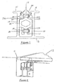
- a prime component is an elongate guide rail 10, formed from aluminium or steel, which is set into a gutter or channel 11 beneath a roof panel 12.
- the guide rail 10 has a base plate 13.
- Two side walls 14 depend perpendicularly upwardly, from the base plate 13 to define a U-shaped channel.
- Flanges 15, 16 are located perpendicularly across the free edge of each side wall 14, and provide support for movement of the panel 12.
- an endless chain 17 of typically 3 ⁇ 8" (0.95cm) pitch is provided, the chain being operably connected to a motor and to the panel 12.
- the chain 17 is located wholly within the U-shaped channel of the guide rail 10, and describes an upper path 18 and a lower path 19 as part of a loop.
- the lower path 19 of the chain 17 is supported by a ridge 21 on a lower chain guide 20.
- Resting on the lower chain guide 20 is an upper chain guide 22.
- the upper chain guide 22 has a first ridge 23 which depends downwardly from the upper chain guide 22, co-operating with the ridge 21 to constrain lateral and vertical motion of the chain 17.
- This feature reduces wear on the chain 17, and also noise due to rattling of the chain 17. Moreover, impact of the boat's motion on the chain's motion is minimised.
- a second ridge 24 is also provided on the upper chain guide 22 to support the chain 17 as it moves along the upper path 18.
- ridges 25a, 25b are provided on the guide rail 10.
- FIGS 3a and 3b illustrate the tensioning block and the drive means.
- tensioning means are provided. Two options for tensioning means are illustrated, which act in similar fashion.
- the tensioning means comprise an idle sprocket 30 around which the chain (not shown in Figures 3a, 3b ) passes.
- the sprocket 30 is connected to the tensioning block 31 whose operation enables the position of the sprocket 30 to be moved within the guide rail 10. By suitable adjustment of this position the effective path length of the chain 17 is altered. This feature facilitates installation of the system and also provides rapid correction if the chain 17 becomes slack after having been in use.
- the location of the sprocket 30 and the tensioning block 31 is at the discretion of the operator and depends upon compatibility with the particular boat in which the system is being used.
- Motion of the chain 17 is provided by a motor which connects through, via a drive shaft 32, to a drive sprocket 33 located within the guide rail 10.
- Figure 3a provides two options for the location of the tensioning block 31.
- Figure 3b shows two options for the location of the drive sprocket 33, the choice of location depending upon the installation position of the motor.
- the drive sprocket 33 is supported by a block which supports the drive shaft 32 and also provides clearance for a carriage (see below) to run over the elements of the tensioning means.
- the drive shaft 32 can be connected to the drive motor via universal joints and coupled shafts, although alternative connections such as flexible drive shafts can be used where suitable.
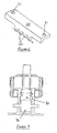
- Motion of the chain 17 is coupled to the roof panel 12 through a carriage 40 illustrated in Figures 4a, 4b and 5 .
- the carriage 40 is connected to and supports the panel 12 and the chain 17, and is itself supported on the guide rail 10.
- the motor drives the chain 17 therefore, the carriage 40 and the panel 12 are moved along in the same direction.
- the carriage 40 has two carriage brackets 41 to provide a support framework for the other carriage elements.
- two rollers 42a, 42b are mounted on axles 43a, 43b.
- the axles 43a, 43b pass through holes defined in the brackets 41. Where suitable, the axles can be incorporated as an integral part of the rollers 42a, 42b.
- Each roller 42a, 42b is profiled by incorporation of roller flanges 44.
- the rollers surfaces 45 rest on the upper surface of the guide rail flanges 15, 16 whilst the roller flanges 44 are contiguous with the inwardly facing edges of the flanges 15,16.
- the roller flanges 44 and the roller surfaces 45 co-operate therefore with the flanges 15,16 to keep the carriage 40 correctly aligned.
- Each bracket 41 also supports a generally elongated block 46 held in position on the bracket 41 by means of fixing means 47 passing through holes in the bracket 41 and into the block 46.
- the block 46 is resilient in nature, resilience being provided firstly by the shape of the block 46 having a cut away portion 48 allowing the remaining portions 49 to flex.
- the block 46 is formed of a resilient material. In use the block 46 engages and is urged against the underside of the lower surface of the flange 15, 16. To further urge the block 46 against the flange 15,16 a pin 50 passes through the block 46.
- roller surfaces 45 therefore co-operate with the block 46 to restrict vertical movement of the carriage 40. Such vertical movement may be occasioned by motion of the boat or engine vibrations.
- connection column 51 The carriage 40 is coupled to the panel 12 by a connection system, simply illustrated as the connection column 51.
- the connection column 51 is typically formed of a material such as to provide a strong member able to withstand the forces generated by the boat and the panel's movement.
- a connection bracket 52 supports and connects the column 51 to the carriage 40.
- a pick-up 60 (shown in Figure 6 ) is fixed to the lower portion of the carriage 40 by fixing means which pass through the apertures 61.
- the pick-up 60 is provided with teeth 62 which sit between the links of the chain 17 and thereby couple the chain 17 to the carriage 40.
- a brush pile 26 is located within the upper portion guide rail 10. The angle of the pile 26 is such that damaging engagement with the flanges 44 is avoided.
- the carriage 40 so described firmly connects the panel 12 to the guide rail 10. Due to the elements of the carriage 40, the panel 12 is free to move in the direction of the guide rail 10 to open and cover an aperture. However, flexing of the panel 12 is restricted so minimising the risk of the panel 12 or the drive means detaching.
- FIG 7 a second embodiment of a system is shown.
- the carriage in Figure 7 is similar to that described above.
- the prime difference between the first and second embodiment is that the chain is replaced by a rack 70 and pinion 71.
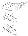
- Figures 8a-8d illustrate alternative means of tensioning the chain 17 in addition to or in conjunction with the means disclosed above.
- the tensioner 80 acts to ensure that the effective length of the chain 17 remains constant irrespective of the motion of the boat or the panel 12 or of thermal expansion between the rail 13 and the chain 17.
- a floating housing 81 houses a series of springs 82-84, connected together in series.
- Further housing pins 83a, 83b connect the central spring 83 to the housing 81, butting up against the downwardly depending wall of the floating housing 81.
- the incorporation of the tensioner 80 within the loop of the chain 17 itself ensures that the tension within the chain 17 remains relatively constant. Moreover, by suitable adjustment of the housings, the tension can be set to a desired value.
- the motor to drive motion of the panel can be incorporated in a number of positions depending upon the particular boat in which the system is installed.
- the motor 90 is mounted at the rear of the boat 91.
- the panel 12 is supported on two guide rails 10 and drive shafts 92 link the motor 90 to the chain 17 within the guide rails 10.
- Figure 9b illustrates a centre-drive option. Again the motor 90 is mounted at the rear of the boat 91. The drive for the panel 12 is however mounted solely in the central guide rail 93. The panel 12 is additionally supported by the side guide rail 94, but no drive mechanism is located within the side guide rail 94.
- Figure 9c illustrates a mid-drive option.
- the motor 90 is mounted centrally with respect to the aperture.
- the panel 12 is supported by and the drive means located in each side guide rail 94, with drive shaft 92 linking the motor to the chain 17 with each guide rail 94.
Landscapes
- Chemical & Material Sciences (AREA)
- Engineering & Computer Science (AREA)
- Combustion & Propulsion (AREA)
- Mechanical Engineering (AREA)
- Ocean & Marine Engineering (AREA)
- Power-Operated Mechanisms For Wings (AREA)
- Seal Device For Vehicle (AREA)
Claims (13)
- Système de toit ouvrant pour un bateau de plaisance, comportant un panneau de toit coulissant (12) capable d'être déplacé entre une position ouverte et une position fermée, le système comprenant une chaîne sans fin (17) raccordée à un panneau (12) par un moyen chariot ; et un moteur pour entraîner la chaîne sans fin (17) ; caractérisé en ce que la chaîne (17) est contrainte à se déplacer à l'intérieur d'un rail de guidage (10) comportant une section de base, avec des parois latérales (14) dépendantes de celle-ci formant un canal en forme de U, le bord libre de chaque paroi latérale (14) se terminant par un élément à bride (15, 16) orienté perpendiculairement à celui-ci et les éléments à brides (15, 16) délimitant un espace entre lesdits bords libres, en laissant le canal ouvert le long d'une surface, le moyen chariot s'engageant dans et étant supporté par les surfaces des éléments à brides (15, 16).
- Système de toit ouvrant selon la revendication 1, caractérisé en ce que le système comprend un guide de chaîne situé à l'intérieur du canal, le guide de chaîne séparant des parties de la chaîne (17) qui se déplacent dans des sens opposés.
- Système selon la revendication 2, caractérisé en ce que le guide de chaîne est en deux sections pour faciliter l'assemblage.
- Système selon la revendication 3, caractérisé en ce que les deux sections sont profilées de façon à former un ou plusieurs espaces entre les sections le long des surfaces en contact.
- Système selon l'une quelconque des revendications précédentes, caractérisé en ce que le moyen chariot s'engage dans les éléments à brides (15, 16) au moyen de galets (42a, 42b).
- Système selon la revendication 5, caractérisé en ce que le ou chaque galet comprend une ou plusieurs brides (44), qui s'engagent dans le bord des éléments à brides (15, 16).
- Système selon l'une quelconque des revendications précédentes, caractérisé en ce que le moyen chariot comprend un bloc (46) qui s'engage dans le dessous d'un élément à bride (15, 16) et bloque l'élément à bride entre le bloc et un galet.
- Système selon la revendication 7, caractérisé en ce que le bloc est formé d'un matériau élastique pour amortir les vibrations.
- Système selon la revendication 7, caractérisé en ce que le bloc comprend un moyen élastique.
- Système selon l'une quelconque des revendications 7 à 9, caractérisé en ce que le bloc est pressé contre l'élément à bride (15, 16) par une broche (50) ou un moyen de fixation similaire pour garantir un bon contact.
- Système selon l'une quelconque des revendications précédentes, caractérisé en ce que le moyen chariot est fonctionnellement raccordé à la chaîne par un élément de reprise denté (60), les dents (62) de l'élément de reprise étant disposées dans les espaces entre les maillons de la chaîne (17).
- Système selon l'une quelconque des revendications précédentes, caractérisé en ce que des poils de brosse (26) sont disposés dans le rail de guidage (10) pour atténuer le bruit et pour empêcher la saleté de pénétrer dans le rail en risquant ainsi de causer des dommages.
- Système selon l'une quelconque des revendications précédentes, comprenant un moyen de tension réglable pour tendre la chaîne.
Applications Claiming Priority (1)
| Application Number | Priority Date | Filing Date | Title |
|---|---|---|---|
| GB0618937A GB0618937D0 (en) | 2006-09-26 | 2006-09-26 | A sunroof system |
Publications (3)
| Publication Number | Publication Date |
|---|---|
| EP1908680A2 EP1908680A2 (fr) | 2008-04-09 |
| EP1908680A3 EP1908680A3 (fr) | 2011-08-03 |
| EP1908680B1 true EP1908680B1 (fr) | 2012-11-21 |
Family
ID=37434683
Family Applications (1)
| Application Number | Title | Priority Date | Filing Date |
|---|---|---|---|
| EP20070253783 Active EP1908680B1 (fr) | 2006-09-26 | 2007-09-25 | Système de toit ouvrant |
Country Status (2)
| Country | Link |
|---|---|
| EP (1) | EP1908680B1 (fr) |
| GB (1) | GB0618937D0 (fr) |
Families Citing this family (4)
| Publication number | Priority date | Publication date | Assignee | Title |
|---|---|---|---|---|
| EP2161192A1 (fr) * | 2008-09-08 | 2010-03-10 | Nautica Tender A/S | Bateau avec toit amovible |
| ITTO20090332A1 (it) * | 2009-04-28 | 2010-10-29 | Franco Tonini | Meccanismo di sollevamento e scorrimento coperture nautiche |
| GB2624396A (en) * | 2022-11-15 | 2024-05-22 | Trend Marine Products Ltd | Carriage and rail mounting assembly, e.g. for a sunroof on a boat |
| CN118419200B (zh) * | 2024-07-05 | 2024-09-10 | 山东博新新材料有限公司 | 一种船用自动篷布 |
Family Cites Families (7)
| Publication number | Priority date | Publication date | Assignee | Title |
|---|---|---|---|---|
| FR1417270A (fr) * | 1964-09-29 | 1965-11-12 | Capot de pont pour bateaux | |
| EP0500850A1 (fr) * | 1990-09-10 | 1992-09-02 | VAN RIE, Freddy | Systeme pour fenetres coulissantes et toits ouvrants |
| US6533349B2 (en) * | 1998-07-27 | 2003-03-18 | Inalfa Industries B.V. | Open roof construction for a vehicle |
| DE19951619A1 (de) * | 1999-10-21 | 2001-04-26 | Michael Koch | Motorboot |
| DE602004000750T2 (de) * | 2004-01-23 | 2007-01-11 | Opac S.R.L. | Modularer Bewegungsunterstützungsystem für ein Fahrzeugdach, insbesondere für ein Boot |
| ITTO20050563A1 (it) * | 2005-08-08 | 2007-02-09 | Azimut Benetti S P A | Gruppo parasole-parabrezza per imbarcazioni |
| FR2892377B1 (fr) * | 2005-10-24 | 2009-07-10 | Thibaut Jean Edouard Tincelin | Protection escamotable d'un pont exterieur de navire |
-
2006
- 2006-09-26 GB GB0618937A patent/GB0618937D0/en not_active Ceased
-
2007
- 2007-09-25 EP EP20070253783 patent/EP1908680B1/fr active Active
Also Published As
| Publication number | Publication date |
|---|---|
| EP1908680A3 (fr) | 2011-08-03 |
| GB0618937D0 (en) | 2006-11-08 |
| EP1908680A2 (fr) | 2008-04-09 |
Similar Documents
| Publication | Publication Date | Title |
|---|---|---|
| US8069610B2 (en) | Adjustable window lifter guide rail | |
| EP1908680B1 (fr) | Système de toit ouvrant | |
| CN102431425B (zh) | 天窗装置 | |
| US9038699B2 (en) | Blind assembly for a vehicle | |
| EP2338716B1 (fr) | Ensemble de pare-soleil et construction de toit ouvert fourni avec celui-ci | |
| EP1524183B1 (fr) | Système modulaire de support de mouvement pour un toit de vehicle ouvrant, en particulier pour un bateau | |
| CN101017969A (zh) | 连接式可运动体的线束安装结构 | |
| KR900007524B1 (ko) | 차량용 썬 루우프(Sun roof)장치 | |
| US7424788B2 (en) | Universal cable window regulator assembly for vehicles | |
| WO2010063312A1 (fr) | Ensemble pare-soleil et construction de toit ouvrant équipée de celui-ci | |
| US20130219794A1 (en) | Window regulator | |
| US8240752B2 (en) | Holding structure of guide pipe of sunroof apparatus | |
| US7337581B2 (en) | Guide assembly for sliding doors or pivotable sliding doors of vehicles and sliding door or pivotable sliding door | |
| JP4848913B2 (ja) | ドア構造 | |
| EP1232888B1 (fr) | Elément de protection pour rail de guidage de toit ouvrant de véhicule | |
| CN1818311A (zh) | 用于车辆的侧面滑门系统 | |
| JP4465000B2 (ja) | サンルーフ装置 | |
| CN1762731A (zh) | 用于滑顶系统的盖 | |
| JP4564542B2 (ja) | クルーザーのオーニングにおけるウィンドーレギュレーター | |
| CN1743196A (zh) | 滑顶系统 | |
| JP2006168439A (ja) | サンルーフ装置のディフレクタ | |
| JP4495569B2 (ja) | サンルーフ装置 | |
| CN101117091A (zh) | 天窗装置中的导架的安装结构 | |
| US20030233791A1 (en) | Window lifter for a vehicle door | |
| EP1149978A1 (fr) | Ensemble de porte et procédé pour recouvrir le bord d'une ouverture de porte |
Legal Events
| Date | Code | Title | Description |
|---|---|---|---|
| PUAI | Public reference made under article 153(3) epc to a published international application that has entered the european phase |
Free format text: ORIGINAL CODE: 0009012 |
|
| AK | Designated contracting states |
Kind code of ref document: A2 Designated state(s): AT BE BG CH CY CZ DE DK EE ES FI FR GB GR HU IE IS IT LI LT LU LV MC MT NL PL PT RO SE SI SK TR |
|
| AX | Request for extension of the european patent |
Extension state: AL BA HR MK RS |
|
| PUAL | Search report despatched |
Free format text: ORIGINAL CODE: 0009013 |
|
| AK | Designated contracting states |
Kind code of ref document: A3 Designated state(s): AT BE BG CH CY CZ DE DK EE ES FI FR GB GR HU IE IS IT LI LT LU LV MC MT NL PL PT RO SE SI SK TR |
|
| AX | Request for extension of the european patent |
Extension state: AL BA HR MK RS |
|
| RIC1 | Information provided on ipc code assigned before grant |
Ipc: B63B 17/02 20060101AFI20110628BHEP |
|
| 17P | Request for examination filed |
Effective date: 20120202 |
|
| AKX | Designation fees paid |
Designated state(s): AT BE BG CH CY CZ DE DK EE ES FI FR GB GR HU IE IS IT LI LT LU LV MC MT NL PL PT RO SE SI SK TR |
|
| GRAP | Despatch of communication of intention to grant a patent |
Free format text: ORIGINAL CODE: EPIDOSNIGR1 |
|
| GRAS | Grant fee paid |
Free format text: ORIGINAL CODE: EPIDOSNIGR3 |
|
| GRAA | (expected) grant |
Free format text: ORIGINAL CODE: 0009210 |
|
| AK | Designated contracting states |
Kind code of ref document: B1 Designated state(s): AT BE BG CH CY CZ DE DK EE ES FI FR GB GR HU IE IS IT LI LT LU LV MC MT NL PL PT RO SE SI SK TR |
|
| REG | Reference to a national code |
Ref country code: GB Ref legal event code: FG4D |
|
| REG | Reference to a national code |
Ref country code: CH Ref legal event code: EP |
|
| REG | Reference to a national code |
Ref country code: AT Ref legal event code: REF Ref document number: 584922 Country of ref document: AT Kind code of ref document: T Effective date: 20121215 |
|
| REG | Reference to a national code |
Ref country code: IE Ref legal event code: FG4D |
|
| REG | Reference to a national code |
Ref country code: DE Ref legal event code: R096 Ref document number: 602007026799 Country of ref document: DE Effective date: 20130117 |
|
| REG | Reference to a national code |
Ref country code: NL Ref legal event code: VDEP Effective date: 20121121 |
|
| REG | Reference to a national code |
Ref country code: AT Ref legal event code: MK05 Ref document number: 584922 Country of ref document: AT Kind code of ref document: T Effective date: 20121121 |
|
| REG | Reference to a national code |
Ref country code: LT Ref legal event code: MG4D |
|
| PG25 | Lapsed in a contracting state [announced via postgrant information from national office to epo] |
Ref country code: ES Free format text: LAPSE BECAUSE OF FAILURE TO SUBMIT A TRANSLATION OF THE DESCRIPTION OR TO PAY THE FEE WITHIN THE PRESCRIBED TIME-LIMIT Effective date: 20130304 Ref country code: FI Free format text: LAPSE BECAUSE OF FAILURE TO SUBMIT A TRANSLATION OF THE DESCRIPTION OR TO PAY THE FEE WITHIN THE PRESCRIBED TIME-LIMIT Effective date: 20121121 Ref country code: LT Free format text: LAPSE BECAUSE OF FAILURE TO SUBMIT A TRANSLATION OF THE DESCRIPTION OR TO PAY THE FEE WITHIN THE PRESCRIBED TIME-LIMIT Effective date: 20121121 Ref country code: SE Free format text: LAPSE BECAUSE OF FAILURE TO SUBMIT A TRANSLATION OF THE DESCRIPTION OR TO PAY THE FEE WITHIN THE PRESCRIBED TIME-LIMIT Effective date: 20121121 |
|
| PG25 | Lapsed in a contracting state [announced via postgrant information from national office to epo] |
Ref country code: BE Free format text: LAPSE BECAUSE OF FAILURE TO SUBMIT A TRANSLATION OF THE DESCRIPTION OR TO PAY THE FEE WITHIN THE PRESCRIBED TIME-LIMIT Effective date: 20121121 Ref country code: GR Free format text: LAPSE BECAUSE OF FAILURE TO SUBMIT A TRANSLATION OF THE DESCRIPTION OR TO PAY THE FEE WITHIN THE PRESCRIBED TIME-LIMIT Effective date: 20130222 Ref country code: SI Free format text: LAPSE BECAUSE OF FAILURE TO SUBMIT A TRANSLATION OF THE DESCRIPTION OR TO PAY THE FEE WITHIN THE PRESCRIBED TIME-LIMIT Effective date: 20121121 Ref country code: PT Free format text: LAPSE BECAUSE OF FAILURE TO SUBMIT A TRANSLATION OF THE DESCRIPTION OR TO PAY THE FEE WITHIN THE PRESCRIBED TIME-LIMIT Effective date: 20130321 Ref country code: PL Free format text: LAPSE BECAUSE OF FAILURE TO SUBMIT A TRANSLATION OF THE DESCRIPTION OR TO PAY THE FEE WITHIN THE PRESCRIBED TIME-LIMIT Effective date: 20121121 Ref country code: LV Free format text: LAPSE BECAUSE OF FAILURE TO SUBMIT A TRANSLATION OF THE DESCRIPTION OR TO PAY THE FEE WITHIN THE PRESCRIBED TIME-LIMIT Effective date: 20121121 |
|
| PG25 | Lapsed in a contracting state [announced via postgrant information from national office to epo] |
Ref country code: AT Free format text: LAPSE BECAUSE OF FAILURE TO SUBMIT A TRANSLATION OF THE DESCRIPTION OR TO PAY THE FEE WITHIN THE PRESCRIBED TIME-LIMIT Effective date: 20121121 |
|
| PG25 | Lapsed in a contracting state [announced via postgrant information from national office to epo] |
Ref country code: SK Free format text: LAPSE BECAUSE OF FAILURE TO SUBMIT A TRANSLATION OF THE DESCRIPTION OR TO PAY THE FEE WITHIN THE PRESCRIBED TIME-LIMIT Effective date: 20121121 Ref country code: BG Free format text: LAPSE BECAUSE OF FAILURE TO SUBMIT A TRANSLATION OF THE DESCRIPTION OR TO PAY THE FEE WITHIN THE PRESCRIBED TIME-LIMIT Effective date: 20130221 Ref country code: CZ Free format text: LAPSE BECAUSE OF FAILURE TO SUBMIT A TRANSLATION OF THE DESCRIPTION OR TO PAY THE FEE WITHIN THE PRESCRIBED TIME-LIMIT Effective date: 20121121 Ref country code: DK Free format text: LAPSE BECAUSE OF FAILURE TO SUBMIT A TRANSLATION OF THE DESCRIPTION OR TO PAY THE FEE WITHIN THE PRESCRIBED TIME-LIMIT Effective date: 20121121 Ref country code: EE Free format text: LAPSE BECAUSE OF FAILURE TO SUBMIT A TRANSLATION OF THE DESCRIPTION OR TO PAY THE FEE WITHIN THE PRESCRIBED TIME-LIMIT Effective date: 20121121 |
|
| PG25 | Lapsed in a contracting state [announced via postgrant information from national office to epo] |
Ref country code: RO Free format text: LAPSE BECAUSE OF FAILURE TO SUBMIT A TRANSLATION OF THE DESCRIPTION OR TO PAY THE FEE WITHIN THE PRESCRIBED TIME-LIMIT Effective date: 20121121 Ref country code: NL Free format text: LAPSE BECAUSE OF FAILURE TO SUBMIT A TRANSLATION OF THE DESCRIPTION OR TO PAY THE FEE WITHIN THE PRESCRIBED TIME-LIMIT Effective date: 20121121 |
|
| PLBE | No opposition filed within time limit |
Free format text: ORIGINAL CODE: 0009261 |
|
| STAA | Information on the status of an ep patent application or granted ep patent |
Free format text: STATUS: NO OPPOSITION FILED WITHIN TIME LIMIT |
|
| 26N | No opposition filed |
Effective date: 20130822 |
|
| REG | Reference to a national code |
Ref country code: DE Ref legal event code: R097 Ref document number: 602007026799 Country of ref document: DE Effective date: 20130822 |
|
| PG25 | Lapsed in a contracting state [announced via postgrant information from national office to epo] |
Ref country code: MC Free format text: LAPSE BECAUSE OF FAILURE TO SUBMIT A TRANSLATION OF THE DESCRIPTION OR TO PAY THE FEE WITHIN THE PRESCRIBED TIME-LIMIT Effective date: 20121121 |
|
| REG | Reference to a national code |
Ref country code: CH Ref legal event code: PL |
|
| REG | Reference to a national code |
Ref country code: IE Ref legal event code: MM4A |
|
| PG25 | Lapsed in a contracting state [announced via postgrant information from national office to epo] |
Ref country code: CH Free format text: LAPSE BECAUSE OF NON-PAYMENT OF DUE FEES Effective date: 20130930 Ref country code: IE Free format text: LAPSE BECAUSE OF NON-PAYMENT OF DUE FEES Effective date: 20130925 Ref country code: LI Free format text: LAPSE BECAUSE OF NON-PAYMENT OF DUE FEES Effective date: 20130930 |
|
| REG | Reference to a national code |
Ref country code: GB Ref legal event code: 732E Free format text: REGISTERED BETWEEN 20150326 AND 20150401 |
|
| PG25 | Lapsed in a contracting state [announced via postgrant information from national office to epo] |
Ref country code: MT Free format text: LAPSE BECAUSE OF FAILURE TO SUBMIT A TRANSLATION OF THE DESCRIPTION OR TO PAY THE FEE WITHIN THE PRESCRIBED TIME-LIMIT Effective date: 20121121 Ref country code: CY Free format text: LAPSE BECAUSE OF FAILURE TO SUBMIT A TRANSLATION OF THE DESCRIPTION OR TO PAY THE FEE WITHIN THE PRESCRIBED TIME-LIMIT Effective date: 20121121 Ref country code: TR Free format text: LAPSE BECAUSE OF FAILURE TO SUBMIT A TRANSLATION OF THE DESCRIPTION OR TO PAY THE FEE WITHIN THE PRESCRIBED TIME-LIMIT Effective date: 20121121 |
|
| PG25 | Lapsed in a contracting state [announced via postgrant information from national office to epo] |
Ref country code: LU Free format text: LAPSE BECAUSE OF NON-PAYMENT OF DUE FEES Effective date: 20130925 Ref country code: HU Free format text: LAPSE BECAUSE OF FAILURE TO SUBMIT A TRANSLATION OF THE DESCRIPTION OR TO PAY THE FEE WITHIN THE PRESCRIBED TIME-LIMIT; INVALID AB INITIO Effective date: 20070925 |
|
| PG25 | Lapsed in a contracting state [announced via postgrant information from national office to epo] |
Ref country code: IS Free format text: LAPSE BECAUSE OF FAILURE TO SUBMIT A TRANSLATION OF THE DESCRIPTION OR TO PAY THE FEE WITHIN THE PRESCRIBED TIME-LIMIT Effective date: 20121121 |
|
| REG | Reference to a national code |
Ref country code: FR Ref legal event code: PLFP Year of fee payment: 10 |
|
| REG | Reference to a national code |
Ref country code: FR Ref legal event code: PLFP Year of fee payment: 11 |
|
| REG | Reference to a national code |
Ref country code: FR Ref legal event code: PLFP Year of fee payment: 12 |
|
| PGFP | Annual fee paid to national office [announced via postgrant information from national office to epo] |
Ref country code: FR Payment date: 20230922 Year of fee payment: 17 Ref country code: DE Payment date: 20230919 Year of fee payment: 17 |
|
| REG | Reference to a national code |
Ref country code: DE Ref legal event code: R119 Ref document number: 602007026799 Country of ref document: DE |
|
| PG25 | Lapsed in a contracting state [announced via postgrant information from national office to epo] |
Ref country code: DE Free format text: LAPSE BECAUSE OF NON-PAYMENT OF DUE FEES Effective date: 20250401 |
|
| PG25 | Lapsed in a contracting state [announced via postgrant information from national office to epo] |
Ref country code: FR Free format text: LAPSE BECAUSE OF NON-PAYMENT OF DUE FEES Effective date: 20240930 |
|
| PGFP | Annual fee paid to national office [announced via postgrant information from national office to epo] |
Ref country code: GB Payment date: 20250923 Year of fee payment: 19 |
|
| PGFP | Annual fee paid to national office [announced via postgrant information from national office to epo] |
Ref country code: IT Payment date: 20250930 Year of fee payment: 19 |