EP1908613B1 - Gebläseeinheit, insbesondere für ein Kraftfahrzeug - Google Patents
Gebläseeinheit, insbesondere für ein Kraftfahrzeug Download PDFInfo
- Publication number
- EP1908613B1 EP1908613B1 EP20060291558 EP06291558A EP1908613B1 EP 1908613 B1 EP1908613 B1 EP 1908613B1 EP 20060291558 EP20060291558 EP 20060291558 EP 06291558 A EP06291558 A EP 06291558A EP 1908613 B1 EP1908613 B1 EP 1908613B1
- Authority
- EP
- European Patent Office
- Prior art keywords
- blower unit
- flow
- double
- housing
- unit according
- Prior art date
- Legal status (The legal status is an assumption and is not a legal conclusion. Google has not performed a legal analysis and makes no representation as to the accuracy of the status listed.)
- Ceased
Links
Images

Classifications
-
- B—PERFORMING OPERATIONS; TRANSPORTING
- B60—VEHICLES IN GENERAL
- B60H—ARRANGEMENTS OF HEATING, COOLING, VENTILATING OR OTHER AIR-TREATING DEVICES SPECIALLY ADAPTED FOR PASSENGER OR GOODS SPACES OF VEHICLES
- B60H1/00—Heating, cooling or ventilating devices
- B60H1/00457—Ventilation unit, e.g. combined with a radiator
- B60H1/00471—The ventilator being of the radial type, i.e. with radial expulsion of the air
-
- B—PERFORMING OPERATIONS; TRANSPORTING
- B60—VEHICLES IN GENERAL
- B60H—ARRANGEMENTS OF HEATING, COOLING, VENTILATING OR OTHER AIR-TREATING DEVICES SPECIALLY ADAPTED FOR PASSENGER OR GOODS SPACES OF VEHICLES
- B60H1/00—Heating, cooling or ventilating devices
- B60H1/00507—Details, e.g. mounting arrangements, desaeration devices
- B60H2001/00628—Adaption for left or right hand drive
Definitions
- the invention relates to a blower unit, in particular for a motor vehicle, according to the preamble of claim 1.
- blower unit which can be used for left and right-hand drive vehicles.
- the blower unit has a housing with a top wall, a bottom wall and two opposing walls, which together define two open and opposite end faces with the same profile.
- the housing also has a mounting frame with a fan built into the frame.
- an impeller, an impeller blower motor, and two symmetrical half shells are provided, which are assembled to form a volute casing in which the impeller and the motor are arranged.
- such a blower unit is usually suitable only for one vehicle type.
- EP 1 420 168 and EP 161 4 564 show single- and double-flow blower units, each differing by their housing.
- the interim published EP 1 827 213 discloses single- and double-flow blower units, each with different wheels.
- a blower unit in particular for a motor vehicle, with a double-flow impeller, wherein a cover closes the opening of the intake duct of a flood in a stable manner.
- the cover is designed as a lid and fixed in place of a suction channel on the housing, for example. By means of clipping or screws.
- the air is sucked in only through the single existing intake passage, i. the dual-flow fan unit is used in principle only as a single-flow fan unit. The sucked air is distributed in the housing on both floods and is supplied to the blow-out.
- blower unit can be used in particular for smaller motor vehicles, while the large, designed with two intake ducts and double-flow blower unit can be used, for example, for vans.
- double-flow blower unit By apart from the lack of intake substantially the same design of the blower units many common parts can be used, whereby the numbers increased and thereby the manufacturing cost can be reduced.
- single-flow blower unit it is also easy to change over from left to right-hand drive under the appropriate installation conditions.
- the blow-out duct preferably corresponds to the blow-out duct of a double-flow blower unit, ie in the area of a subsequent heating and / or air conditioning unit no changes between individual variants are required with a corresponding design of the blower unit and sufficient installation space.
- the cross-section of the intake duct in a single-flow blower unit is preferably larger than the cross-section of an intake duct in a double-use blower unit, but it may also be unchanged, so that more equal parts are possible.
- the cross section of the single-flow fan unit is preferably at most twice as large as the cross-section of an intake duct in a double-use fan unit, in particular 1.2 to 1.7 times, more preferably 1.5 times large.
- the blower unit preferably has a multi-part housing formed on plastic.
- Such housing can be produced inexpensively and allow a relatively simple installation and removal of the impeller and / or motor.
- the housing is separable in the median plane.
- such a blower unit is installed in its twin-used form in a van or other, larger motor vehicle and in its single-flow used form in a smaller motor vehicle. It can be part of a heating or air conditioning system.
- blower unit 1 'of a motor vehicle air conditioner with following the blower unit 1' arranged evaporator and heater and a plurality of the tempered air the vehicle interior supplying air ducts used in a van is described below first becomes.
- the structure of the air conditioner per se corresponds to that of a conventional air conditioner and will therefore not be described in detail below.
- the blower unit 1 has a multi-part housing 2 made of plastic with two intake ports 3 and 3', a two-part scroll member 4 and a blow-out 5, a arranged on a shaft, double-flow impeller 6 made of plastic and a drive motor.
- the intake ducts 3 are arranged on the right and left of the impeller 6, so that air is sucked in from both sides by means of the rotating double-flow impeller 6 and pushed into the exhaust duct 5.
- the structure of the fan unit 1 ' is substantially mirror-inverted to the median plane, which runs between the two floods.
- the structure of the blower unit 1 ' substantially corresponds to that of a conventional double-flow blower unit.
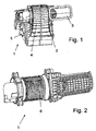
- FIGS. 1 to 3 a fan unit 1 according to the invention is shown according to the embodiment. If not mentioned below, this blower unit 1 corresponds to the previously described blower unit 1 '.
- one intake channel 3 is arranged on one side, in the present case in the motor vehicle on the right.
- the intake passage 3 is formed with a slightly larger cross-section, but this need not necessarily be the case. Rather, the same components for the corresponding intake as for the previously described blower unit 1 can be used.
- a cover in the form of a plastic cap is provided in place of the left intake duct 3 ', which is mounted airtight on the housing 2, so that no air from the vehicle interior can be sucked from the left and sucked from the right air essentially distributed over the entire double-flow impeller 6, ie In the absence of the second intake duct 3 ', the actually double-flow blower is in principle operated in single-flow.
Landscapes
- Physics & Mathematics (AREA)
- Thermal Sciences (AREA)
- Engineering & Computer Science (AREA)
- Mechanical Engineering (AREA)
- Air-Conditioning For Vehicles (AREA)
- Structures Of Non-Positive Displacement Pumps (AREA)
Description
- Die Erfindung betrifft eine Gebläseeinheit, insbesondere für ein Kraftfahrzeug, gemäß dem Oberbegriff des Anspruchs 1.
- Aus der
US 5,111,738 A ist eine Gebläseeinheit bekannt, die für links- und rechtsgelenkte Fahrzeuge verwendet werden kann. Hierbei weist die Gebläseeinheit ein Gehäuse mit einer oberen Wand, einer unteren Wand und zwei einander gegenüberliegende Wände auf, die zusammen zwei offene und einander gegenüberliegende Endflächen mit dem gleichen Profil definieren. Das Gehäuse weist auch einen Montagerahmen mit einem Gebläse auf, das in den Rahmen eingebaut ist. Ferner sind ein Laufrad, ein Gebläsemotor für das Laufrad und zwei symmetrische Halbschalen vorgesehen, die zusammengebaut werden, um ein Spiralgehäuse zu bilden, in dem das Laufrad und der Motor angeordnet sind. Eine derartige Gebläseeinheit ist jedoch in aller Regel nur für einen Fahrzeugtyp geeignet. -
EP 1 420 168 undEP 161 4 564 zeigen ein- und zweiflutige Gebläseeinheiten, die sich jeweils durch ihr Gehäuse unterscheiden. Die zwischenveröffentlichteEP 1 827 213 offenbart ein- und zweiflutige Gebläseeinheiten mit jeweils unterschiedlichen Laufrädern. - Es ist Aufgabe der Erfindung, eine verbesserte Gebläseeinheit zur Verfügung zu stellen.
- Diese Aufgabe wird gelöst durch eine Gebläseeinheit mit den Merkmalen des Anspruchs 1. Vorteilhafte Ausgestaltungen sind Gegenstand der Unteransprüche.
- Erfindungsgemäß ist eine Gebläseeinheit vorgesehen, insbesondere für ein Kraftfahrzeug, mit einem zweiflutigen Laufrad, wobei eine Abdeckung die Öffnung des Ansaugkanals einer Flut beständig verschließt. Die Abdeckung ist als Deckel ausgebildet und an Stelle eines Ansaugkanals am Gehäuse fixiert, bspw. mittels Verclipsen oder mit Schrauben. Durch das Verschließen des einen Ansaugkanals wird die Luft nur über den einzigen vorhandenen Ansaugkanal angesaugt, d.h. die zweiflutige Gebläseeinheit wird im Prinzip nur als einflutige Gebläseeinheit verwendet. Die angesaugte Luft verteilt sich im Gehäuse auf beide Fluten und wird dem Ausblaskanal zugeführt. Eine derartige Gebläseeinheit kann insbesondere für kleinere Kraftfahrzeuge verwendet werden, während die große, mit zwei Ansaugkanälen ausgebildete und zweiflutig betriebene Gebläseeinheit bspw. für Vans verwendet werden kann. Durch die abgesehen vom fehlenden Ansaugkanal im Wesentlichen gleiche Ausgestaltung der Gebläseeinheiten können viele Gleichteile verwendet werden, wodurch die Stückzahlen erhöht und dadurch die Herstellungskosten verringert werden können. Im Falle der einflutig verwendeten Gebläseeinheit lässt sich zudem einfach bei entsprechenden Bauraumbedingungen von Links- auf Rechtslenker umstellen.
- Vorzugsweise entspricht der Ausblaskanal bei einer einflutig verwendeten Gebläseeinheit dem Ausblaskanal einer zweiflutig verwendeten Gebläseeinheit, d.h. im Bereich eines nachfolgenden Heiz- und/oder Klimageräts sind bei entsprechender Ausgestaltung der Gebläseeinheit und ausreichend Bauraum keine Änderungen zwischen einzelnen Varianten erforderlich.
- Der Querschnitt des Ansaugkanals bei einer einflutig verwendeten Gebläseeinheit ist vorzugsweise größer als der Querschnitt eines Ansaugkanals bei einer zweiflutig verwendeten Gebläseeinheit, er kann jedoch auch unverändert sein, so dass weitere Gleichteile möglich sind. Im Falle eines unterschiedlichen Querschnitts ist der Querschnitt der einflutig verwendeten Gebläseeinheit bevorzugt maximal doppelt so groß wie der Querschnitt eines Ansaugkanals bei einer zweiflutig verwendeten Gebläseeinheit, insbesondere ist er 1,2 bis 1,7-mal, besonders bevorzugt 1,5-mal, so groß.
- Die Gebläseeinheit weist vorzugsweise ein mehrteilig ausgebildetes Gehäuse auf Kunststoff auf. Derartige Gehäuse lassen sich kostengünstig herstellen und ermöglichen einen relativ einfachen Ein- und Ausbau des Laufrads und/oder Motors. Insbesondere bevorzugt ist das Gehäuse in der Mittelebene trennbar.
- Bevorzugt wird eine derartige Gebläseeinheit in ihrer zweiflutig benutzten Form in einem Van oder einem anderen, größeren Kraftfahrzeug eingebaut und in ihrer einflutig benutzten Form in einem kleineren Kraftfahrzeug. Dabei kann sie Teil einer Heiz- oder Klimaanlage sein.
- Im Folgenden wird die Erfindung anhand eines Ausführungsbeispiels unter Bezugnahme auf die Zeichnung im Einzelnen erläutert. In der Zeichnung zeigen:
- Fig. 1
- eine perspektivische Ansicht einer Gebläseeinheit mit zweiflutigem Gebläse, das einflutig betrieben wird, gemäß dem Ausführungsbeispiel,
- Fig. 2
- eine Ansicht der Gebläseeinheit von
Fig. 1 ohne Gehäuse, - Fig. 3
- eine Ansicht der Gebläseeinheit von
Fig. 1 von hinten, - Fig. 4
- eine
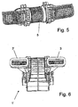
Fig. 1 entsprechende Ansicht der Gebläseeinheit mit einemFig. 1 entsprechenden, zweiflutigen Gebläse, das zweiflutig betrieben wird, - Fig. 5
- eine Ansicht der Gebläseeinheit von
Fig. 4 ohne Gebläse, und - Fig. 6
- eine Ansicht der Gebläseeinheit von
Fig. 4 von hinten. - Um die Erfindung besser verständlich zu machen, wird im Folgenden zuerst der Aufbau einer Gebläseeinheit 1' einer Kraftfahrzeug-Klimaanlage mit nachfolgend der Gebläseeinheit 1' angeordnetem Verdampfer und Heizer und einer Mehrzahl von die temperierte Luft dem Fahrzeuginnenraum zuführenden Luftkanälen beschrieben, die in einem Van verwendet wird. Der Aufbau der Klimaanlage per se entspricht dem einer herkömmlichen Klimaanlage und wird daher im Folgenden nicht näher beschrieben.
- Die Gebläseeinheit 1' weist ein mehrteilig ausgebildetes Gehäuse 2 aus Kunststoff mit zwei Ansaugkanälen 3 und 3', einem zweiteiligen Spiralteil 4 und einem Ausblaskanal 5, ein auf einer Welle angeordnetes, zweiflutiges Laufrad 6 aus Kunststoff und einen Antriebsmotor auf. Die Ansaugkanäle 3 sind rechts und links des Laufrades 6 angeordnet, so dass mit Hilfe des sich drehenden zweiflutigen Laufrads 6 von beiden Seiten Luft angesaugt und in den Ausblaskanal 5 geschoben wird. Der Aufbau der Gebläseeinheit 1' ist im Wesentlichen spiegelbildlich zur Mittelebene, welche zwischen den beiden Fluten verläuft. Der Aufbau der Gebläseeinheit 1' entspricht im Wesentlichen dem einer herkömmlichen zweiflutigen Gebläseeinheit.
- In den
Figuren 1 bis 3 ist eine erfindungsgemäße Gebläseeinheit 1 gemäß dem Ausführungsbeispiel dargestellt. Diese Gebläseeinheit 1 entspricht sofern nachfolgend nicht erwähnt der zuvor beschriebenen Gebläseeinheit 1'. - Sie weist ein mehrteilig ausgebildetes Gehäuse 2 mit - im Unterschied zur zuvor beschriebenen Gebläseeinheit 1' - nur einem Ansaugkanal 3, einem zweiteiligen Spiralteil 4 und einem Ausblaskanal 5, ein auf einer Welle angeordnetes, zweiflutiges Laufrad 6 und einen Antriebsmotor auf. Wie aus der Zeichnung ersichtlich, ist der eine Ansaugkanal 3 auf einer Seite, vorliegend im Kraftfahrzeug rechts, angeordnet.
- Um einen ausreichenden Luftmassestrom zu erreichen, ist der Ansaugkanal 3 mit einem etwas größeren Querschnitt ausgebildet, jedoch muss dies nicht notwendigerweise der Fall sein. Vielmehr können auch die selben Bauteile für den entsprechenden Ansaugbereich wie für die zuvor beschriebene Gebläseeinheit 1 verwendet werden.
- Im Unterschied zur zuvor beschriebenen Gebläseeinheit 1 ist an Stelle des linken Ansaugkanals 3' eine Abdeckung in Form einer Kunststoffkappe vorgesehen, die am Gehäuse 2 luftdicht angebracht ist, so dass von links her keine Luft aus dem Fahrzeuginnenraum angesaugt werden kann und die von rechts angesaugte Luft sich im Wesentlichen über das gesamte zweiflutige Laufrad 6 verteilt, d.h. mangels des zweiten Ansaugkanals 3' wird das eigentlich zweiflutig ausgebildete Gebläse im Prinzip einflutig betrieben.
Claims (8)
- Ein- und zweiflutig betreibbare Gebläseeinheit (1, 1'), insbesondere für ein Kraftfahrzeug, mit einem zweiflutigen Laufrad (6), einem Ausblaskanal (5) und in einem Gehäuse (2) ausgebildeten Öffnungen für zwei Ansaugkanäle (3, 3'), dadurch gekennzeichnet, dass bei einflutigem Betrieb eine als Deckel ausgebildete Abdeckung am Gehäuse (2) fixiert ist und die Öffnung für einen der Ansaugkanäle (3') beständig verschließt.
- Gebläseeinheit nach Anspruch 1, dadurch gekennzeichnet, dass der für einflutigen Betrieb vorgesehene Ausblaskanal (5) dem für zweiflutigen Betrieb vorgesehenen entspricht.
- Gebläseeinheit nach Anspruch 1 oder 2, dadurch gekennzeichnet, dass bei einflutigem Betrieb zwei für zweiflutigen Betrieb vorgesehene Ansaugkanäle (3, 3') durch einen Ansaugkanal (3) gleichen oder größeren Querschnitts ersetzt sind.
- Gebläseeinheit nach Anspruch 3, dadurch gekennzeichnet, dass der Querschnitt des für einflutigen Betrieb vorgesehenen Ansaugkanals (3) maximal doppelt so groß wie der Querschnitt eines der für zweiflutigen Betrieb vorgesehenen Ansaugkanäle (3, 3') ist.
- Gebläseeinheit nach einem der vorhergehenden Ansprüche, dadurch gekennzeichnet, dass das Gehäuse (2) auf Kunststoff und mehrteilig ausgebildet ist.
- Gebläseeinheit nach einem der vorhergehenden Ansprüche, dadurch gekennzeichnet, dass das Gehäuse (2) zumindest in der Mittelebene trennbar ist.
- Kraftfahrzeug-Klimaanlage mit einer Gebläseeinheit (1) nach einem der Ansprüche 1 bis 6.
- Verwendung einer zweiflutig betriebenen Gebläseeinheit (1') nach einem der Ansprüche 1 bis 6 in einem Van oder einem anderen, größeren Kraftfahrzeug und einer einflutig betriebenen Gebläseeinheit (1) nach einem der Ansprüche 1 bis 6 in einem kleineren Kraftfahrzeug.
Priority Applications (2)
| Application Number | Priority Date | Filing Date | Title |
|---|---|---|---|
| DE200650004679 DE502006004679D1 (de) | 2006-10-05 | 2006-10-05 | Gebläseeinheit, insbesondere für ein Kraftfahrzeug |
| EP20060291558 EP1908613B1 (de) | 2006-10-05 | 2006-10-05 | Gebläseeinheit, insbesondere für ein Kraftfahrzeug |
Applications Claiming Priority (1)
| Application Number | Priority Date | Filing Date | Title |
|---|---|---|---|
| EP20060291558 EP1908613B1 (de) | 2006-10-05 | 2006-10-05 | Gebläseeinheit, insbesondere für ein Kraftfahrzeug |
Publications (2)
| Publication Number | Publication Date |
|---|---|
| EP1908613A1 EP1908613A1 (de) | 2008-04-09 |
| EP1908613B1 true EP1908613B1 (de) | 2009-08-26 |
Family
ID=37831481
Family Applications (1)
| Application Number | Title | Priority Date | Filing Date |
|---|---|---|---|
| EP20060291558 Ceased EP1908613B1 (de) | 2006-10-05 | 2006-10-05 | Gebläseeinheit, insbesondere für ein Kraftfahrzeug |
Country Status (2)
| Country | Link |
|---|---|
| EP (1) | EP1908613B1 (de) |
| DE (1) | DE502006004679D1 (de) |
Family Cites Families (4)
| Publication number | Priority date | Publication date | Assignee | Title |
|---|---|---|---|---|
| US1978459A (en) * | 1932-05-31 | 1934-10-30 | American Air Filter Co | Fan or blower housing |
| DE3224560A1 (de) * | 1982-07-01 | 1984-01-05 | Süddeutsche Kühlerfabrik Julius Fr. Behr GmbH & Co KG, 7000 Stuttgart | Klimaanlage fuer ein kraftfahrzeug |
| DE19908501A1 (de) * | 1999-02-26 | 2000-03-30 | Daimler Chrysler Ag | Radialgebläse |
| JP4722555B2 (ja) * | 2004-07-09 | 2011-07-13 | サンデン株式会社 | 遠心式送風機 |
-
2006
- 2006-10-05 DE DE200650004679 patent/DE502006004679D1/de active Active
- 2006-10-05 EP EP20060291558 patent/EP1908613B1/de not_active Ceased
Also Published As
| Publication number | Publication date |
|---|---|
| EP1908613A1 (de) | 2008-04-09 |
| DE502006004679D1 (de) | 2009-10-08 |
Similar Documents
| Publication | Publication Date | Title |
|---|---|---|
| DE102011051489B4 (de) | Gebläse-Luftansaugungsvorrichtung | |
| DE69102127T2 (de) | Lüfter, insbesondere für Kraftfahrzeuge. | |
| CH669431A5 (de) | ||
| WO2017167584A1 (de) | Vakuumpumpe mit schalldämpfung | |
| EP1902220B1 (de) | Laufrad | |
| DE2939385C2 (de) | Radialgebläse, insbesondere für Heiz- oder Klimaanlagen von Fahrzeugen | |
| DE102018211809A1 (de) | Gehäuse für einen Ventilator und Ventilator | |
| EP2275687A2 (de) | Radiallüftergehäuse | |
| DE102020200363A1 (de) | Tragmodul für einen Ventilator und Ventilator mit einem entsprechenden Tragmodul | |
| EP2000337A2 (de) | Gebläseanordnung zur Belüftung eines Fahrzeugs | |
| DE102011011975A1 (de) | Luftansaugvorrichtung einer Fahrzeuginnenraumbelüftungsanlage und Fahrzeuginnenraumbelüftungsanlage | |
| DE602006000387T2 (de) | Doppelgebläseanordnung für Kraftfahrzeuge | |
| EP1908613B1 (de) | Gebläseeinheit, insbesondere für ein Kraftfahrzeug | |
| DE60306733T2 (de) | Radiallüfter | |
| AT394434B (de) | Geblaeseanordnung | |
| DE3740132C2 (de) | ||
| DE1924611A1 (de) | Geblaese | |
| DE102005016820A1 (de) | Großmotor | |
| DE4241804C2 (de) | Tandemlüfter für Kraftfahrzeuge | |
| EP2080910B1 (de) | Gebläse, insbesondere Fahrzeuggebläse | |
| DE102010002658A1 (de) | Gebläsemodul | |
| DE102008010182A1 (de) | Gehäuse für eine Gasfördereinrichtung | |
| DE3905092C2 (de) | ||
| EP1717070B1 (de) | Lüftungsvorrichtung, insbesondere für ein Kraftfahrzeug | |
| EP1247667B1 (de) | Strömungsklappe |
Legal Events
| Date | Code | Title | Description |
|---|---|---|---|
| PUAI | Public reference made under article 153(3) epc to a published international application that has entered the european phase |
Free format text: ORIGINAL CODE: 0009012 |
|
| AK | Designated contracting states |
Kind code of ref document: A1 Designated state(s): AT BE BG CH CY CZ DE DK EE ES FI FR GB GR HU IE IS IT LI LT LU LV MC NL PL PT RO SE SI SK TR |
|
| AX | Request for extension of the european patent |
Extension state: AL BA HR MK RS |
|
| 17P | Request for examination filed |
Effective date: 20081009 |
|
| 17Q | First examination report despatched |
Effective date: 20081106 |
|
| AKX | Designation fees paid |
Designated state(s): DE FR GB |
|
| GRAP | Despatch of communication of intention to grant a patent |
Free format text: ORIGINAL CODE: EPIDOSNIGR1 |
|
| GRAS | Grant fee paid |
Free format text: ORIGINAL CODE: EPIDOSNIGR3 |
|
| GRAA | (expected) grant |
Free format text: ORIGINAL CODE: 0009210 |
|
| AK | Designated contracting states |
Kind code of ref document: B1 Designated state(s): DE FR GB |
|
| REG | Reference to a national code |
Ref country code: GB Ref legal event code: FG4D Free format text: NOT ENGLISH |
|
| REF | Corresponds to: |
Ref document number: 502006004679 Country of ref document: DE Date of ref document: 20091008 Kind code of ref document: P |
|
| PLBE | No opposition filed within time limit |
Free format text: ORIGINAL CODE: 0009261 |
|
| STAA | Information on the status of an ep patent application or granted ep patent |
Free format text: STATUS: NO OPPOSITION FILED WITHIN TIME LIMIT |
|
| 26N | No opposition filed |
Effective date: 20100527 |
|
| PGFP | Annual fee paid to national office [announced via postgrant information from national office to epo] |
Ref country code: GB Payment date: 20101025 Year of fee payment: 5 |
|
| GBPC | Gb: european patent ceased through non-payment of renewal fee |
Effective date: 20121005 |
|
| PG25 | Lapsed in a contracting state [announced via postgrant information from national office to epo] |
Ref country code: GB Free format text: LAPSE BECAUSE OF NON-PAYMENT OF DUE FEES Effective date: 20121005 |
|
| REG | Reference to a national code |
Ref country code: DE Ref legal event code: R082 Ref document number: 502006004679 Country of ref document: DE Representative=s name: GRAUEL, ANDREAS, DIPL.-PHYS. DR. RER. NAT., DE Ref country code: DE Ref legal event code: R081 Ref document number: 502006004679 Country of ref document: DE Owner name: MAHLE INTERNATIONAL GMBH, DE Free format text: FORMER OWNER: BEHR FRANCE ROUFFACH S.A.S., ROUFFACH, FR |
|
| REG | Reference to a national code |
Ref country code: FR Ref legal event code: PLFP Year of fee payment: 10 |
|
| REG | Reference to a national code |
Ref country code: FR Ref legal event code: PLFP Year of fee payment: 11 |
|
| REG | Reference to a national code |
Ref country code: FR Ref legal event code: PLFP Year of fee payment: 12 |
|
| REG | Reference to a national code |
Ref country code: FR Ref legal event code: PLFP Year of fee payment: 13 |
|
| PGFP | Annual fee paid to national office [announced via postgrant information from national office to epo] |
Ref country code: DE Payment date: 20181030 Year of fee payment: 13 |
|
| REG | Reference to a national code |
Ref country code: DE Ref legal event code: R119 Ref document number: 502006004679 Country of ref document: DE |
|
| PG25 | Lapsed in a contracting state [announced via postgrant information from national office to epo] |
Ref country code: DE Free format text: LAPSE BECAUSE OF NON-PAYMENT OF DUE FEES Effective date: 20200501 |
|
| PGFP | Annual fee paid to national office [announced via postgrant information from national office to epo] |
Ref country code: FR Payment date: 20201023 Year of fee payment: 15 |
|
| PG25 | Lapsed in a contracting state [announced via postgrant information from national office to epo] |
Ref country code: FR Free format text: LAPSE BECAUSE OF NON-PAYMENT OF DUE FEES Effective date: 20211031 |