EP1614564A2 - Centrifugal blower - Google Patents
Centrifugal blower Download PDFInfo
- Publication number
- EP1614564A2 EP1614564A2 EP05254152A EP05254152A EP1614564A2 EP 1614564 A2 EP1614564 A2 EP 1614564A2 EP 05254152 A EP05254152 A EP 05254152A EP 05254152 A EP05254152 A EP 05254152A EP 1614564 A2 EP1614564 A2 EP 1614564A2
- Authority
- EP
- European Patent Office
- Prior art keywords
- air
- motor
- cover
- centrifugal blower
- casing
- Prior art date
- Legal status (The legal status is an assumption and is not a legal conclusion. Google has not performed a legal analysis and makes no representation as to the accuracy of the status listed.)
- Granted
Links
Images


Classifications
-
- B—PERFORMING OPERATIONS; TRANSPORTING
- B60—VEHICLES IN GENERAL
- B60H—ARRANGEMENTS OF HEATING, COOLING, VENTILATING OR OTHER AIR-TREATING DEVICES SPECIALLY ADAPTED FOR PASSENGER OR GOODS SPACES OF VEHICLES
- B60H1/00—Heating, cooling or ventilating devices
- B60H1/00457—Ventilation unit, e.g. combined with a radiator
- B60H1/00471—The ventilator being of the radial type, i.e. with radial expulsion of the air
Definitions
- the present invention relates to a centrifugal blower, and, more specifically, to a double-axis type centrifugal multiblade blower suitable particularly for use in an air conditioning system for vehicles.
- a conventional blower used in an air conditioning system for vehicles in particular, as a blower for a thin air conditioning unit mounted in a cabin of a work vehicle at a position of a space between an operator seat and a floor and the like, known is a double-axis type blower which has multiblade fans connected to respective rotary shafts of a double-axis type motor and casings the interior of each of which is formed as a scroll structure.
- air intake is carried out in both the fans, and a design device so as not to damage the air intake when the blower is mounted, for example, a design device to provide a bellmouth having a diameter increasing toward an outside of each casing to an air intake port of each casing, is carried out, as disclosed in, for example, JP-A-2004-169579.
- the following problems may be considered as to motor cooling of a double-axis type centrifugal multiblade blower.
- the motor cooling of a double-axis type centrifugal multiblade blower is carried out by utilizing a static pressure in an air conditioning unit or a pressure difference between a static pressure in a blower casing and a static pressure in a blower motor. Therefore, accessories such as pipes or hoses for introducing cooling air into a motor are required. Further, in the air sending from an air conditioning unit, for example, a care is required for preventing water adhered to an evaporator from entering into the motor through a certain route.
- the life span of the blower motor depends on a temperature of a brush in the motor, and in a case where the brush temperature at the time of motor driving is high, the life span may decrease.
- a centrifugal blower comprises first and second multiblade fans each connected to each rotary shaft of a double-axis type motor, first and second casings each containing each of the first and second multiblade fans, an interior of each of the first and second casings being formed as a scroll structure, and a cover for covering both of the first and second casings.
- the centrifugal blower is characterized in that the cover has an opening only at a position corresponding to a position of an air intake port of the first casing except at positions corresponding to positions of air discharge ports of both of the first and second casings.
- the blower is designed initially as an one-side air intake structure, and the aforementioned problems accompanying with the one-side air intake are to be solved by improving the inside structure of the centrifugal blower.
- a portion of the scroll-structure interior of the first casing positioned at an air discharge port side of the first casing is formed as a two-layer scroll structure, and a part of discharged air separated by the two-layer scroll structure is introduced into the cover. Further, it is preferred that a guide for guiding the part of discharged air separated by the two-layer scroll structure to an air intake port of the second casing is provided in the cover.
- a main plate of the second multiblade fan connecting a multiblade fan portion of the second multiblade fan to the rotary shaft is disposed at a position in an outer half area in an axial direction of the second multiblade fan.
- the scroll in the air-intake side fan (in the first multiblade fan) is formed as a two-layer scroll structure (a double-scroll structure) so that a part of the air discharged from the first multiblade fan of the air-intake side can be sent to the non-air-intake side fan (the second multiblade fan), and in the side of the non-air-intake side fan (the second multiblade fan), the main plate is disposed at a position of an outer side in the axial direction so that the air intake path can be enlarged in order to efficiently suck the air sent from the side of the first multiblade fan into the second multiblade fan.
- a bellmouth having a diameter increasing toward an outside of each casing is provided to an air intake port of each casing, in order to suck air more smoothly.
- a motor cooling air guide for guiding the part of discharged air separated by the two-layer scroll structure to the motor as motor cooling air is provided in the cover.
- the motor cooling air is guided to a cooling air intake port provided on the motor or a motor cover, and therefrom, the motor cooling air is introduced into the motor.
- This motor cooling air guide may be provided integrally with the above-described cover, or may be provided integrally with the motor cover separated from the above-described cover.
- the cooling air may be efficiently supplied into the motor without using many parts for introducing cooling air.
- a centrifugal blower 1 is constructed as a blower used in an air conditioning system for vehicles, particularly, for work vehicles.
- centrifugal blower 1 is used as a blower mounted, for example, at a position of a space between an operator seat and a floor in a cabin of a work vehicle for a thin-type air conditioning unit, and is used for sending air to a heat exchanger, for example, an evaporator of refrigerant.
- centrifugal blower 1 has a double-axis type motor 2, first multiblade fan 5 and second multiblade fan 6 connected, respectively, to rotary shafts 3 and 4 of double-axis type motor 2.
- First and second multiblade fans 5 and 6 are contained in first and second casings 7 and 8, respectively, and the interior of each of casings 7 and 8 is formed as a scroll structure.
- the whole of motor 2, first and second multiblade fans 5 and 6 and first and second casings 7 and 8 are covered with a blower cover 9.
- This cover 9 has an opening 12 only at a position corresponding to a position of an air intake port 11 of first casing 7 as an air intake opening except at positions corresponding to positions of air discharge ports of both of first and second casings 7 and 8.
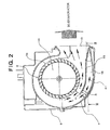
- an air discharge port 10 of first casing 7 for first multiblade fan 5 is depicted in Fig. 2.
- multiblade fan portion 5a is formed by arranging curved blades in the circumferential direction, and by rotating multiblade fan portion 5a, air sucked into the inside is sent along the scroll shape of first casing 7, and discharged from air discharge port 10.
- Multiblade fan portion 5a and motor rotary shaft 3 are connected to each other by a main plate 13, thereby transmitting the driving force of motor 2 from rotary shaft 3 to multiblade fan portion 5a through main plate 13.
- second multiblade fan 6 which is a non-air intake side fan, has a similar motor driving force transmitting structure, in second multiblade fan 6, as depicted in Fig. 1, a main plate 14 connected to motor rotary shaft 4 is disposed at a position in an outer half area in the axial direction of second multiblade fan 6.
- a partition 15 is provided at a position of air discharge port 10 in the scroll of first casing 7 for first multiblade fan 5, and by this partition 15, the scroll-structure interior of first casing 7 is formed as a two-layer scroll structure (a double scroll structure).
- a radially outer-side scroll portion 16 has a flow path formed so as to discharge a part of discharged air (outer side air) separated by the two-layer scroll structure into cover 9 without guiding the air to air discharge port 10, as depicted in Figs. 1 to 3.
- this part of discharged air is discharged toward the side of an air intake port 17 of second casing 8 for second multiblade fan 6.
- a guide 18 for guiding this part of discharged air to air intake port 17 of second casing 8 for second multiblade fan 6 is provided in cover 9. Therefore, discharged air Al of first multiblade fan 5 guided through outer-side scroll portion 16 formed by partition 15 becomes at least a part of air supplied to second multiblade fan 6, as shown in Figs. 1 and 2.
- second multiblade fan 6 can suck other air such as air A2 bypassing first multiblade fan 5.
- the amount of the above-described air supplied to second multiblade fan 6 through outer-side scroll portion 16 can be appropriately controlled by adjusting the height h of the flow path of the outer-side scroll portion 16 formed by partition 15.
- the amount of air supplied to second multiblade fan 6 among the total amount of air discharged by first multiblade fan 6 can be controlled, and therefore, the air sending balance of the entire centrifugal blower 1 can be improved more preferably.
- a bellmouth 19 having a diameter increasing toward an outside of each of first and second casings 7 and 8 is provided to each of air intake ports 11 and 17 of first and second casings 7 and 8.
- centrifugal blower 1 thus constructed, since opening 12 is provided only at a position of one side of cover 9, a one-side air intake is intentionally formed.
- the air sucked from air intake port 11 of first multiblade fan 5 disposed in this side is accelerated in the scroll of first casing 7 for the first multiblade fan 5, and discharged from air discharge port 10.
- the interior of the scroll of first casing 7 is formed as a two-layer scroll structure, a part of the air flowing in the scroll, which is separated by the two-layer scroll structure, is supplied to air intake port 17 of second casing 8 for second multiblade fan 6.
- second multiblade fan 6 lack of air intake is prevented by this supplied air even if a particular air intake route is not ensured, it becomes possible to make the amount of air sending by first multiblade fan 5 and the amount of air sending by second multiblade fan 6 to be about equal, and therefore, the air sending balance between first and second multiblade fans 5 and 6 may be improved. Namely, it becomes possible to intentionally form a one-side air intake and to ensure a good air sending balance between first and second multiblade fans 5 and 6.
- the air discharged from centrifugal blower 1 is used, for example, as air sent to an evaporator for refrigerant in an air conditioning system, as aforementioned. Therefore, air sending balance of the discharged air from centrifugal blower 1 can be evaluated by measurement of surface temperature on the evaporator.
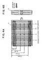
- Fig. 4A is an elevational view of evaporator 21, and Fig. 4B is a side view thereof, and the air discharged from centrifugal blower 1 was supplied toward one surface of evaporator 21.
- Fig. 4A various measurement positions are shown, and the measurement positions were set by employing the number of stacked tube elements from the left side of evaporator 21 depicted in Fig. 4A (number: 6, 12. 18 and 23) and dimensions from the upper end of evaporator 21 depicted in Fig. 4A (dimension: 45 mm, 85 mm, 125 mm and 170 mm).
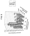
- Fig. 5 shows the result of the above-described evaluation as to the measurement of the surface temperatures of evaporator 21 in a case where the structure specified in Figs. 1 to 3 was not provided, in particular, a structure wherein an opening was provided only at one side of cover 9 and a structure wherein a part of air discharged from first multiblade fan 5 was supplied toward air intake port 17 of second casing 8 for second multiblade fan 6 were not provided.
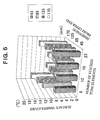
- Fig. 6 shows the result of the above-described evaluation as to the measurement of the surface temperatures of evaporator 21 in a case where the structure according to the present invention was applied. From the comparison between the results shown in Figs. 5 and 6, it is understood that the air sending balance was explicitly improved by application of the present invention.
- Fig. 7 depicts a centrifugal blower 31 according to a second embodiment of the present invention.
- a part of the air which is separated by the two-layer scroll structure formed by partition 15 as a part of air discharged from first multiblade fan 5 and led toward second multiblade fan 6, is guided motor 2 as motor cooling air by a motor cooling air guide 32 provided on the way of the air path from first multiblade fan 5 to second multiblade fan 6.
- motor cooling air guide 32 is provided integrally with blower cover 9 in the cover 9, it may be provided integrally with a motor cover which covers motor 2 itself.
- motor cooling air guide 32 can be adjusted in length, and the distribution between the amount of air supplied to second multiblade fan 6 and the amount of air used as motor cooling air can be easily controlled.
- the air guided by motor cooling air guide 32 is introduced into motor 2 through a cooling air intake port 33 provided on motor 2, and the introduced air cools various portions in the motor 2 (for example, brush portions and bearing portions).
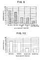
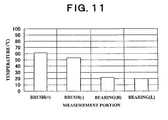
- Figs. 8 and 9 show the results of temperature measurement on brush portions (plus (+) side and minus (-) side brush portions) and bearing portions (right (R) side and left (L) side bearing portions) in motor 2 in a case where motor cooling air guide 32 was not provided (Fig. 8) and in a case where motor cooling air guide 32 was provided (Fig. 9). Since the outside air temperatures at the times of the measurement shown in Fig. 8 and the measurement shown in Fig. 9 were slightly different from each other, only the amounts of temperature elevation calculated by subtracting the respective outside air temperatures from the brush or bearing portion temperature shown in Figs. 8 and 9 are shown in Figs. 10 and 11. Fig. 10 shows the case where motor cooling air guide 32 was not provided, and Fig. 11 shows the case where motor cooling air guide 32 was provided.
- centrifugal blower is useful for a case where only one side space can be ensured for air intake, for example, as a blower for an air conditioning system for work vehicles, which is disposed in a cabin of a work vehicle.
Landscapes
- Physics & Mathematics (AREA)
- Thermal Sciences (AREA)
- Engineering & Computer Science (AREA)
- Mechanical Engineering (AREA)
- Structures Of Non-Positive Displacement Pumps (AREA)
Abstract
Description
- The present invention relates to a centrifugal blower, and, more specifically, to a double-axis type centrifugal multiblade blower suitable particularly for use in an air conditioning system for vehicles.
- As a conventional blower used in an air conditioning system for vehicles, in particular, as a blower for a thin air conditioning unit mounted in a cabin of a work vehicle at a position of a space between an operator seat and a floor and the like, known is a double-axis type blower which has multiblade fans connected to respective rotary shafts of a double-axis type motor and casings the interior of each of which is formed as a scroll structure. In such a double-axis type blower, air intake is carried out in both the fans, and a design device so as not to damage the air intake when the blower is mounted, for example, a design device to provide a bellmouth having a diameter increasing toward an outside of each casing to an air intake port of each casing, is carried out, as disclosed in, for example, JP-A-2004-169579.
- In a recent work vehicle, for the purpose of increasing the comfortability in a cabin, a space for mounting an air conditioning unit is restricted smaller, and it has been difficult to ensure a sufficiently large space for air intake of a blower. Depending upon a mounting condition, there may be a case where a double-axis type blower can suck air only from a fan of one side. However, in such a case where air intake is carried out only at one side fan of the double-axis type blower, the ability for sending air may be reduced and at the same time more air is supplied to the fan of the air-intake side, and therefore, the air sending balance between both fans may be broken remarkably. The unbalanced air sending may disturb a temperature distribution of a heat exchanger, and as a result, the ability of the heat exchanger may not be exhibited sufficiently, thereby reducing the cooling ability of the air conditioning unit remarkably.
- In order to solve such a problem, it is considered to ensure an air intake route for a fan of smaller air intake amount side. In such a structure, however, although the air sending balance may be improved to some extent, the size of the entire unit becomes large, and it becomes difficult to dispose the unit within a limited mounting space.
- Further, the following problems may be considered as to motor cooling of a double-axis type centrifugal multiblade blower. Namely, in a conventional technology, the motor cooling of a double-axis type centrifugal multiblade blower is carried out by utilizing a static pressure in an air conditioning unit or a pressure difference between a static pressure in a blower casing and a static pressure in a blower motor. Therefore, accessories such as pipes or hoses for introducing cooling air into a motor are required. Further, in the air sending from an air conditioning unit, for example, a care is required for preventing water adhered to an evaporator from entering into the motor through a certain route.
- Furthermore, because a space for mounting an air conditioning unit is restricted smaller for the purpose of increasing the comfortability in a cabin in a recent work vehicle, as aforementioned, depending upon the mounting condition, there is a case where air is sent from a blower disposed outside of the cabin to a main body (part for functioning as an air conditioner) of the air conditioning unit disposed in the cabin through a hole opened on a wall surface. In such a case, for cooling a double-axis type motor, it is required to send cooling air into the motor from the main body of the air conditioning unit by using a pipe provided through the exclusive hole opened on the wall surface, and therefore, an exclusive pipe and a seal (a packing) for preventing air leakage are required. Further, similarly to the above-described case, a care is required for preventing water adhered to an evaporator from entering into the motor. The life span of the blower motor depends on a temperature of a brush in the motor, and in a case where the brush temperature at the time of motor driving is high, the life span may decrease.
- It would be desirable to provide a double-axis type centrifugal multiblade blower which can improve the reduction of the ability for air sending and the unbalanced air sending of a double-axis type blower in a case of one side air intake, without changing the size of the entire blower, and which can prevent reduction of the cooling ability of the air conditioning unit.
- Further, it would be desirable to provide a double-axis type centrifugal multiblade blower which can effectively cool a blower motor while decreasing the number of parts and which can extend the life span by suppressing elevation of the brush temperature of the motor.
- A centrifugal blower according to the present invention comprises first and second multiblade fans each connected to each rotary shaft of a double-axis type motor, first and second casings each containing each of the first and second multiblade fans, an interior of each of the first and second casings being formed as a scroll structure, and a cover for covering both of the first and second casings. The centrifugal blower is characterized in that the cover has an opening only at a position corresponding to a position of an air intake port of the first casing except at positions corresponding to positions of air discharge ports of both of the first and second casings.
- Namely, by providing an opening only at a position corresponding to a position of an air intake port of the first casing, the blower is designed initially as an one-side air intake structure, and the aforementioned problems accompanying with the one-side air intake are to be solved by improving the inside structure of the centrifugal blower.
- In the centrifugal blower according to the present invention, it is preferred that a portion of the scroll-structure interior of the first casing positioned at an air discharge port side of the first casing is formed as a two-layer scroll structure, and a part of discharged air separated by the two-layer scroll structure is introduced into the cover. Further, it is preferred that a guide for guiding the part of discharged air separated by the two-layer scroll structure to an air intake port of the second casing is provided in the cover.
- Further, in the centrifugal blower, it is preferred that a main plate of the second multiblade fan connecting a multiblade fan portion of the second multiblade fan to the rotary shaft is disposed at a position in an outer half area in an axial direction of the second multiblade fan.
- Namely, the scroll in the air-intake side fan (in the first multiblade fan) is formed as a two-layer scroll structure (a double-scroll structure) so that a part of the air discharged from the first multiblade fan of the air-intake side can be sent to the non-air-intake side fan (the second multiblade fan), and in the side of the non-air-intake side fan (the second multiblade fan), the main plate is disposed at a position of an outer side in the axial direction so that the air intake path can be enlarged in order to efficiently suck the air sent from the side of the first multiblade fan into the second multiblade fan.
- Further, in the centrifugal blower, it is preferred that a bellmouth having a diameter increasing toward an outside of each casing is provided to an air intake port of each casing, in order to suck air more smoothly.
- Further, in the centrifugal blower, it is preferred that a motor cooling air guide for guiding the part of discharged air separated by the two-layer scroll structure to the motor as motor cooling air is provided in the cover. The motor cooling air is guided to a cooling air intake port provided on the motor or a motor cover, and therefrom, the motor cooling air is introduced into the motor. This motor cooling air guide may be provided integrally with the above-described cover, or may be provided integrally with the motor cover separated from the above-described cover.
- In such a centrifugal blower according to the present invention, outside air is sucked from the intake port of the first casing for the first multiblade fan through the opening provided on the cover, and the sucked air is accelerated in the scroll by the first multiblade fan and is discharged through the discharge port of the first casing. A part of this discharged air is used as air supplied to the other fan (the second multiblade fan). In particular, the air is separated by the two-layer scroll structure formed in the first casing, and for example, the radially outer-side air among the separated air flows is sent into the cover and supplied to the air intake port of the other fan (the second multiblade fan). By this supplied air, even if an air intake route for the second multiblade fan is not formed particularly, a lack of air intake of the second multiblade fan may be avoided. As a result, it becomes possible to balance the amounts of air for both fans, and balanced air sending for the double-axis type centrifugal blower can be achieved.
- Further, by providing a motor cooling air guide in the air supplying route to the second multiblade fan, the cooling air may be efficiently supplied into the motor without using many parts for introducing cooling air.
- Thus, in the centrifugal blower according to the present invention, the following advantages can be obtained.
- (1) The air sending balance at the time of one-side air intake in the double-axis type centrifugal blower can be improved, and the temperature distribution in a heat exchanger, which is an object of the air sending, can be stabilized at a desirable temperature distribution.
- (2) The one-side air intake structure can be achieved without any problem, and the design freedom for mounting the blower in a cabin can be remarkably increased. As a result, the freedom of the inside of a vehicle, in particular, a work vehicle, can be increased, and the comfortability in the cabin can be greatly increased.
- (3) Because the cover containing the fan unit interrupts the noise of the blower, reduction of the noise may be achieved.
- (4) Because it is not necessary to particularly ensure an air intake route for the second multiblade fan which is disposed at a position opposite to the side provided with an opening of the cover, the size of the entire blower may be made small.
- (5) Since a cover is provided at least for a motor rotational portion even in a conventional structure, if this cover is formed as the cover according to the present invention, it is possible to achieve the structure according to the present invention substantially without increasing the number of parts. Further, because it is possible to form at least a part of the scroll of the first casing by the cover containing the entire fan unit, also from this point of view, the structure according to the present invention may be achieved without increasing the number of parts, as compared with a conventional structure.
- (6) By providing the motor cooling air guide, it becomes possible to effectively cool the motor without providing an exclusive pipe and seal mechanism thereof for introducing the cooling air, and the number of parts for cooling the motor can also be decreased.
- (7) Further, with respect to motor cooling, it is not necessary to consider the invasion of water from an evaporator and the like, and the maintenance workability may be improved.
- (8) Furthermore, by adjusting the length and the like of the motor cooling air guide, the amount of air supplied to the second multiblade fan and the amount of air used for motor cooling may be distributed easily and appropriately.
- Further features and advantages of the present invention will be understood from the following detailed description of the preferred embodiments of the present invention with reference to the accompanying figures, of which:
- Fig. 1 is a schematic vertical sectional view of a centrifugal blower according to a first embodiment of the present invention.
- Fig. 2 is an enlarged vertical sectional view of the centrifugal blower depicted in Fig. 1, as viewed along II-II line of Fig. 1.
- Fig. 3 is a cross-sectional view of the centrifugal blower depicted in Fig. 2, as viewed along III-III line of Fig. 2.
- Fig. 4A is an elevational view of an evaporator used in a test for determining the performance of the centrifugal blower depicted in Fig. 1, and Fig. 4B is a side view of the evaporator.
- Fig. 5 is a graph showing the distribution of surface temperatures of the evaporator in a performance determination test applying a conventional blower structure.
- Fig. 6 is a graph showing the distribution of surface temperatures of the evaporator in a performance determination test applying the blower structure according to the present invention.
- Fig. 7 is a schematic vertical sectional view of a centrifugal blower according to a second embodiment of the present invention.
- Fig. 8 is a graph showing measured temperatures of various measurement portions in a case where a motor cooling air guide is not provided in the blower depicted in Fig. 7.
- Fig. 9 is a graph showing measured temperatures of various measurement portions in a case where a motor cooling air guide is provided in the blower depicted in Fig. 7.
- Fig. 10 is a graph showing elevated temperatures of various measurement portions in the motor which are calculated by subtracting the outside air temperature from the measured temperatures shown in Fig. 8.
- Fig. 11 is a graph showing elevated temperatures of various measurement portions in the motor which are calculated by subtracting the outside air temperature from the measured temperatures shown in Fig. 9.
- Figs. 1 to 3 depict a centrifugal blower according to a first embodiment of the present invention. In this embodiment, a
centrifugal blower 1 is constructed as a blower used in an air conditioning system for vehicles, particularly, for work vehicles. For example,centrifugal blower 1 is used as a blower mounted, for example, at a position of a space between an operator seat and a floor in a cabin of a work vehicle for a thin-type air conditioning unit, and is used for sending air to a heat exchanger, for example, an evaporator of refrigerant. - As depicted in Fig. 1,
centrifugal blower 1 has a double-axis type motor 2,first multiblade fan 5 andsecond multiblade fan 6 connected, respectively, torotary shafts axis type motor 2. First and secondmultiblade fans second casings casings motor 2, first and secondmultiblade fans second casings blower cover 9. Thiscover 9 has anopening 12 only at a position corresponding to a position of anair intake port 11 offirst casing 7 as an air intake opening except at positions corresponding to positions of air discharge ports of both of first andsecond casings air discharge port 10 offirst casing 7 for firstmultiblade fan 5 is depicted in Fig. 2. - In respective
multiblade fans multiblade fan 5 which is an air intake side fan,multiblade fan portion 5a is formed by arranging curved blades in the circumferential direction, and by rotatingmultiblade fan portion 5a, air sucked into the inside is sent along the scroll shape offirst casing 7, and discharged fromair discharge port 10.Multiblade fan portion 5a and motorrotary shaft 3 are connected to each other by amain plate 13, thereby transmitting the driving force ofmotor 2 fromrotary shaft 3 tomultiblade fan portion 5a throughmain plate 13. Although secondmultiblade fan 6, which is a non-air intake side fan, has a similar motor driving force transmitting structure, in secondmultiblade fan 6, as depicted in Fig. 1, amain plate 14 connected tomotor rotary shaft 4 is disposed at a position in an outer half area in the axial direction of secondmultiblade fan 6. - A
partition 15 is provided at a position ofair discharge port 10 in the scroll offirst casing 7 for firstmultiblade fan 5, and by thispartition 15, the scroll-structure interior offirst casing 7 is formed as a two-layer scroll structure (a double scroll structure). Among scroll portions of this two-layer scroll structure, a radially outer-side scroll portion 16 has a flow path formed so as to discharge a part of discharged air (outer side air) separated by the two-layer scroll structure intocover 9 without guiding the air toair discharge port 10, as depicted in Figs. 1 to 3. Especially, in this embodiment, this part of discharged air is discharged toward the side of anair intake port 17 ofsecond casing 8 for secondmultiblade fan 6. Further, aguide 18 for guiding this part of discharged air toair intake port 17 ofsecond casing 8 for secondmultiblade fan 6 is provided incover 9. Therefore, discharged air Al of firstmultiblade fan 5 guided through outer-side scroll portion 16 formed bypartition 15 becomes at least a part of air supplied to secondmultiblade fan 6, as shown in Figs. 1 and 2. Of course, secondmultiblade fan 6 can suck other air such as air A2 bypassing firstmultiblade fan 5. - As depicted in Fig. 2, the amount of the above-described air supplied to second
multiblade fan 6 through outer-side scroll portion 16 can be appropriately controlled by adjusting the height h of the flow path of the outer-side scroll portion 16 formed bypartition 15. In particular, by appropriately adjusting the ratio of the height h at the entrance portion of outer-side scroll portion 16 relative to the height H of the flow path at this portion of the entire scroll portion, the amount of air supplied to secondmultiblade fan 6 among the total amount of air discharged by firstmultiblade fan 6 can be controlled, and therefore, the air sending balance of the entirecentrifugal blower 1 can be improved more preferably. - Further, in this embodiment, in order to achieve a more smooth air intake, a
bellmouth 19 having a diameter increasing toward an outside of each of first andsecond casings air intake ports second casings - In
centrifugal blower 1 thus constructed, since opening 12 is provided only at a position of one side ofcover 9, a one-side air intake is intentionally formed. The air sucked fromair intake port 11 of firstmultiblade fan 5 disposed in this side is accelerated in the scroll offirst casing 7 for the firstmultiblade fan 5, and discharged fromair discharge port 10. Because the interior of the scroll offirst casing 7 is formed as a two-layer scroll structure, a part of the air flowing in the scroll, which is separated by the two-layer scroll structure, is supplied toair intake port 17 ofsecond casing 8 for secondmultiblade fan 6. In secondmultiblade fan 6, lack of air intake is prevented by this supplied air even if a particular air intake route is not ensured, it becomes possible to make the amount of air sending by firstmultiblade fan 5 and the amount of air sending by secondmultiblade fan 6 to be about equal, and therefore, the air sending balance between first and secondmultiblade fans multiblade fans - The air discharged from
centrifugal blower 1 is used, for example, as air sent to an evaporator for refrigerant in an air conditioning system, as aforementioned. Therefore, air sending balance of the discharged air fromcentrifugal blower 1 can be evaluated by measurement of surface temperature on the evaporator. - The air sending balance of the discharged air from
centrifugal blower 1 was evaluated by using anevaporator 21 depicted in Figs. 4A and 4b and measuring the surface temperatures at various measurement positions of theevaporator 21. Fig. 4A is an elevational view ofevaporator 21, and Fig. 4B is a side view thereof, and the air discharged fromcentrifugal blower 1 was supplied toward one surface ofevaporator 21. In Fig. 4A, various measurement positions are shown, and the measurement positions were set by employing the number of stacked tube elements from the left side ofevaporator 21 depicted in Fig. 4A (number: 6, 12. 18 and 23) and dimensions from the upper end ofevaporator 21 depicted in Fig. 4A (dimension: 45 mm, 85 mm, 125 mm and 170 mm). - Fig. 5 shows the result of the above-described evaluation as to the measurement of the surface temperatures of
evaporator 21 in a case where the structure specified in Figs. 1 to 3 was not provided, in particular, a structure wherein an opening was provided only at one side ofcover 9 and a structure wherein a part of air discharged from firstmultiblade fan 5 was supplied towardair intake port 17 ofsecond casing 8 for secondmultiblade fan 6 were not provided. Fig. 6 shows the result of the above-described evaluation as to the measurement of the surface temperatures ofevaporator 21 in a case where the structure according to the present invention was applied. From the comparison between the results shown in Figs. 5 and 6, it is understood that the air sending balance was explicitly improved by application of the present invention. - Fig. 7 depicts a
centrifugal blower 31 according to a second embodiment of the present invention. In this embodiment, as compared with the above-described first embodiment, a part of the air, which is separated by the two-layer scroll structure formed bypartition 15 as a part of air discharged from firstmultiblade fan 5 and led toward secondmultiblade fan 6, is guidedmotor 2 as motor cooling air by a motorcooling air guide 32 provided on the way of the air path from firstmultiblade fan 5 to secondmultiblade fan 6. In this embodiment, although motor coolingair guide 32 is provided integrally withblower cover 9 in thecover 9, it may be provided integrally with a motor cover which coversmotor 2 itself. Further, it is preferred that motor coolingair guide 32 can be adjusted in length, and the distribution between the amount of air supplied to secondmultiblade fan 6 and the amount of air used as motor cooling air can be easily controlled. In this embodiment, the air guided by motor coolingair guide 32 is introduced intomotor 2 through a coolingair intake port 33 provided onmotor 2, and the introduced air cools various portions in the motor 2 (for example, brush portions and bearing portions). - Figs. 8 and 9 show the results of temperature measurement on brush portions (plus (+) side and minus (-) side brush portions) and bearing portions (right (R) side and left (L) side bearing portions) in
motor 2 in a case where motor coolingair guide 32 was not provided (Fig. 8) and in a case where motor coolingair guide 32 was provided (Fig. 9). Since the outside air temperatures at the times of the measurement shown in Fig. 8 and the measurement shown in Fig. 9 were slightly different from each other, only the amounts of temperature elevation calculated by subtracting the respective outside air temperatures from the brush or bearing portion temperature shown in Figs. 8 and 9 are shown in Figs. 10 and 11. Fig. 10 shows the case where motor coolingair guide 32 was not provided, and Fig. 11 shows the case where motor coolingair guide 32 was provided. - From Figs. 8 to 11, it is understood that various portions in motor 2 (motor brush portions and motor bearing portions) are effectively cooled by providing motor cooling
air guide 32. In this motor cooling, because a part of the air sent from firstmultiblade fan 5 to secondmultiblade fan 6 is utilized, it is not necessary to provide parts (pipe and seal mechanism) exclusive for cooling as in the conventional structure, and the number of parts can be decreased. Further, it is not necessary to consider the invasion of water from an evaporator and the like. Moreover, because motorcooling air guide 32 is integrated with blower cover 9 (or a motor cover), the maintenance property may be good. - Such a centrifugal blower according to the present invention is useful for a case where only one side space can be ensured for air intake, for example, as a blower for an air conditioning system for work vehicles, which is disposed in a cabin of a work vehicle.
Claims (8)
- A centrifugal blower comprising first and second multiblade fans each connected to each rotary shaft of a double-axis type motor, first and second casings each containing each of said first and second multiblade fans, an interior of each of said first and second casings being formed as a scroll structure, and a cover for covering both of said first and second casings, characterized in that said cover has an opening only at a position corresponding to a position of an air intake port of said first casing except at positions corresponding to positions of air discharge ports of both of said first and second casings.
- The centrifugal blower according to claim 1, wherein a portion of said scroll-structure interior of said first casing positioned at an air discharge port side of said first casing is formed as a two-layer scroll structure, and a part of discharged air separated by said two-layer scroll structure is introduced into said cover.
- The centrifugal blower according to claim 2, wherein a guide for guiding said part of discharged air separated by said two-layer scroll structure to an air intake port of said second casing is provided in said cover.
- The centrifugal blower according to any preceding claim, wherein a main plate of said second multiblade fan connecting a multiblade fan portion of said second multiblade fan to said rotary shaft is disposed at a position in an outer half area in an axial direction of said second multiblade fan.
- The centrifugal blower according to any preceding claim, wherein a bellmouth having a diameter increasing toward an outside of each casing is provided to an air intake port of each casing.
- The centrifugal blower according to any of claims 2 to 5, wherein a motor cooling air guide for guiding said part of discharged air separated by said two-layer scroll structure to said motor as motor cooling air is provided in said cover.
- The centrifugal blower according to claim 6, wherein said motor cooling air guide is provided integrally with said cover.
- The centrifugal blower according to claim 6, wherein said motor cooling air guide is provided integrally with a motor cover.
Applications Claiming Priority (2)
| Application Number | Priority Date | Filing Date | Title |
|---|---|---|---|
| JP2004202958 | 2004-07-09 | ||
| JP2005149235A JP4722555B2 (en) | 2004-07-09 | 2005-05-23 | Centrifugal blower |
Publications (3)
| Publication Number | Publication Date |
|---|---|
| EP1614564A2 true EP1614564A2 (en) | 2006-01-11 |
| EP1614564A3 EP1614564A3 (en) | 2006-10-18 |
| EP1614564B1 EP1614564B1 (en) | 2008-05-14 |
Family
ID=35149033
Family Applications (1)
| Application Number | Title | Priority Date | Filing Date |
|---|---|---|---|
| EP05254152A Expired - Lifetime EP1614564B1 (en) | 2004-07-09 | 2005-07-01 | Centrifugal blower |
Country Status (4)
| Country | Link |
|---|---|
| EP (1) | EP1614564B1 (en) |
| JP (1) | JP4722555B2 (en) |
| AT (1) | ATE395204T1 (en) |
| DE (1) | DE602005006671D1 (en) |
Cited By (4)
| Publication number | Priority date | Publication date | Assignee | Title |
|---|---|---|---|---|
| EP1908613A1 (en) * | 2006-10-05 | 2008-04-09 | Behr France Rouffach SAS | Blower unit, in particular for vehicles |
| CN101832295B (en) * | 2010-01-18 | 2012-05-02 | 重庆长安汽车股份有限公司 | Blower for automobile air conditioning system |
| FR3043948A1 (en) * | 2015-11-19 | 2017-05-26 | Valeo Systemes Thermiques | MOTOR FAN GROUP AND INSTALLATION FOR VENTILATION, HEATING AND / OR AIR CONDITIONING |
| CN114060929A (en) * | 2020-08-07 | 2022-02-18 | 广东美的制冷设备有限公司 | Machine and air conditioner in new trend device, air conditioning |
Families Citing this family (1)
| Publication number | Priority date | Publication date | Assignee | Title |
|---|---|---|---|---|
| CN103686539B (en) * | 2013-12-13 | 2017-02-15 | 宁波中荣声学科技有限公司 | Simulation low-frequency voice frequency overtone generation circuit |
Citations (1)
| Publication number | Priority date | Publication date | Assignee | Title |
|---|---|---|---|---|
| JP2004169579A (en) | 2002-11-18 | 2004-06-17 | Sanden Corp | Centrifugal blower |
Family Cites Families (5)
| Publication number | Priority date | Publication date | Assignee | Title |
|---|---|---|---|---|
| JPS58204997A (en) * | 1982-05-22 | 1983-11-29 | Nissan Motor Co Ltd | Multistage blower |
| JPS6375583A (en) * | 1986-09-18 | 1988-04-05 | Mitsubishi Electric Corp | Target tracking device |
| JPH0447437Y2 (en) * | 1986-11-07 | 1992-11-09 | ||
| JP2002019445A (en) * | 2000-07-10 | 2002-01-23 | Sanden Corp | Air conditioner for vehicle |
| JP2006007946A (en) * | 2004-06-25 | 2006-01-12 | Zexel Valeo Climate Control Corp | Air conditioning device for automobile |
-
2005
- 2005-05-23 JP JP2005149235A patent/JP4722555B2/en not_active Expired - Fee Related
- 2005-07-01 DE DE602005006671T patent/DE602005006671D1/en not_active Expired - Lifetime
- 2005-07-01 AT AT05254152T patent/ATE395204T1/en not_active IP Right Cessation
- 2005-07-01 EP EP05254152A patent/EP1614564B1/en not_active Expired - Lifetime
Patent Citations (1)
| Publication number | Priority date | Publication date | Assignee | Title |
|---|---|---|---|---|
| JP2004169579A (en) | 2002-11-18 | 2004-06-17 | Sanden Corp | Centrifugal blower |
Cited By (4)
| Publication number | Priority date | Publication date | Assignee | Title |
|---|---|---|---|---|
| EP1908613A1 (en) * | 2006-10-05 | 2008-04-09 | Behr France Rouffach SAS | Blower unit, in particular for vehicles |
| CN101832295B (en) * | 2010-01-18 | 2012-05-02 | 重庆长安汽车股份有限公司 | Blower for automobile air conditioning system |
| FR3043948A1 (en) * | 2015-11-19 | 2017-05-26 | Valeo Systemes Thermiques | MOTOR FAN GROUP AND INSTALLATION FOR VENTILATION, HEATING AND / OR AIR CONDITIONING |
| CN114060929A (en) * | 2020-08-07 | 2022-02-18 | 广东美的制冷设备有限公司 | Machine and air conditioner in new trend device, air conditioning |
Also Published As
| Publication number | Publication date |
|---|---|
| DE602005006671D1 (en) | 2008-06-26 |
| ATE395204T1 (en) | 2008-05-15 |
| JP2006046321A (en) | 2006-02-16 |
| EP1614564A3 (en) | 2006-10-18 |
| JP4722555B2 (en) | 2011-07-13 |
| EP1614564B1 (en) | 2008-05-14 |
Similar Documents
| Publication | Publication Date | Title |
|---|---|---|
| US9186954B2 (en) | Blower unit | |
| EP1574718A1 (en) | Centrifugal blower and air conditioner with the same | |
| US10814717B2 (en) | Air guiding unit and cooling module | |
| US6984111B2 (en) | Multiblade blower | |
| WO2017221460A1 (en) | Air conditioning apparatus | |
| EP2000338A1 (en) | Water discharge structure of vehicle air-conditioning system | |
| WO2017051521A1 (en) | Temperature conditioning unit, temperature conditioning system, and vehicle | |
| EP1614564B1 (en) | Centrifugal blower | |
| US20100248607A1 (en) | Heating ventilation and air conditioning case with honeycomb | |
| US11052877B2 (en) | Cleaner using HVAC module | |
| KR100850960B1 (en) | Refrigerator with blower and blower | |
| JP2001178079A (en) | Forced cooling type fully enclosed rotary electric machine | |
| KR101540006B1 (en) | Blower of air conditioning system for automotive vehicles | |
| US20190351743A1 (en) | Compact rear vehicle hvac structure | |
| JP2002356109A (en) | Cooling unit for vehicle air conditioning | |
| KR101465978B1 (en) | Vehicle air conditioning system | |
| CN113557394B (en) | Indoor unit of air conditioner and air conditioner | |
| JP3243851U (en) | vehicle | |
| KR100347928B1 (en) | Apparatus for connecting shafts of fans in air-conditioner | |
| US11982291B2 (en) | Blower unit for vehicle, and air conditioning device comprising same | |
| JP4070501B2 (en) | Unit structure of vehicle air conditioner | |
| JP2014101036A (en) | Vehicle air conditioner | |
| JP7255448B2 (en) | Blower | |
| CN110578712B (en) | Compressor housing and centrifugal compressor | |
| KR100437394B1 (en) | Air bypass apparatus for air conditioner |
Legal Events
| Date | Code | Title | Description |
|---|---|---|---|
| PUAI | Public reference made under article 153(3) epc to a published international application that has entered the european phase |
Free format text: ORIGINAL CODE: 0009012 |
|
| AK | Designated contracting states |
Kind code of ref document: A2 Designated state(s): AT BE BG CH CY CZ DE DK EE ES FI FR GB GR HU IE IS IT LI LT LU LV MC NL PL PT RO SE SI SK TR |
|
| AX | Request for extension of the european patent |
Extension state: AL BA HR MK YU |
|
| PUAL | Search report despatched |
Free format text: ORIGINAL CODE: 0009013 |
|
| AK | Designated contracting states |
Kind code of ref document: A3 Designated state(s): AT BE BG CH CY CZ DE DK EE ES FI FR GB GR HU IE IS IT LI LT LU LV MC NL PL PT RO SE SI SK TR |
|
| AX | Request for extension of the european patent |
Extension state: AL BA HR MK YU |
|
| 17P | Request for examination filed |
Effective date: 20070405 |
|
| AKX | Designation fees paid |
Designated state(s): AT BE BG CH CY CZ DE DK EE ES FI FR GB GR HU IE IS IT LI LT LU LV MC NL PL PT RO SE SI SK TR |
|
| GRAP | Despatch of communication of intention to grant a patent |
Free format text: ORIGINAL CODE: EPIDOSNIGR1 |
|
| GRAS | Grant fee paid |
Free format text: ORIGINAL CODE: EPIDOSNIGR3 |
|
| GRAA | (expected) grant |
Free format text: ORIGINAL CODE: 0009210 |
|
| AK | Designated contracting states |
Kind code of ref document: B1 Designated state(s): AT BE BG CH CY CZ DE DK EE ES FI FR GB GR HU IE IS IT LI LT LU LV MC NL PL PT RO SE SI SK TR |
|
| REG | Reference to a national code |
Ref country code: GB Ref legal event code: FG4D |
|
| REG | Reference to a national code |
Ref country code: CH Ref legal event code: EP |
|
| REG | Reference to a national code |
Ref country code: IE Ref legal event code: FG4D Free format text: LANGUAGE OF EP DOCUMENT: FRENCH |
|
| REF | Corresponds to: |
Ref document number: 602005006671 Country of ref document: DE Date of ref document: 20080626 Kind code of ref document: P |
|
| PG25 | Lapsed in a contracting state [announced via postgrant information from national office to epo] |
Ref country code: SI Free format text: LAPSE BECAUSE OF FAILURE TO SUBMIT A TRANSLATION OF THE DESCRIPTION OR TO PAY THE FEE WITHIN THE PRESCRIBED TIME-LIMIT Effective date: 20080514 |
|
| PG25 | Lapsed in a contracting state [announced via postgrant information from national office to epo] |
Ref country code: FI Free format text: LAPSE BECAUSE OF FAILURE TO SUBMIT A TRANSLATION OF THE DESCRIPTION OR TO PAY THE FEE WITHIN THE PRESCRIBED TIME-LIMIT Effective date: 20080514 Ref country code: ES Free format text: LAPSE BECAUSE OF FAILURE TO SUBMIT A TRANSLATION OF THE DESCRIPTION OR TO PAY THE FEE WITHIN THE PRESCRIBED TIME-LIMIT Effective date: 20080825 |
|
| NLV1 | Nl: lapsed or annulled due to failure to fulfill the requirements of art. 29p and 29m of the patents act | ||
| PG25 | Lapsed in a contracting state [announced via postgrant information from national office to epo] |
Ref country code: NL Free format text: LAPSE BECAUSE OF FAILURE TO SUBMIT A TRANSLATION OF THE DESCRIPTION OR TO PAY THE FEE WITHIN THE PRESCRIBED TIME-LIMIT Effective date: 20080514 Ref country code: LV Free format text: LAPSE BECAUSE OF FAILURE TO SUBMIT A TRANSLATION OF THE DESCRIPTION OR TO PAY THE FEE WITHIN THE PRESCRIBED TIME-LIMIT Effective date: 20080514 Ref country code: PL Free format text: LAPSE BECAUSE OF FAILURE TO SUBMIT A TRANSLATION OF THE DESCRIPTION OR TO PAY THE FEE WITHIN THE PRESCRIBED TIME-LIMIT Effective date: 20080514 Ref country code: AT Free format text: LAPSE BECAUSE OF FAILURE TO SUBMIT A TRANSLATION OF THE DESCRIPTION OR TO PAY THE FEE WITHIN THE PRESCRIBED TIME-LIMIT Effective date: 20080514 |
|
| PG25 | Lapsed in a contracting state [announced via postgrant information from national office to epo] |
Ref country code: IS Free format text: LAPSE BECAUSE OF FAILURE TO SUBMIT A TRANSLATION OF THE DESCRIPTION OR TO PAY THE FEE WITHIN THE PRESCRIBED TIME-LIMIT Effective date: 20080914 |
|
| PG25 | Lapsed in a contracting state [announced via postgrant information from national office to epo] |
Ref country code: CZ Free format text: LAPSE BECAUSE OF FAILURE TO SUBMIT A TRANSLATION OF THE DESCRIPTION OR TO PAY THE FEE WITHIN THE PRESCRIBED TIME-LIMIT Effective date: 20080514 Ref country code: SE Free format text: LAPSE BECAUSE OF FAILURE TO SUBMIT A TRANSLATION OF THE DESCRIPTION OR TO PAY THE FEE WITHIN THE PRESCRIBED TIME-LIMIT Effective date: 20080814 Ref country code: DK Free format text: LAPSE BECAUSE OF FAILURE TO SUBMIT A TRANSLATION OF THE DESCRIPTION OR TO PAY THE FEE WITHIN THE PRESCRIBED TIME-LIMIT Effective date: 20080514 Ref country code: LT Free format text: LAPSE BECAUSE OF FAILURE TO SUBMIT A TRANSLATION OF THE DESCRIPTION OR TO PAY THE FEE WITHIN THE PRESCRIBED TIME-LIMIT Effective date: 20080514 |
|
| PG25 | Lapsed in a contracting state [announced via postgrant information from national office to epo] |
Ref country code: BE Free format text: LAPSE BECAUSE OF FAILURE TO SUBMIT A TRANSLATION OF THE DESCRIPTION OR TO PAY THE FEE WITHIN THE PRESCRIBED TIME-LIMIT Effective date: 20080514 Ref country code: PT Free format text: LAPSE BECAUSE OF FAILURE TO SUBMIT A TRANSLATION OF THE DESCRIPTION OR TO PAY THE FEE WITHIN THE PRESCRIBED TIME-LIMIT Effective date: 20081014 Ref country code: RO Free format text: LAPSE BECAUSE OF FAILURE TO SUBMIT A TRANSLATION OF THE DESCRIPTION OR TO PAY THE FEE WITHIN THE PRESCRIBED TIME-LIMIT Effective date: 20080514 Ref country code: SK Free format text: LAPSE BECAUSE OF FAILURE TO SUBMIT A TRANSLATION OF THE DESCRIPTION OR TO PAY THE FEE WITHIN THE PRESCRIBED TIME-LIMIT Effective date: 20080514 |
|
| PLBE | No opposition filed within time limit |
Free format text: ORIGINAL CODE: 0009261 |
|
| STAA | Information on the status of an ep patent application or granted ep patent |
Free format text: STATUS: NO OPPOSITION FILED WITHIN TIME LIMIT |
|
| PG25 | Lapsed in a contracting state [announced via postgrant information from national office to epo] |
Ref country code: MC Free format text: LAPSE BECAUSE OF NON-PAYMENT OF DUE FEES Effective date: 20080731 |
|
| 26N | No opposition filed |
Effective date: 20090217 |
|
| PG25 | Lapsed in a contracting state [announced via postgrant information from national office to epo] |
Ref country code: BG Free format text: LAPSE BECAUSE OF FAILURE TO SUBMIT A TRANSLATION OF THE DESCRIPTION OR TO PAY THE FEE WITHIN THE PRESCRIBED TIME-LIMIT Effective date: 20080814 Ref country code: EE Free format text: LAPSE BECAUSE OF FAILURE TO SUBMIT A TRANSLATION OF THE DESCRIPTION OR TO PAY THE FEE WITHIN THE PRESCRIBED TIME-LIMIT Effective date: 20080514 |
|
| PG25 | Lapsed in a contracting state [announced via postgrant information from national office to epo] |
Ref country code: IE Free format text: LAPSE BECAUSE OF NON-PAYMENT OF DUE FEES Effective date: 20080701 |
|
| REG | Reference to a national code |
Ref country code: CH Ref legal event code: PL |
|
| PG25 | Lapsed in a contracting state [announced via postgrant information from national office to epo] |
Ref country code: LI Free format text: LAPSE BECAUSE OF NON-PAYMENT OF DUE FEES Effective date: 20090731 Ref country code: CH Free format text: LAPSE BECAUSE OF NON-PAYMENT OF DUE FEES Effective date: 20090731 |
|
| PG25 | Lapsed in a contracting state [announced via postgrant information from national office to epo] |
Ref country code: LU Free format text: LAPSE BECAUSE OF NON-PAYMENT OF DUE FEES Effective date: 20080701 Ref country code: CY Free format text: LAPSE BECAUSE OF FAILURE TO SUBMIT A TRANSLATION OF THE DESCRIPTION OR TO PAY THE FEE WITHIN THE PRESCRIBED TIME-LIMIT Effective date: 20080514 Ref country code: HU Free format text: LAPSE BECAUSE OF FAILURE TO SUBMIT A TRANSLATION OF THE DESCRIPTION OR TO PAY THE FEE WITHIN THE PRESCRIBED TIME-LIMIT Effective date: 20081115 |
|
| PG25 | Lapsed in a contracting state [announced via postgrant information from national office to epo] |
Ref country code: TR Free format text: LAPSE BECAUSE OF FAILURE TO SUBMIT A TRANSLATION OF THE DESCRIPTION OR TO PAY THE FEE WITHIN THE PRESCRIBED TIME-LIMIT Effective date: 20080514 |
|
| PG25 | Lapsed in a contracting state [announced via postgrant information from national office to epo] |
Ref country code: GR Free format text: LAPSE BECAUSE OF FAILURE TO SUBMIT A TRANSLATION OF THE DESCRIPTION OR TO PAY THE FEE WITHIN THE PRESCRIBED TIME-LIMIT Effective date: 20080815 |
|
| PGFP | Annual fee paid to national office [announced via postgrant information from national office to epo] |
Ref country code: GB Payment date: 20130624 Year of fee payment: 9 |
|
| PGFP | Annual fee paid to national office [announced via postgrant information from national office to epo] |
Ref country code: DE Payment date: 20130731 Year of fee payment: 9 |
|
| PGFP | Annual fee paid to national office [announced via postgrant information from national office to epo] |
Ref country code: FR Payment date: 20130712 Year of fee payment: 9 |
|
| PGFP | Annual fee paid to national office [announced via postgrant information from national office to epo] |
Ref country code: IT Payment date: 20130717 Year of fee payment: 9 |
|
| REG | Reference to a national code |
Ref country code: DE Ref legal event code: R119 Ref document number: 602005006671 Country of ref document: DE |
|
| GBPC | Gb: european patent ceased through non-payment of renewal fee |
Effective date: 20140701 |
|
| REG | Reference to a national code |
Ref country code: FR Ref legal event code: ST Effective date: 20150331 |
|
| PG25 | Lapsed in a contracting state [announced via postgrant information from national office to epo] |
Ref country code: IT Free format text: LAPSE BECAUSE OF NON-PAYMENT OF DUE FEES Effective date: 20140701 Ref country code: DE Free format text: LAPSE BECAUSE OF NON-PAYMENT OF DUE FEES Effective date: 20150203 |
|
| REG | Reference to a national code |
Ref country code: DE Ref legal event code: R119 Ref document number: 602005006671 Country of ref document: DE Effective date: 20150203 |
|
| PG25 | Lapsed in a contracting state [announced via postgrant information from national office to epo] |
Ref country code: GB Free format text: LAPSE BECAUSE OF NON-PAYMENT OF DUE FEES Effective date: 20140701 Ref country code: FR Free format text: LAPSE BECAUSE OF NON-PAYMENT OF DUE FEES Effective date: 20140731 |