JP4008317B2 - Air conditioner for vehicles - Google Patents
Air conditioner for vehicles Download PDFInfo
- Publication number
- JP4008317B2 JP4008317B2 JP2002261365A JP2002261365A JP4008317B2 JP 4008317 B2 JP4008317 B2 JP 4008317B2 JP 2002261365 A JP2002261365 A JP 2002261365A JP 2002261365 A JP2002261365 A JP 2002261365A JP 4008317 B2 JP4008317 B2 JP 4008317B2
- Authority
- JP
- Japan
- Prior art keywords
- blower
- intake box
- air conditioner
- vehicle air
- hole
- Prior art date
- Legal status (The legal status is an assumption and is not a legal conclusion. Google has not performed a legal analysis and makes no representation as to the accuracy of the status listed.)
- Expired - Fee Related
Links
Images


Classifications
-
- B—PERFORMING OPERATIONS; TRANSPORTING
- B60—VEHICLES IN GENERAL
- B60H—ARRANGEMENTS OF HEATING, COOLING, VENTILATING OR OTHER AIR-TREATING DEVICES SPECIALLY ADAPTED FOR PASSENGER OR GOODS SPACES OF VEHICLES
- B60H1/00—Heating, cooling or ventilating devices
- B60H1/32—Cooling devices
- B60H1/3233—Cooling devices characterised by condensed liquid drainage means
-
- B—PERFORMING OPERATIONS; TRANSPORTING
- B60—VEHICLES IN GENERAL
- B60H—ARRANGEMENTS OF HEATING, COOLING, VENTILATING OR OTHER AIR-TREATING DEVICES SPECIALLY ADAPTED FOR PASSENGER OR GOODS SPACES OF VEHICLES
- B60H1/00—Heating, cooling or ventilating devices
- B60H1/00007—Combined heating, ventilating, or cooling devices
- B60H1/00021—Air flow details of HVAC devices
- B60H2001/00078—Assembling, manufacturing or layout details
- B60H2001/00085—Assembling, manufacturing or layout details of air intake
Landscapes
- Physics & Mathematics (AREA)
- Thermal Sciences (AREA)
- Engineering & Computer Science (AREA)
- Mechanical Engineering (AREA)
- Air-Conditioning For Vehicles (AREA)
Description
【0001】
【発明の属する技術分野】
本発明は車両用空調装置に関する。
【0002】
【従来の技術】
従来の車両用空調装置は、内外気を選択的導入するインテークボックスと、このインテークボックスから導入された空気を下流に送風するブロアと、ブロアからの空気を除湿・温調して吹き出す温調ユニットと、を備えて構成されている(例えば特許文献1参照)。なお、温調ユニットは冷房ユニットと暖房ユニットと備え、これら冷房ユニットおよび暖房ユニットは一体または別体で形成される。また、インテークボックスおよびブロアおよび温調ユニットはそれぞれ一体または別体で形成される。
【0003】
【特許文献1】
特開2002−79824号公報(図1)
【0004】
【発明が解決しようとする課題】
この種の車両用空調装置にあっては、インテークボックスに侵入する雨水への配慮が十分でなく、インテークボックスに雨水が貯留しこの貯留水によるカビ発生などの問題が懸念される。
【0005】
これを解決する方策として、インテークボックスにドレインパイプを設ける構造も考えられる。しかし、一般に冷房ユニット(温調ユニット)には、冷却用熱交換器で除湿凝縮される凝縮水を排出するため、冷却用熱交換器の下方にドレインパイプが設けられている。そのため、インテークボックスにドレインパイプを設けた構造では、空調装置として2つのドレインパイプを備える構造となり、装置が複雑化するばかりか、組立作業も煩雑化してしまう。
【0006】
本発明はこのような前記従来技術を背景に為されたものであって、その目的は、インテークボックスにドレインパイプを設けることなくインテークボックス内に雨水が貯留することを防止する車両用空調装置の提供である。
【0007】
【課題を解決するための手段】
請求項1記載の発明にあっては、内外気を選択的導入するインテークボックスと、該インテークボックスから導入された空気を下流に送風するブロアと、を有して該ブロアからの空気を除湿温調して吹き出す車両用空調装置において、前記インテークボックスの底壁部に貯留する流体をブロア内に誘導する誘導通路を、ブロアのスクロール室の吸込口側に設けたことを特徴とするものである。
【0008】
請求項2記載の発明にあっては、請求項1記載の車両用空調装置において、前記インテークボックスと前記ブロアとを区画する区画壁に透孔を設け、該透孔に、一端がインテークボックスの貯留部に配されたチューブを接続することで、前記誘導通路を形成したことを特徴とするものである。
【0009】
請求項3記載の発明にあっては、請求項1記載の車両用空調装置において、前記インテークボックスと前記ブロアとを略水平方向に連設し、前記インテークボックスとブロアとを区画する区画壁の下端部に透孔を設け、前記インテークボックスの底壁部を前記透孔に向けて下り傾斜させて構成して前記透孔がインテークボックスの貯留部に臨むように配置することで、前記誘導通路を形成したことを特徴とするものである。
【0010】
【発明の効果】
請求項1記載の発明によれば、インテークボックスの底壁部に貯留する貯留水が、インテークボックスとブロアとの差圧により、誘導通路を通じてブロアに導かれる。ブロアに導かれた水は、ファンによって下流の温調ユニットにミスト状となって送風され、温調ユニット内で冷却用熱交換器に捕獲され、凝縮水として冷却用熱交換器の下方のドレインパイプから排出される。
【0011】
このように請求項1記載の発明によれば、誘導通路を設けることで、インテークボックスのドレインパイプ構造を設けることなくインテークボックスに侵入した雨水を排水できる。
【0012】
請求項2記載の発明によれば、透孔と透孔に接続されるチューブとにより誘導通路が構成されるため、比較的簡易な構成で請求項1記載の発明を具現化できる。
【0013】
請求項3記載の発明によれば、誘導通路は透孔よりなるため、さらに簡易な構成で請求項1記載の発明を具現化できる。
【0014】
【発明の実施の形態】
以下、本発明の車両用空調装置にかかる好適な実施形態を図面に基づいて説明する。
【0015】
第1実施形態:図1〜図4は第1実施形態の車両用空調装置を示すもので、図1はこの第1実施形態の車両用空調装置を示す一部破断部を含む前面図、図2は同車両用空調装置の側断面図、図3は図1、2の車両用空調装置のブロア近傍を示す側面図、図4は同車両用空調装置のブロアの透孔の近傍を示す図であって、分図aは断面図、分図bは側面図である。
【0016】
この実施形態の車両用空調装置は、インテークボックス12と、ブロアおよびクーラおよびヒータを一体化したブロア一体型温調ユニット1と、を備えて構成されている。
【0017】
インテークボックスの基本構造
インテークボックス12は、内気導入口13と外気導入口14とを備えるケース16と、該ケース16内に軸支され且つこれら内気導入口13及び外気導入口14を選択的に開閉するドア15と、を備えて構成されて、ブロア3に吸入する内外気の吸入割合を調節するものである。このインテークボックス12は、その筒状の取付部31が、ブロア3の吸込口9aの外周側に突設された筒状の取付部32に、嵌合されている。
【0018】
ブロア一体型温調ユニットの基本構造
ブロア一体型温調ユニット1は、ユニットケース2内に、ブロア3と、エアフィルタ4と、冷却用熱交換器としてのエバポレータ5と、エアミックスドア6と、加熱用熱交換器としてのヒータコア7と、吹出モード切換ドア20、21、22と、を備えて構成される。
【0019】
ブロア3は、ユニットケース2内の送風経路の上流端部に形成され、渦巻軸の軸線方向に吸込口9aを備えるスクロール室9と、このスクロール室9に収容されたファン10と、該ファン10を駆動する図示せぬ電動モータMと、から構成され、インテークボックス12から導入した空気を下流に送風するものである。この実施形態では、ブロア3は、ブロア3の吸込口9aが水平方向に向いており、インテークボックス12と略水平方向に連設された状態で接続されている。
【0020】
エアフィルタ4は、エバポレータ5の上流側に配設され、エバポレータ5の図示せぬフィンおよびヒータコア7の図示せぬフィンに異物が堆積して冷房能力,暖房能力が落ちてしまうことを防止するとともに、車室内に塵,埃が吹き出されないようにしている。
【0021】
冷却用熱交換器としてのエバポレータ5は、図示せぬ冷凍サイクルに介装され、内部に低温低圧状態の冷媒を循環させて該冷媒に熱を吸熱させるものである。一方、加熱用熱交換器としてのヒータコア7は、図示せぬ温水ラインに介装され、エンジンの排熱によって高温になったエンジン冷却水を熱源として発熱するものである。ここで、エバポレータ5は除湿性能も備えており、インテークボックス12から導入された内外気を除湿している。このため、エバポレータ5の下方には、エバポレータ5で凝縮された凝縮水を排水するための排水構造が設けられている。具体的には、エバポレータ5の下方には、エバポレータ5の凝縮水を集水する集水部23とこの集水部23下端からユニットケース2外に凝縮水を排出する図示せぬドレインパイプとを備えている。
【0022】
エアミックスドア6は、エバポレータ5の下流側且つヒータコア7の上流側に配設され、エバポレータ5によって冷却除湿された空気をヒータコア7に流す温風通路P1とヒータコア7をバイパスするバイパス通路P2とに流れる風量を調節して、温風通路P1とバイパス通路P2との合流部に設けられたエアミックスチャンバP3で所定の吹き出し温度になるようにするものである。なお、この実施形態のエアミックスドア6は、スライド式であり、ドアケースと、ドア本体と、ドア本体をスライド移動させるスライド機構と、駆動手段と、を備えて構成されている。
【0023】
エアミックスチャンバP3の下流側には、該エアミックスチャンバP3から分岐されたデフロスタ吹出通路17およびベント吹出通路18およびフット吹出通路19が設けられている。上記デフロスタ吹出通路17の下流端部には、車両前面窓ガラスに空調風を吹き出すため図示せぬデフロスタダクトが接続され、ベント吹出通路18の下流端部には、乗員胸部に向けて空調風を吹き出すための図示せぬセンタベントダクトおよび車両側面窓ガラスに向けて空調風を吹き出すための図示せぬサイドベントダクトが接続され、フット吹出通路19の下流端部には、乗員足下に向けて空調風を吹き出すための図示せぬフロントフットダクトおよび図示せぬリアフットダクトが接続されている。
【0024】
各吹出通路17、18、19の流入端部には、モード切換ドアとしてのデフロスタドア20およびベントドア21およびフットドア22が設けられている。デフロスタドア20はデフロスタ吹出通路17を開閉し、ベントドア21はベント吹出通路18を開閉し、フットドア22はフット吹出通路19を開閉するものであり、これら各モード切換ドア20、21、22は吹き出しモードの設定または室内温度の設定などにより制御手段を介して開閉制御される。
【0025】
インテークボックスの雨水排水構造
さて、この実施形態では、インテークボックス12にドレインパイプを形成することなく、インテークボックス12に貯留してしまう雨水を排水できる構造を備えている。以下、詳しく説明する。
【0026】
図1、4に示すように、インテークボックス12の底壁部33は、ブロア3に向けて下り傾斜している。つまり、ブロア3の筒状取付部32の下端部が、インテークボックス12に侵入した雨水の貯留部34となる。ブロア3のケーシング部には、この貯留部34に臨むように「誘導通路」としての透孔35が形成されていて、ファン10を駆動するとスクロール室9内とインテークボックス12内との圧力差により、インテークボックス12の貯留部34に貯留する雨水が透孔35からスクロール室9内に吸い込まれる。スクロール室9に導かれた雨水は、ファン10によって下流にミスト状となって送風される。そして、ミスト状の雨水は下流のエバポレータ5に捕獲されて凝縮水としてエバポレータ5の下方の集水部23を介して図示せぬドレインパイプから排出される。
【0027】
このように、この実施形態の車両用空調装置によれば、透孔35(誘導通路)を設けることで、インテークボックス12のドレインパイプを設けることなく、インテークボックス12に侵入した雨水を排水できる。結果、この実施形態の車両用空調装置は、インテークボックス12に排水構造を備えつつも2つのドレインパイプを設ける構造ではないため、インテークボックス12と温調ユニット1との組立作業性が向上し、また、車体への取付作業性が向上する。
【0028】
また、この実施形態では、以下のような工夫も為されている。具体的には、ブロア3のスクロール室9の直下に送風通路が存在していることを利用して、図3に示すように、ブロア3のスクロール室9の下端に、送風通路に連通するドレイン孔36を設けてある。このように、ブロア3のスクロール室9の下端に送風通路と連通するドレイン孔36を設けてあるため、仮に、スクロール室9内に導かれた雨水をミスト状にして送風通路に送り出すことができないとき(例えばブロア3が弱送運転のとき)であっても、上記ドレイン孔36によって送風通路に雨水を落とすことができる。そのため、この実施形態の車両用空調装置によれば、上記効果に加えて、弱風運転時にブロア3内に雨水が溜まってしまうようなことを回避できる。
【0029】
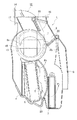
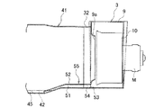
第2実施形態:図5〜図7は第2実施形態の車両用空調装置を示すものである。図5はインテークボックス近傍を示す前面図、図6はインテークボックス取付部近傍を示す側面図、図7はブロアの吸込口近傍を示す図であって分図aは縦断面図、分図bは側面図である。なお、第1実施形態と同様の構成については同一符号を付して説明を省略する。
【0030】
この第2実施形態の車両用空調装置は、インテークボックス41の雨水貯留部42が透孔43と離間し且つ透孔43より低い位置に存在する点が第1実施形態の構成と異なっている。
【0031】
インテークボックス41は、その筒状取付部44が先端側(ブロア側)に向けて先窄まり形状となっており、その底壁部45はブロア3側に向けて上がり傾斜している。そのため、インテークボックス41の雨水貯留部42は、ブロア3から離間している。
【0032】
ブロア3に設けられたインテークボックス41に臨む透孔43は、その周縁からインテークボックス41内に向けてチューブ取付用のボス47が突設されている。このボス47にはチューブ48が取付られており、チューブ48の一端は、インテークボックス41の貯留部42に配置されている。
【0033】
このような第2実施形態の車両用空調装置によれば、インテークボックス31とブロア3との差圧により、透孔43およびボス47およびチューブ48よりなる誘導通路49を通じて、インテークボックス41内に貯留する雨水をブロア3内に吸い込むことができる。これにより第1実施形態と同様の効果を得ることができる。また、このような第2実施形態の車両用空調装置によれば、第1実施形態に比べ、チューブ48を利用するため部品点数が増加するものの、チューブ48を比較的自由に配索することができるため、インテークボックス41およびブロア3の設計自由度が高まる。
【0034】
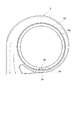
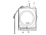
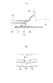
第3実施形態:図8〜図10は第3実施形態の車両用空調装置を示すものである。図8はインテークボックス近傍を示す前面図、図9はインテークボックス取付部近傍を示す側面図、図10はブロアの吸込口近傍を示す図であって分図aは縦断面図、分図bは側面図である。なお、第2実施形態と同様の構成については同一符号を付して説明を省略する。
【0035】
この第3実施形態の車両用空調装置は、前記チューブ48の代わりに、断面コ字状の樹脂製の蓋体52を利用した点で第2実施形態と相違している。
【0036】
この蓋体52は、インテークボックス41の底壁部45に取り付けられてこの底壁部45との間に通路51を形成する。この通路51は、一端が貯留部42に臨んで配置され、他端がブロア3の透孔53周縁からインテークボックス51内に向けて突設される取付部54に連結されている。これにより透孔53および取付部54および通路51によって、インテークボックス41の貯留部42に溜まる雨水をブロア3に誘導する誘導通路55が形成される。
【0037】
このような第3実施形態の車両用空調装置によれば、第1、2実施形態と同様の効果を得られる。
【0038】
以上のように、本発明によれば、インテークボックスの底壁部に貯留する流体をブロアに誘導する誘導通路を設けたため、インテークボックスの底壁部に貯留する雨水は、まずインテークボックスとブロアとの差圧によりブロアに導かれ、さらにブロアによって送風された後、冷却用熱交換器に捕獲されて凝縮水として冷却用熱交換器の下方のドレインパイプから排出される。そのため、インテークボックスにドレインパイプを設ける必要がない。結果、インテークボックスの排水構造を備えつつも、インテークボックスと空調ユニットとの取付作業性が向上し、また、車体への取付作業性が向上する。
【図面の簡単な説明】
【図1】第1実施形態の車両用空調装置を示す一部破断部を含む前面図。
【図2】同車両用空調装置の側断面図。
【図3】同車両用空調装置のブロアの取付部近傍を示す側面図。
【図4】同車両用空調装置のブロアの透孔の近傍を示す図であって、分図aは断面図、分図bは側面図。
【図5】第2実施形態の車両用空調装置の要を示す前面図。
【図6】同車両用空調装置の側面図。
【図7】同車両用空調装置のブロアの透孔の近傍を示す図であって、分図aは断面図、分図bは側面図。
【図8】第3実施形態の車両用空調装置の要を示す前面図。
【図9】同車両用空調装置の側面図。
【図10】同車両用空調装置のブロアの透孔の近傍を示す図であって、分図aは断面図、分図bは側面図。
【符号の説明】
3 ブロア
12 インテークボックス
33 底壁部
34 貯留部
35 透孔(誘導通路)
41 インテークボックス
43 透孔
45 底壁部
48 チューブ
49 誘導通路
55 誘導通路[0001]
BACKGROUND OF THE INVENTION
The present invention relates to a vehicle air conditioner.
[0002]
[Prior art]
A conventional vehicle air conditioner includes an intake box that selectively introduces inside and outside air, a blower that blows air introduced from the intake box downstream, and a temperature control unit that dehumidifies and regulates the air from the blower. (See, for example, Patent Document 1). The temperature control unit includes a cooling unit and a heating unit, and the cooling unit and the heating unit are formed integrally or separately. Further, the intake box, the blower, and the temperature control unit are formed integrally or separately.
[0003]
[Patent Document 1]
JP 2002-79824 A (FIG. 1)
[0004]
[Problems to be solved by the invention]
In this type of vehicle air conditioner, consideration for rainwater entering the intake box is not sufficient, and there is a concern that rainwater may be stored in the intake box and mold may be generated by the stored water.
[0005]
As a measure to solve this, a structure in which a drain pipe is provided in the intake box is also conceivable. However, generally, the cooling unit (temperature control unit) is provided with a drain pipe below the cooling heat exchanger in order to discharge condensed water dehumidified and condensed by the cooling heat exchanger. Therefore, in the structure in which the drain pipe is provided in the intake box, the structure is provided with two drain pipes as an air conditioner, which not only complicates the apparatus but also complicates the assembly work.
[0006]
The present invention has been made against the background of the above-described prior art, and an object of the present invention is to provide a vehicle air conditioner that prevents rainwater from being stored in the intake box without providing a drain pipe in the intake box. Is an offer.
[0007]
[Means for Solving the Problems]
In the first aspect of the invention, the intake box for selectively introducing the inside and outside air, and a blower for blowing the air introduced from the intake box downstream, the air from the blower is dehumidified. In the vehicle air conditioner that regulates and blows out, a guide passage for guiding the fluid stored in the bottom wall portion of the intake box into the blower is provided on the suction port side of the scroll chamber of the blower. .
[0008]
According to a second aspect of the present invention, in the vehicle air conditioner according to the first aspect, a through hole is provided in a partition wall that divides the intake box and the blower, and one end of the intake box has an intake box. The guide passage is formed by connecting a tube disposed in the storage section.
[0009]
According to a third aspect of the present invention, in the vehicle air conditioner according to the first aspect, the intake box and the blower are connected in a substantially horizontal direction, and a partition wall that partitions the intake box and the blower is provided. By providing a through hole in a lower end portion, a bottom wall portion of the intake box is inclined downward toward the through hole, and arranged so that the through hole faces a storage portion of the intake box, the guide passage Is formed.
[0010]
【The invention's effect】
According to the first aspect of the present invention, the stored water stored in the bottom wall portion of the intake box is guided to the blower through the guide passage by the differential pressure between the intake box and the blower. The water guided to the blower is blown in the form of a mist to the downstream temperature control unit by the fan, captured in the heat exchanger for cooling in the temperature control unit, and drained below the heat exchanger for cooling as condensed water. Discharged from the pipe.
[0011]
As described above, according to the first aspect of the present invention, by providing the guide passage, it is possible to drain rainwater that has entered the intake box without providing the drain pipe structure of the intake box.
[0012]
According to the second aspect of the present invention, since the guide passage is constituted by the through hole and the tube connected to the through hole, the invention of the first aspect can be embodied with a relatively simple structure.
[0013]
According to the invention described in
[0014]
DETAILED DESCRIPTION OF THE INVENTION
DESCRIPTION OF EXEMPLARY EMBODIMENTS Hereinafter, preferred embodiments of a vehicle air conditioner according to the invention will be described with reference to the drawings.
[0015]
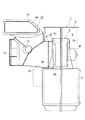
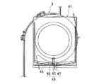
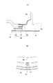
1 to 4 show a vehicle air conditioner according to a first embodiment. FIG. 1 is a front view including a partially broken portion showing the vehicle air conditioner according to the first embodiment. 2 is a side sectional view of the vehicle air conditioner, FIG. 3 is a side view showing the vicinity of the blower of the vehicle air conditioner shown in FIGS. 1 and 2, and FIG. 4 is a view showing the vicinity of the through hole of the blower of the vehicle air conditioner. The fractional diagram a is a sectional view, and the fractional diagram b is a side view.
[0016]
The vehicle air conditioner according to this embodiment includes an
[0017]
Basic structure of the intake box The
[0018]
Basic structure of blower integrated temperature control unit A blower integrated temperature control unit 1 includes a
[0019]
The
[0020]
The
[0021]
The
[0022]
The
[0023]
On the downstream side of the air mix chamber P3, a
[0024]
A
[0025]
The rainwater drainage structure of the intake box In this embodiment, the drainage pipe is not formed in the
[0026]
As shown in FIGS. 1 and 4, the
[0027]
Thus, according to the vehicle air conditioner of this embodiment, rainwater that has entered the
[0028]
Moreover, in this embodiment, the following devices are also made. Specifically, using the fact that a blower passage is present immediately below the
[0029]
2nd Embodiment: FIGS. 5-7 shows the vehicle air conditioner of 2nd Embodiment. 5 is a front view showing the vicinity of the intake box, FIG. 6 is a side view showing the vicinity of the intake box mounting portion, FIG. 7 is a view showing the vicinity of the suction port of the blower, a partial view a is a longitudinal sectional view, and a partial view b is It is a side view. In addition, about the structure similar to 1st Embodiment, the same code | symbol is attached | subjected and description is abbreviate | omitted.
[0030]
The vehicle air conditioner of the second embodiment is different from the configuration of the first embodiment in that the
[0031]
The
[0032]
A through
[0033]
According to the vehicle air conditioner of the second embodiment as described above, the pressure is stored in the
[0034]
3rd Embodiment: FIGS. 8-10 shows the vehicle air conditioner of 3rd Embodiment. FIG. 8 is a front view showing the vicinity of the intake box, FIG. 9 is a side view showing the vicinity of the intake box mounting portion, FIG. 10 is a view showing the vicinity of the suction port of the blower, a partial view a is a longitudinal sectional view, and a partial view b is It is a side view. In addition, about the structure similar to 2nd Embodiment, the same code | symbol is attached | subjected and description is abbreviate | omitted.
[0035]
The vehicle air conditioner according to the third embodiment is different from the second embodiment in that a
[0036]
The
[0037]
According to the vehicle air conditioner of the third embodiment, the same effects as those of the first and second embodiments can be obtained.
[0038]
As described above, according to the present invention, since the guide passage that guides the fluid stored in the bottom wall portion of the intake box to the blower is provided, the rainwater stored in the bottom wall portion of the intake box first includes the intake box and the blower. After being guided to the blower by the pressure difference of the pressure and further blown by the blower, it is captured by the cooling heat exchanger and discharged as condensed water from the drain pipe below the cooling heat exchanger. Therefore, it is not necessary to provide a drain pipe in the intake box. As a result, the mounting workability between the intake box and the air conditioning unit is improved while the drainage structure of the intake box is provided, and the mounting workability to the vehicle body is improved.
[Brief description of the drawings]
FIG. 1 is a front view including a partially broken portion showing a vehicle air conditioner according to a first embodiment.
FIG. 2 is a side sectional view of the vehicle air conditioner.
FIG. 3 is a side view showing the vicinity of a blower mounting portion of the vehicle air conditioner.
FIG. 4 is a view showing the vicinity of a through hole of a blower of the vehicle air conditioner, where a part a is a sectional view and a part b is a side view.
FIG. 5 is a front view showing an essential part of a vehicle air conditioner according to a second embodiment.
FIG. 6 is a side view of the vehicle air conditioner.
FIG. 7 is a view showing the vicinity of a through hole of a blower of the vehicle air conditioner, wherein a partial view a is a cross-sectional view and a partial view b is a side view.
FIG. 8 is a front view showing an essential part of a vehicle air conditioner according to a third embodiment.
FIG. 9 is a side view of the vehicle air conditioner.
FIG. 10 is a view showing the vicinity of a through hole of a blower of the vehicle air conditioner, where a part a is a sectional view and a part b is a side view.
[Explanation of symbols]
3
41
Claims (3)
前記インテークボックス(12、41)の底壁部(33、45)に貯留する流体をブロア(3)内に誘導する誘導通路(35、49、55)を、ブロア(3)のスクロール室(9)の吸込口(9a)側に設けたことを特徴とする車両用空調装置。An intake box (12, 41) that selectively introduces internal and external air, and a blower (3) that blows air introduced from the intake box (12, 41) downstream from the blower (3). In the vehicle air conditioner that dehumidifies the temperature of the air and blows it out,
The guide passages (35, 49, 55) for guiding the fluid stored in the bottom walls (33, 45) of the intake box (12, 41) into the blower (3) are connected to the scroll chamber (9) of the blower (3). ) On the suction port (9a) side of the vehicle air conditioner.
前記ブロア(3)に透孔(43)を設け、該透孔(43)に、一端がインテークボックス(41)の貯留部(34)に配されたチューブ(48)を接続することで、前記誘導通路(49)を形成したことを特徴とする車両用空調装置。The vehicle air conditioner according to claim 1,
By providing a through hole (43) in the blower (3), and connecting a tube (48), one end of which is arranged in the storage part (34) of the intake box (41), to the through hole (43), A vehicle air conditioner characterized in that a guide passage (49) is formed.
前記インテークボックス(12)と前記ブロア(3)とを略水平方向に連設し、
前記インテークボックス(12)の底壁部(33)をブロア(3)側に向けて下り傾斜させて構成することでインテークボックス(12)の貯留部(34)をブロア(3)に近接配置し、該ブロア(3)の前記貯留部(34)に臨む位置に透孔(35)を設けることで、前記誘導通路(35)を形成したことを特徴とする車両用空調装置。The vehicle air conditioner according to claim 1,
The intake box (12) and the blower (3) are connected in a substantially horizontal direction,
By arranging the bottom wall portion (33) of the intake box (12) to be inclined downward toward the blower (3), the storage portion (34) of the intake box (12) is disposed close to the blower (3). The vehicle air conditioner is characterized in that the guide passage (35) is formed by providing a through hole (35) at a position facing the storage part (34) of the blower (3).
Priority Applications (1)
| Application Number | Priority Date | Filing Date | Title |
|---|---|---|---|
| JP2002261365A JP4008317B2 (en) | 2002-09-06 | 2002-09-06 | Air conditioner for vehicles |
Applications Claiming Priority (1)
| Application Number | Priority Date | Filing Date | Title |
|---|---|---|---|
| JP2002261365A JP4008317B2 (en) | 2002-09-06 | 2002-09-06 | Air conditioner for vehicles |
Publications (2)
| Publication Number | Publication Date |
|---|---|
| JP2004098782A JP2004098782A (en) | 2004-04-02 |
| JP4008317B2 true JP4008317B2 (en) | 2007-11-14 |
Family
ID=32261762
Family Applications (1)
| Application Number | Title | Priority Date | Filing Date |
|---|---|---|---|
| JP2002261365A Expired - Fee Related JP4008317B2 (en) | 2002-09-06 | 2002-09-06 | Air conditioner for vehicles |
Country Status (1)
| Country | Link |
|---|---|
| JP (1) | JP4008317B2 (en) |
Families Citing this family (5)
| Publication number | Priority date | Publication date | Assignee | Title |
|---|---|---|---|---|
| JP5000955B2 (en) * | 2006-09-08 | 2012-08-15 | カルソニックカンセイ株式会社 | Drainage structure of vehicle air conditioner |
| JP4464422B2 (en) | 2007-06-06 | 2010-05-19 | カルソニックカンセイ株式会社 | Drainage structure of vehicle air conditioner |
| DE102010062406B4 (en) * | 2010-12-03 | 2023-08-10 | Halla Visteon Climate Control Corporation | Air conditioner for a vehicle |
| JP6706597B2 (en) * | 2017-06-20 | 2020-06-10 | 株式会社ヴァレオジャパン | Blower for vehicle |
| CN115626032A (en) * | 2022-10-31 | 2023-01-20 | 重庆长安汽车股份有限公司 | Air inlet box shell with double-drainage structure, heating ventilation air-conditioning assembly and vehicle |
-
2002
- 2002-09-06 JP JP2002261365A patent/JP4008317B2/en not_active Expired - Fee Related
Also Published As
| Publication number | Publication date |
|---|---|
| JP2004098782A (en) | 2004-04-02 |
Similar Documents
| Publication | Publication Date | Title |
|---|---|---|
| US5673747A (en) | Rear air-conditioning unit for use in vehicle | |
| US7284388B2 (en) | Air conditioner | |
| JP2004218446A (en) | Centrifugal blower | |
| JP2001277837A (en) | Air conditioning unit for automobile | |
| JP4082121B2 (en) | Air conditioner for vehicles | |
| CN110520315A (en) | Car air-conditioner | |
| CN108698479B (en) | Air conditioner for vehicle | |
| EP2000338A1 (en) | Water discharge structure of vehicle air-conditioning system | |
| JP2010100140A (en) | Vehicular air-conditioner | |
| JP4008317B2 (en) | Air conditioner for vehicles | |
| JP3832307B2 (en) | Air conditioner for vehicles | |
| KR100590330B1 (en) | Combined air conditioner | |
| JP4682443B2 (en) | Air conditioner for vehicles | |
| JP2014061790A (en) | Air conditioner for vehicle | |
| JP2000094946A (en) | Vehicle air conditioner | |
| CN101802516A (en) | Condensate Management | |
| JP2002331823A (en) | Condensed water discharge device of cooler unit | |
| KR101971946B1 (en) | Air conditioner for vehicle | |
| JP2011157002A (en) | Drain structure of air conditioner for vehicle | |
| JP3934257B2 (en) | Air conditioner for automobile | |
| JP5092826B2 (en) | Air conditioner | |
| JP3111894B2 (en) | Vehicle air conditioner | |
| JP5527302B2 (en) | Blower | |
| KR100917579B1 (en) | Drainage Structure of HVAC | |
| JP4070501B2 (en) | Unit structure of vehicle air conditioner |
Legal Events
| Date | Code | Title | Description |
|---|---|---|---|
| A621 | Written request for application examination |
Free format text: JAPANESE INTERMEDIATE CODE: A621 Effective date: 20041202 |
|
| A131 | Notification of reasons for refusal |
Free format text: JAPANESE INTERMEDIATE CODE: A131 Effective date: 20070605 |
|
| A521 | Written amendment |
Free format text: JAPANESE INTERMEDIATE CODE: A523 Effective date: 20070723 |
|
| TRDD | Decision of grant or rejection written | ||
| A01 | Written decision to grant a patent or to grant a registration (utility model) |
Free format text: JAPANESE INTERMEDIATE CODE: A01 Effective date: 20070821 |
|
| A61 | First payment of annual fees (during grant procedure) |
Free format text: JAPANESE INTERMEDIATE CODE: A61 Effective date: 20070829 |
|
| FPAY | Renewal fee payment (event date is renewal date of database) |
Free format text: PAYMENT UNTIL: 20100907 Year of fee payment: 3 |
|
| R150 | Certificate of patent or registration of utility model |
Free format text: JAPANESE INTERMEDIATE CODE: R150 |
|
| S531 | Written request for registration of change of domicile |
Free format text: JAPANESE INTERMEDIATE CODE: R313531 |
|
| FPAY | Renewal fee payment (event date is renewal date of database) |
Free format text: PAYMENT UNTIL: 20100907 Year of fee payment: 3 |
|
| R350 | Written notification of registration of transfer |
Free format text: JAPANESE INTERMEDIATE CODE: R350 |
|
| FPAY | Renewal fee payment (event date is renewal date of database) |
Free format text: PAYMENT UNTIL: 20110907 Year of fee payment: 4 |
|
| FPAY | Renewal fee payment (event date is renewal date of database) |
Free format text: PAYMENT UNTIL: 20130907 Year of fee payment: 6 |
|
| R250 | Receipt of annual fees |
Free format text: JAPANESE INTERMEDIATE CODE: R250 |
|
| LAPS | Cancellation because of no payment of annual fees |