EP1908613A1 - Unité soufflante, notamment pour véhicule - Google Patents
Unité soufflante, notamment pour véhicule Download PDFInfo
- Publication number
- EP1908613A1 EP1908613A1 EP06291558A EP06291558A EP1908613A1 EP 1908613 A1 EP1908613 A1 EP 1908613A1 EP 06291558 A EP06291558 A EP 06291558A EP 06291558 A EP06291558 A EP 06291558A EP 1908613 A1 EP1908613 A1 EP 1908613A1
- Authority
- EP
- European Patent Office
- Prior art keywords
- blower unit
- flow
- housing
- double
- cross
- Prior art date
- Legal status (The legal status is an assumption and is not a legal conclusion. Google has not performed a legal analysis and makes no representation as to the accuracy of the status listed.)
- Granted
Links
Images
Classifications
-
- B—PERFORMING OPERATIONS; TRANSPORTING
- B60—VEHICLES IN GENERAL
- B60H—ARRANGEMENTS OF HEATING, COOLING, VENTILATING OR OTHER AIR-TREATING DEVICES SPECIALLY ADAPTED FOR PASSENGER OR GOODS SPACES OF VEHICLES
- B60H1/00—Heating, cooling or ventilating devices
- B60H1/00457—Ventilation unit, e.g. combined with a radiator
- B60H1/00471—The ventilator being of the radial type, i.e. with radial expulsion of the air
-
- B—PERFORMING OPERATIONS; TRANSPORTING
- B60—VEHICLES IN GENERAL
- B60H—ARRANGEMENTS OF HEATING, COOLING, VENTILATING OR OTHER AIR-TREATING DEVICES SPECIALLY ADAPTED FOR PASSENGER OR GOODS SPACES OF VEHICLES
- B60H1/00—Heating, cooling or ventilating devices
- B60H1/00507—Details, e.g. mounting arrangements, desaeration devices
- B60H2001/00628—Adaption for left or right hand drive
Definitions
- the invention relates to a blower unit, in particular for a motor vehicle, according to the preamble of claim 1.
- blower unit which can be used for left and right-hand drive vehicles.
- the blower unit has a housing with a top wall, a bottom wall and two opposing walls, which together define two open and opposite end faces with the same profile.
- the housing also has a mounting frame with a fan built into the frame.
- an impeller, an impeller blower motor, and two symmetrical half shells are provided, which are assembled to form a volute casing in which the impeller and the motor are arranged.
- such a blower unit is usually suitable only for one vehicle type.
- a blower unit in particular for a motor vehicle, with a double-flow impeller, wherein a part of the housing or a cover closes the opening of the intake duct of a flood in a stable manner.
- the cover may be formed directly by the housing, which in this case must have a special design. However, it can also be formed, for example, as a lid, fixed in place of the intake duct on the housing, for example by means of clipping or with screws.
- blower unit can be used in particular for smaller motor vehicles, while the large, designed with two intake ducts and double-flow blower unit can be used, for example, for vans.
- double-flow blower unit By apart from the lack of intake substantially the same design of the blower units many common parts can be used, whereby the numbers increased and thereby the manufacturing cost can be reduced.
- single-flow blower unit it is also easy to change over from left to right-hand drive under the appropriate installation conditions.
- the blow-out duct preferably corresponds to the blow-out duct of a double-flow blower unit, ie in the area of a subsequent heating and / or air conditioning unit, no changes between individual variants are required given a suitable design of the blower unit and sufficient installation space.
- the cross-section of the intake duct in a single-flow blower unit is preferably larger than the cross-section of an intake duct in a double-use blower unit, but it may also be unchanged, so that more equal parts are possible.
- the cross section of the single-flow fan unit is preferably at most twice as large as the cross-section of an intake duct in a double-use fan unit, in particular 1.2 to 1.7 times, more preferably 1.5 times large.
- the blower unit preferably has a multi-part housing formed on plastic.
- Such housing can be produced inexpensively and allow a relatively simple installation and removal of the impeller and / or motor.
- the housing is separable in the median plane.
- such a blower unit is installed in its twin-used form in a van or other, larger motor vehicle and in its single-flow used form in a smaller motor vehicle. It can be part of a heating or air conditioning system.
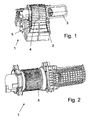
- blower unit 1 'of a motor vehicle air conditioner with following the blower unit 1' arranged evaporator and heater and a plurality of the tempered air the vehicle interior supplying air ducts used in a van is described below first becomes.
- the structure of the air conditioner per se corresponds to that of a conventional air conditioner and will therefore not be described in detail below.
- the blower unit 1 has a multi-part housing 2 made of plastic with two intake ports 3 and 3', a two-part scroll member 4 and a blow-out 5, a arranged on a shaft, double-flow impeller 6 made of plastic and a drive motor.
- the intake ducts 3 are arranged on the right and left of the impeller 6, so that air is sucked in from both sides by means of the rotating double-flow impeller 6 and pushed into the exhaust duct 5.
- the structure of the fan unit 1 ' is substantially mirror-inverted to the median plane, which runs between the two floods.
- the structure of the blower unit 1 ' substantially corresponds to that of a conventional double-flow blower unit.
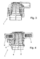
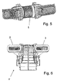
- FIGS. 1 to 3 show a blower unit 1 according to the exemplary embodiment. If not mentioned below, this blower unit 1 corresponds to the previously described blower unit 1 '.
- one intake channel 3 is arranged on one side, in the present case in the motor vehicle on the right.
- the intake passage 3 is formed with a slightly larger cross-section, but this need not necessarily be the case. Rather, the same components for the corresponding intake as for the previously described blower unit 1 can be used.
- a cover in the form of a plastic cap is provided in place of the left intake duct 3 ', which is mounted airtight on the housing 2, so that no air from the vehicle interior can be sucked from the left and sucked from the right air essentially distributed over the entire double-flow impeller 6, ie In the absence of the second intake duct 3 ', the actually double-flow blower is in principle operated in single-flow.
Landscapes
- Physics & Mathematics (AREA)
- Thermal Sciences (AREA)
- Engineering & Computer Science (AREA)
- Mechanical Engineering (AREA)
- Structures Of Non-Positive Displacement Pumps (AREA)
- Air-Conditioning For Vehicles (AREA)
Priority Applications (2)
| Application Number | Priority Date | Filing Date | Title |
|---|---|---|---|
| DE200650004679 DE502006004679D1 (de) | 2006-10-05 | 2006-10-05 | Gebläseeinheit, insbesondere für ein Kraftfahrzeug |
| EP20060291558 EP1908613B1 (fr) | 2006-10-05 | 2006-10-05 | Unité soufflante, notamment pour véhicule |
Applications Claiming Priority (1)
| Application Number | Priority Date | Filing Date | Title |
|---|---|---|---|
| EP20060291558 EP1908613B1 (fr) | 2006-10-05 | 2006-10-05 | Unité soufflante, notamment pour véhicule |
Publications (2)
| Publication Number | Publication Date |
|---|---|
| EP1908613A1 true EP1908613A1 (fr) | 2008-04-09 |
| EP1908613B1 EP1908613B1 (fr) | 2009-08-26 |
Family
ID=37831481
Family Applications (1)
| Application Number | Title | Priority Date | Filing Date |
|---|---|---|---|
| EP20060291558 Ceased EP1908613B1 (fr) | 2006-10-05 | 2006-10-05 | Unité soufflante, notamment pour véhicule |
Country Status (2)
| Country | Link |
|---|---|
| EP (1) | EP1908613B1 (fr) |
| DE (1) | DE502006004679D1 (fr) |
Citations (4)
| Publication number | Priority date | Publication date | Assignee | Title |
|---|---|---|---|---|
| US1978459A (en) * | 1932-05-31 | 1934-10-30 | American Air Filter Co | Fan or blower housing |
| FR2529515A1 (fr) * | 1982-07-01 | 1984-01-06 | Sueddeutsche Kuehler Behr | Equipement de climatisation pour vehicule automobile |
| DE19908501A1 (de) * | 1999-02-26 | 2000-03-30 | Daimler Chrysler Ag | Radialgebläse |
| EP1614564A2 (fr) * | 2004-07-09 | 2006-01-11 | Sanden Corporation | Ventilateur centrifuge |
-
2006
- 2006-10-05 DE DE200650004679 patent/DE502006004679D1/de active Active
- 2006-10-05 EP EP20060291558 patent/EP1908613B1/fr not_active Ceased
Patent Citations (4)
| Publication number | Priority date | Publication date | Assignee | Title |
|---|---|---|---|---|
| US1978459A (en) * | 1932-05-31 | 1934-10-30 | American Air Filter Co | Fan or blower housing |
| FR2529515A1 (fr) * | 1982-07-01 | 1984-01-06 | Sueddeutsche Kuehler Behr | Equipement de climatisation pour vehicule automobile |
| DE19908501A1 (de) * | 1999-02-26 | 2000-03-30 | Daimler Chrysler Ag | Radialgebläse |
| EP1614564A2 (fr) * | 2004-07-09 | 2006-01-11 | Sanden Corporation | Ventilateur centrifuge |
Also Published As
| Publication number | Publication date |
|---|---|
| EP1908613B1 (fr) | 2009-08-26 |
| DE502006004679D1 (de) | 2009-10-08 |
Similar Documents
| Publication | Publication Date | Title |
|---|---|---|
| DE102011051489B4 (de) | Gebläse-Luftansaugungsvorrichtung | |
| DE3006318C2 (de) | Lüftungsvorrichtung | |
| WO2017167584A1 (fr) | Pompe à vide avec insonorisation | |
| EP1867375A1 (fr) | Ventilateur à filtre comprenant un dispositif de fixation rapide | |
| EP1902220B1 (fr) | Turbine | |
| DE2939385C2 (de) | Radialgebläse, insbesondere für Heiz- oder Klimaanlagen von Fahrzeugen | |
| DE102018211809A1 (de) | Gehäuse für einen Ventilator und Ventilator | |
| WO2018007318A1 (fr) | Appareil de cuisson industriel | |
| EP2275687A2 (fr) | Boîtier de ventilateur radial | |
| EP2333348A2 (fr) | Boîtier de ventilateur radial | |
| EP2290298A2 (fr) | Dispositif de déviation d'un flux d'air notamment pour une hotte d'aspiration | |
| DE102020200363A1 (de) | Tragmodul für einen Ventilator und Ventilator mit einem entsprechenden Tragmodul | |
| EP2702333B1 (fr) | Methode de regulation d'une installation de ventilation comprenant une chambre de mixage | |
| DE602006000387T2 (de) | Doppelgebläseanordnung für Kraftfahrzeuge | |
| WO2000058629A1 (fr) | Compresseur a conduit lateral | |
| DE60306733T2 (de) | Radiallüfter | |
| EP1908613B1 (fr) | Unité soufflante, notamment pour véhicule | |
| DE3222164C2 (fr) | ||
| DE1924611A1 (de) | Geblaese | |
| DE102005016820B4 (de) | Großmotor | |
| EP1128069A2 (fr) | Pompe à effet visqueux | |
| DE102008010182A1 (de) | Gehäuse für eine Gasfördereinrichtung | |
| EP2080910B1 (fr) | Ventilateur, notamment pour la ventilation de véhicules | |
| DE3905092C2 (fr) | ||
| EP1741933B1 (fr) | Roue à aubes et procédé pour sa fabrication |
Legal Events
| Date | Code | Title | Description |
|---|---|---|---|
| PUAI | Public reference made under article 153(3) epc to a published international application that has entered the european phase |
Free format text: ORIGINAL CODE: 0009012 |
|
| AK | Designated contracting states |
Kind code of ref document: A1 Designated state(s): AT BE BG CH CY CZ DE DK EE ES FI FR GB GR HU IE IS IT LI LT LU LV MC NL PL PT RO SE SI SK TR |
|
| AX | Request for extension of the european patent |
Extension state: AL BA HR MK RS |
|
| 17P | Request for examination filed |
Effective date: 20081009 |
|
| 17Q | First examination report despatched |
Effective date: 20081106 |
|
| AKX | Designation fees paid |
Designated state(s): DE FR GB |
|
| GRAP | Despatch of communication of intention to grant a patent |
Free format text: ORIGINAL CODE: EPIDOSNIGR1 |
|
| GRAS | Grant fee paid |
Free format text: ORIGINAL CODE: EPIDOSNIGR3 |
|
| GRAA | (expected) grant |
Free format text: ORIGINAL CODE: 0009210 |
|
| AK | Designated contracting states |
Kind code of ref document: B1 Designated state(s): DE FR GB |
|
| REG | Reference to a national code |
Ref country code: GB Ref legal event code: FG4D Free format text: NOT ENGLISH |
|
| REF | Corresponds to: |
Ref document number: 502006004679 Country of ref document: DE Date of ref document: 20091008 Kind code of ref document: P |
|
| PLBE | No opposition filed within time limit |
Free format text: ORIGINAL CODE: 0009261 |
|
| STAA | Information on the status of an ep patent application or granted ep patent |
Free format text: STATUS: NO OPPOSITION FILED WITHIN TIME LIMIT |
|
| 26N | No opposition filed |
Effective date: 20100527 |
|
| PGFP | Annual fee paid to national office [announced via postgrant information from national office to epo] |
Ref country code: GB Payment date: 20101025 Year of fee payment: 5 |
|
| GBPC | Gb: european patent ceased through non-payment of renewal fee |
Effective date: 20121005 |
|
| PG25 | Lapsed in a contracting state [announced via postgrant information from national office to epo] |
Ref country code: GB Free format text: LAPSE BECAUSE OF NON-PAYMENT OF DUE FEES Effective date: 20121005 |
|
| REG | Reference to a national code |
Ref country code: DE Ref legal event code: R082 Ref document number: 502006004679 Country of ref document: DE Representative=s name: GRAUEL, ANDREAS, DIPL.-PHYS. DR. RER. NAT., DE Ref country code: DE Ref legal event code: R081 Ref document number: 502006004679 Country of ref document: DE Owner name: MAHLE INTERNATIONAL GMBH, DE Free format text: FORMER OWNER: BEHR FRANCE ROUFFACH S.A.S., ROUFFACH, FR |
|
| REG | Reference to a national code |
Ref country code: FR Ref legal event code: PLFP Year of fee payment: 10 |
|
| REG | Reference to a national code |
Ref country code: FR Ref legal event code: PLFP Year of fee payment: 11 |
|
| REG | Reference to a national code |
Ref country code: FR Ref legal event code: PLFP Year of fee payment: 12 |
|
| REG | Reference to a national code |
Ref country code: FR Ref legal event code: PLFP Year of fee payment: 13 |
|
| PGFP | Annual fee paid to national office [announced via postgrant information from national office to epo] |
Ref country code: DE Payment date: 20181030 Year of fee payment: 13 |
|
| REG | Reference to a national code |
Ref country code: DE Ref legal event code: R119 Ref document number: 502006004679 Country of ref document: DE |
|
| PG25 | Lapsed in a contracting state [announced via postgrant information from national office to epo] |
Ref country code: DE Free format text: LAPSE BECAUSE OF NON-PAYMENT OF DUE FEES Effective date: 20200501 |
|
| PGFP | Annual fee paid to national office [announced via postgrant information from national office to epo] |
Ref country code: FR Payment date: 20201023 Year of fee payment: 15 |
|
| PG25 | Lapsed in a contracting state [announced via postgrant information from national office to epo] |
Ref country code: FR Free format text: LAPSE BECAUSE OF NON-PAYMENT OF DUE FEES Effective date: 20211031 |