EP2000337A2 - Agencement de ventilateur destiné à l'aération d'un véhicule - Google Patents
Agencement de ventilateur destiné à l'aération d'un véhicule Download PDFInfo
- Publication number
- EP2000337A2 EP2000337A2 EP08009045A EP08009045A EP2000337A2 EP 2000337 A2 EP2000337 A2 EP 2000337A2 EP 08009045 A EP08009045 A EP 08009045A EP 08009045 A EP08009045 A EP 08009045A EP 2000337 A2 EP2000337 A2 EP 2000337A2
- Authority
- EP
- European Patent Office
- Prior art keywords
- blower
- arrangement according
- fan
- air
- motor
- Prior art date
- Legal status (The legal status is an assumption and is not a legal conclusion. Google has not performed a legal analysis and makes no representation as to the accuracy of the status listed.)
- Granted
Links
Images


Classifications
-
- B—PERFORMING OPERATIONS; TRANSPORTING
- B60—VEHICLES IN GENERAL
- B60H—ARRANGEMENTS OF HEATING, COOLING, VENTILATING OR OTHER AIR-TREATING DEVICES SPECIALLY ADAPTED FOR PASSENGER OR GOODS SPACES OF VEHICLES
- B60H1/00—Heating, cooling or ventilating devices
- B60H1/00007—Combined heating, ventilating, or cooling devices
- B60H1/00021—Air flow details of HVAC devices
- B60H1/00028—Constructional lay-out of the devices in the vehicle
-
- B—PERFORMING OPERATIONS; TRANSPORTING
- B60—VEHICLES IN GENERAL
- B60H—ARRANGEMENTS OF HEATING, COOLING, VENTILATING OR OTHER AIR-TREATING DEVICES SPECIALLY ADAPTED FOR PASSENGER OR GOODS SPACES OF VEHICLES
- B60H1/00—Heating, cooling or ventilating devices
- B60H1/00457—Ventilation unit, e.g. combined with a radiator
-
- B—PERFORMING OPERATIONS; TRANSPORTING
- B60—VEHICLES IN GENERAL
- B60H—ARRANGEMENTS OF HEATING, COOLING, VENTILATING OR OTHER AIR-TREATING DEVICES SPECIALLY ADAPTED FOR PASSENGER OR GOODS SPACES OF VEHICLES
- B60H1/00—Heating, cooling or ventilating devices
- B60H1/00007—Combined heating, ventilating, or cooling devices
- B60H1/00021—Air flow details of HVAC devices
- B60H2001/00078—Assembling, manufacturing or layout details
- B60H2001/00085—Assembling, manufacturing or layout details of air intake
Definitions
- the invention relates to a blower arrangement, which is arranged in the air conditioning system of a motor vehicle.
- Air conditioning systems for motor vehicles provide a supply of climatically treated air in the interior of the motor vehicle, where it usually exits the air conditioner in the area of the dashboard. Individual outlets are arranged in particular in the foot region, in the middle region and near the inside of the windshield. Air conditioning systems are usually operated in fresh air mode, with air from the environment (usually in the area below the windshield) sucked, conditioned climatic and then fed to the interior. An air conditioner can be operated in the recirculation mode, ie it is no air supplied from the outside, but sucked in the interior, treated and fed back into the interior.
- an additional air conditioning unit is often used, which is usually arranged in the rear area of the center console, and in particular the conditioned air supplies air to the rear area.
- the conditioned air supplies air to the rear area.
- a blower arrangement for ventilation of a vehicle is known in which a blower unit can deliver two separate air streams in a respective blow-out via a double blower.
- the operation of the fan assembly is limited to the recirculation mode.
- the comfort of additional air conditioning units can be increased if they are supplied with fresh air and thus can additionally be operated in fresh air mode.
- the additional air conditioner can be supplied with already preconditioned air from the front air conditioner.
- the invention has for its object to provide an improved fan assembly for ventilation of a motor vehicle available, which has a good utilization of space, increased comfort for the occupants and improved acoustic properties during operation.
- a blower arrangement according to the invention in particular for ventilating a motor vehicle, has a blower driven by a blower motor with at least one, preferably at least two blower wheels. Furthermore, the blower arrangement according to the invention has on the input side at least one intake duct which is provided with a suction opening, and on the output side at least one, preferably two blow-out ducts. This at least one intake duct has an opening cross-section substantially separated from this intake opening for receiving circulating air, and it is further provided that its opening cross-section can be changed by means of a control element.
- This design of the at least one intake channel advantageously makes it possible to extend the operation of the fan assembly by the fresh air mode, which makes it possible that in particular the passengers in the rear of the vehicle are supplied with fresh air. This represents a significant gain in comfort for the occupants.
- control element is preferably a flap.
- control element preferably bands with differently shaped recesses, wherein the bands can be moved in the longitudinal direction and cooperate with an element such that different opening cross-sections are released or closed.
- flap geometries can be used.
- a recirculation flap is preferably mounted about a pivot axis.
- the recirculation damper is preferably mounted in the blower housing, in a further embodiment of the blower arrangement may also preferably be mounted outside the blower housing.
- the position of the recirculating air flap is preferably continuously variable, but in a further embodiment may preferably be discontinuously changeable with the aid of a modified kinematic design for the actuation thereof.
- the blow-off channels preferably discharge the air streams emerging from them, preferably separate from one another, essentially in the horizontal direction.
- At least one circulating-air flap is preferably actuated by at least one lever mechanism.
- a plurality of recirculating air flaps are preferably preferably actuatable separately, preferably each with its own lever mechanism, so that the flexibility of the blower arrangement in the fresh air mode can still be increased. This allows the individual intake ports to be set in an individual operating mode as desired.
- the opening cross section for receiving circulating air of an intake duct is preferably arranged substantially on an underside of the blower housing, so that the circulating air is received substantially from below, for example between a vehicle center tunnel and the blower housing.
- the blow-out channels are preferably formed separately from one another, and in a preferred embodiment of the blower arrangement according to the invention, they deliver the air streams which are separated from the blower arrangement, preferably in a substantially horizontal direction.
- the separation of the blow-off channels advantageously makes it possible to dispense air streams of different temperature from the blower arrangement into the rear region of the vehicle. This increases the comfort for the occupants.
- the fan housing are preferably at least formed two suction chambers, which are preferably preferably separated from each other by a partition. This makes it possible to separate the air streams taken in by the front air conditioner through the intake ducts as far as the blow-off ducts and also inside the blower housing.
- the blower housing is preferably a plastic housing.
- the blower motor is preferably executed encapsulated, whereby the required pressure situation for suction of the air streams is achieved in the blower housing.
- a single fan motor for driving the double fan wherein the fan motor is preferably an electric motor. This advantageously leads to a reduction of the engine noise and thus increases the comfort for the occupants of the vehicle.
- a separate blower motor which has at least one impeller, be formed.
- the individual blowers of the double blower are preferably designed to be single-flow and / or multi-flow.
- flooding refers to the number of suction paths.
- the impeller hubs of a single-flow or multi-flow blower of the double fan are preferably provided with openings.
- the impellers of the double blower are preferably rotationally connected to an output shaft of the blower motor.
- a blower control device is preferably provided for controlling and / or regulating the rotational speed of the blower, which is preferably arranged inside the blower housing.
- a part of the air mass flow is preferably conducted into the blower motor encapsulation for cooling the blower motor and / or the control unit.
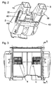
- Fig. 1 1 shows an embodiment of a blower arrangement 1 according to the invention. It essentially comprises a blower housing 2 in which a double blower 4 formed by two blowers is arranged. On the output side, the blower arrangement has two blower channels 7, 8 separated from one another.
- the double fan 4 is driven by means of an electric motor 5, wherein both fans are driven by the common electric motor 5.
- the double fan 4 is connected on the input side with two separate intake channels 9, 10.
- the respective intake channel 9, 10 serves to feed one of the two fans with an associated intake stream.
- the double fan 4 is connected on the output side to the exhaust channels 7, 8.
- Fig. 2 shows a perspective view from below of an embodiment of the blower arrangement according to the invention, in which on the underside of the blower housing 2 on each side in the region of the intake ports 9, 10 each a recirculating air flap 40 is arranged.
- the recirculation flaps 40 are each actuated by an associated lever mechanism 35, 36.
- Fig. 3 shows a front view of an embodiment according to an embodiment of the present invention.
- the two blowers of the double blower 4 are driven by a common blower motor 5.
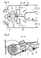
- Fig. 4 shows a sectional view from the side of an embodiment of the blower arrangement according to the invention along the section line AA.
- the recirculating air flaps 40 are arranged and each pivotably mounted about their pivot axis 48, which is arranged substantially at one end of the circulating air cap 40.
- the recirculation flaps 40 are in a position in which the opening cross-section of the recirculation inlet is closed.
- a blower control device 17 is arranged, which in particular controls the speed of the blower motor, but can also take on further tasks for the operation of the blower arrangement.
- the direction and course of the airflow from the front air conditioner (airflow F) to an intake duct to the blower is indicated by arrows.
- the direction of this air flow is slightly inclined in this embodiment of the invention blower arrangement relative to the horizontal.
- Fig. 5 is a section through an embodiment of the blower arrangement according to the invention along the section line BB according to Fig. 4 represents.
- blower housing 2 blower motor 5 and each impeller 3 of a blower, a plurality of annular gaps 21 is formed, which each serve between the impeller 3 and blower motor 5 for the suction of the inner floods.
- a partition wall 20 is formed, which in this area of the suction chambers 24, 25 keep the incoming air streams from the intake ports 9, 10 and possibly the opening cross sections of the outside air inlet separated. This can be in the rear area, z. B.
- the left and right side of the footwell in the rear or in the area of the B-pillar separately air-conditioned separately air-conditioned.
- the direction of the incoming and outgoing air flows is again shown schematically with the help of arrows.
- the air streams at the inlets and the outlets are substantially parallel to each other.
- Fig. 6 is a section of an embodiment of the blower according to the invention according to Fig. 4 shown, wherein the recirculating air flap 40 has been pivoted about the pivot axis 48 such that the recirculating air flap 40 is now in the position for the partial recirculation mode of the fan assembly.
- the fan assembly is supplied with airflow F from the front air conditioner (not shown).
- the recirculating air flap 40 a gap between the recirculating air flap 40 and the inside of the intake passage is formed, so that still a proportion of preconditioned air from the front air conditioner after passing the recirculation flap 40 in the main flow direction can flow to the blower.
- air flow U The largest amount of air (air flow U) is absorbed by the opening cross-section on the underside of the intake duct and fed to the double fan 4.
- the recirculating air flap 40 completely block the supply of preconditioned fresh air (airflow F) from the front air conditioner in the main flow direction to the fan, so that an air flow is absorbed substantially only by the opening cross section on the underside of the intake duct.
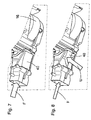
- Fig. 7 shows a perspective view from below of an embodiment of the blower device according to the invention for the mode, in the preconditioned air from the front air conditioner (air flow F) is supplied.
- air flow F air flow
- the wheels 3 of the double fan 4 are each received in a spiral 16, so that the double fan 4 is completely closed from the environment.
- the recirculation flap 40 prevents in this position, that air in the region of the opening cross-section of the recirculation inlet on the underside of the fan housing 2 can occur.
- Fig. 8 shows a perspective view seen from below an embodiment according to Fig. 7 the blower arrangement for the partial recirculation mode in which the recirculation flap 40 with respect to the position of Fig. 7 was pivoted so that in addition to the air flow from the front air conditioner (air flow F) and an air flow through the opening cross section in the region of the recirculation air inlet (air flow U) can occur.
- air flow F front air conditioner
- air flow U air flow
- Fig. 9 shows a recirculating air flap 40 according to the invention for the recirculation air intake on the left side of the fan assembly, which increases or decreases the opening cross section of the recirculation air intake depending on their position.
- the recirculation flap 40 is designed as a one-piece component.
- the recirculating air flap 40 has at one end a substantially cylindrical holder 46, in the interior of which a receptacle 41 is formed.
- the receptacle 41 is formed by a recess which extends along the longitudinal axis of the holder 46 and has a substantially square cross-section.
- a plurality of stiffening ribs 44 are formed, which extend essentially to the other end region of the recirculating-air flap 40 in its longitudinal direction.
- the height of the stiffening ribs 44 is maximum in the area of the receptacle 46 and decreases up to the receptacle 46 on the opposite side of the recirculating-air flap 40.
- Each stiffening rib 44 has an upper edge, the shape of which is bent.
- At a transverse end of the recirculating air flap 40 is of this Traverse transverse in the transverse direction of the recirculation flap 40 to the interior spaced apart a flap fin 42 formed whose design is substantially triangular-shaped.
- the flap fin 42 is bounded toward the interior of the recirculation flap 40 by a fin inner wall 45, which extends from one end of the recirculation flap 40 substantially to the region of the holder 46.
- a fin bar 43rd On the upper side of the flap fin 42 extends in the transverse direction of the fin inner wall 45 to a transverse end of the recirculating air flap 40.
- Fig. 10 shows a perspective view of the recirculating air flap 40 according to Fig. 9 , On the fins inner wall 45 opposite side of the fin 42, the substantially triangular-shaped fin outer wall 47 extends.
- Fig. 11 an embodiment of the blower arrangement 1 according to the invention is shown:
- the blower arrangement is connected to an additional air conditioner 100, which has at least one evaporator 101 and at least one radiator 102 for the air conditioning of the exiting air streams from the blower assembly 1.
- the auxiliary air conditioner 100 has at one end a plurality of air outlet channels, which include channels for the rear ventilation 105, for the ventilation of the footwell in the rear 103 and for the ventilation of the area of the B-pillar 104.
- the mounting position of this module is as in Fig. 11 shown substantially in the longitudinal direction of the vehicle.
Landscapes
- Physics & Mathematics (AREA)
- Thermal Sciences (AREA)
- Engineering & Computer Science (AREA)
- Mechanical Engineering (AREA)
- Structures Of Non-Positive Displacement Pumps (AREA)
- Air-Conditioning For Vehicles (AREA)
Applications Claiming Priority (1)
| Application Number | Priority Date | Filing Date | Title |
|---|---|---|---|
| DE102007026808A DE102007026808A1 (de) | 2007-06-06 | 2007-06-06 | Gebläseanordnung zur Belüftung eines Fahrzeugs |
Publications (3)
| Publication Number | Publication Date |
|---|---|
| EP2000337A2 true EP2000337A2 (fr) | 2008-12-10 |
| EP2000337A3 EP2000337A3 (fr) | 2009-02-18 |
| EP2000337B1 EP2000337B1 (fr) | 2012-03-21 |
Family
ID=39739331
Family Applications (1)
| Application Number | Title | Priority Date | Filing Date |
|---|---|---|---|
| EP08009045A Not-in-force EP2000337B1 (fr) | 2007-06-06 | 2008-05-16 | Agencement de ventilateur destiné à l'aération d'un véhicule |
Country Status (3)
| Country | Link |
|---|---|
| EP (1) | EP2000337B1 (fr) |
| AT (1) | ATE550213T1 (fr) |
| DE (1) | DE102007026808A1 (fr) |
Cited By (7)
| Publication number | Priority date | Publication date | Assignee | Title |
|---|---|---|---|---|
| DE102014101063A1 (de) | 2014-01-29 | 2015-07-30 | Denso Automotive Deutschland Gmbh | Vorrichtung zur Fußklimatisierung |
| DE102015115025A1 (de) | 2015-09-08 | 2017-03-09 | Denso Automotive Deutschland Gmbh | Belüftungseinrichtung und Sitz mit einer solchen Belüftungseinrichtung, insbesondere für ein Fahrzeug |
| EP3144180A1 (fr) | 2015-09-08 | 2017-03-22 | Denso Automotive Deutschland GmbH | Dispositif d'aeration et siege comprenant un tel dispositif d'aeration, en particulier pour un vehicule automobile |
| DE102016105372A1 (de) | 2016-03-22 | 2017-09-28 | Denso Automotive Deutschland Gmbh | Belüftungseinrichtung und Sitz mit einer solchen Belüftungseinrichtung, insbesondere für ein Fahrzeug |
| DE102016117443A1 (de) | 2016-04-29 | 2017-11-02 | Denso Automotive Deutschland Gmbh | Sitz mit einer Belüftungseinrichtung und Verfahren zum Klimatisieren der Sitzumgebung |
| WO2022259053A1 (fr) * | 2021-06-08 | 2022-12-15 | Agco International Gmbh | Système de ventilation, de chauffage et de climatisation de véhicule |
| FR3131869A1 (fr) * | 2021-12-13 | 2023-07-21 | Valeo Systemes Thermiques | Dispositif de climatisation pour un habitacle de véhicule |
Citations (1)
| Publication number | Priority date | Publication date | Assignee | Title |
|---|---|---|---|---|
| DE10234345A1 (de) | 2002-07-26 | 2004-02-05 | Behr Gmbh & Co. | Gebläseanordnung und Verfahren zur Belüftung eines Fahrzeuges |
Family Cites Families (11)
| Publication number | Priority date | Publication date | Assignee | Title |
|---|---|---|---|---|
| US2060069A (en) * | 1934-01-29 | 1936-11-10 | William F Hafner | Toy railway track switch |
| US2221891A (en) * | 1937-02-03 | 1940-11-19 | Fred M Young | Air conditioning device for passenger vehicles |
| JP3222375B2 (ja) * | 1995-03-20 | 2001-10-29 | トヨタ自動車株式会社 | 車両用空気調和装置 |
| JP3823531B2 (ja) * | 1997-08-25 | 2006-09-20 | 株式会社デンソー | 車両用空調装置 |
| JP3834959B2 (ja) * | 1997-10-13 | 2006-10-18 | 株式会社デンソー | 車両用空気調和装置 |
| JP3269467B2 (ja) * | 1998-10-28 | 2002-03-25 | 株式会社デンソー | 車両用空調装置 |
| FR2793737B1 (fr) * | 1999-05-17 | 2001-07-27 | Valeo Climatisation | Dispositif de chauffage et/ou climatisation d'un vehicule automobile comprenant un groupe moto-ventilateur demontable |
| DE19954308C2 (de) * | 1999-11-11 | 2003-11-13 | Daimler Chrysler Ag | Klimaanlage für Fahrgastzellen von Fahrzeugen |
| FR2832023B1 (fr) * | 2001-11-02 | 2004-02-20 | Valeo Climatisation | Module de commande de groupe moto-ventilateur |
| DE102005001970B4 (de) * | 2005-01-15 | 2012-10-04 | Klaus Arold | Klappenanordnung zum Steuern des Frisch- und Umluftzustroms |
| DE102005019912A1 (de) * | 2005-04-27 | 2006-11-02 | Behr Gmbh & Co. Kg | Lüftungsvorrichtung, insbesondere für ein Kraftfahrzeug |
-
2007
- 2007-06-06 DE DE102007026808A patent/DE102007026808A1/de not_active Withdrawn
-
2008
- 2008-05-16 AT AT08009045T patent/ATE550213T1/de active
- 2008-05-16 EP EP08009045A patent/EP2000337B1/fr not_active Not-in-force
Patent Citations (1)
| Publication number | Priority date | Publication date | Assignee | Title |
|---|---|---|---|---|
| DE10234345A1 (de) | 2002-07-26 | 2004-02-05 | Behr Gmbh & Co. | Gebläseanordnung und Verfahren zur Belüftung eines Fahrzeuges |
Cited By (8)
| Publication number | Priority date | Publication date | Assignee | Title |
|---|---|---|---|---|
| DE102014101063A1 (de) | 2014-01-29 | 2015-07-30 | Denso Automotive Deutschland Gmbh | Vorrichtung zur Fußklimatisierung |
| DE102015115025A1 (de) | 2015-09-08 | 2017-03-09 | Denso Automotive Deutschland Gmbh | Belüftungseinrichtung und Sitz mit einer solchen Belüftungseinrichtung, insbesondere für ein Fahrzeug |
| EP3144180A1 (fr) | 2015-09-08 | 2017-03-22 | Denso Automotive Deutschland GmbH | Dispositif d'aeration et siege comprenant un tel dispositif d'aeration, en particulier pour un vehicule automobile |
| DE102016105372A1 (de) | 2016-03-22 | 2017-09-28 | Denso Automotive Deutschland Gmbh | Belüftungseinrichtung und Sitz mit einer solchen Belüftungseinrichtung, insbesondere für ein Fahrzeug |
| DE102016117443A1 (de) | 2016-04-29 | 2017-11-02 | Denso Automotive Deutschland Gmbh | Sitz mit einer Belüftungseinrichtung und Verfahren zum Klimatisieren der Sitzumgebung |
| DE102016117443B4 (de) | 2016-04-29 | 2022-06-23 | Denso Automotive Deutschland Gmbh | Sitz mit einer Belüftungseinrichtung und Verfahren zum Klimatisieren der Sitzumgebung |
| WO2022259053A1 (fr) * | 2021-06-08 | 2022-12-15 | Agco International Gmbh | Système de ventilation, de chauffage et de climatisation de véhicule |
| FR3131869A1 (fr) * | 2021-12-13 | 2023-07-21 | Valeo Systemes Thermiques | Dispositif de climatisation pour un habitacle de véhicule |
Also Published As
| Publication number | Publication date |
|---|---|
| DE102007026808A1 (de) | 2008-12-11 |
| EP2000337B1 (fr) | 2012-03-21 |
| EP2000337A3 (fr) | 2009-02-18 |
| ATE550213T1 (de) | 2012-04-15 |
Similar Documents
| Publication | Publication Date | Title |
|---|---|---|
| EP2000337B1 (fr) | Agencement de ventilateur destiné à l'aération d'un véhicule | |
| DE112015002457T5 (de) | Klimaanlage für ein Fahrzeug und Steuerverfahren dafür | |
| DE102016116356A1 (de) | Luftausströmer | |
| EP1517807B1 (fr) | Installation de chauffage et/ou de climatisation modulaire pour vehicules | |
| EP0525218B1 (fr) | Appareilage de chauffage et/ou de climatisation pour véhicule automobile avec regulation de la temperature de ventilation | |
| DE102015109354A1 (de) | Anordnung zur Luftverteilung für ein Klimatisierungssystem eines Kraftfahrzeugs | |
| DE10256619B3 (de) | Klimagerät für Fahrzeuge | |
| DE10002951C1 (de) | Radialgebläse zur Belüftung einer Fahrgastzelle eines Fahrzeugs | |
| EP1531068B1 (fr) | Installation de climatisation pour véhicule | |
| EP1792760B1 (fr) | Climatisation, en particulier pour un véhicule | |
| EP1510375B1 (fr) | Installation de climatisation et procédé pour faire fonctionner une installation de ce type | |
| DE102011102155A1 (de) | Kühlergrillmodul mit integrierter Luftlenkeinrichtung, Frontstruktur eines Kraftfahrzeugs | |
| DE10147113A1 (de) | Vorrichtung zum Temperieren und Belüften von Kraftfahrzeugen | |
| EP1384606B1 (fr) | Dispositif et procédé d' aeration pour un véhicule | |
| DE102005021520A1 (de) | Klimaanlage zum Fahrzeuggebrauch | |
| EP1930193B1 (fr) | Dispositif destiné au réglage de la quantité d'air, en particulier pour la climatisation d'un véhicule automobile | |
| EP2450204B1 (fr) | Climatisation pour un véhicule automobile | |
| DE10234345A1 (de) | Gebläseanordnung und Verfahren zur Belüftung eines Fahrzeuges | |
| DE10350193A1 (de) | Fahrzeug-Klimaanlage | |
| DE102018113175A1 (de) | Heck-Klimagerät für ein Fahrzeug | |
| EP1843908B1 (fr) | Systeme de climatisation pour un vehicule a moteur | |
| EP1674308B1 (fr) | Installation de climatisation, en particulier installation de climatisation auxiliaire avec chauffage supplémentaire électrique | |
| EP1899187B1 (fr) | Appareil de climatisation | |
| DE10333184A1 (de) | Lüftungsgebläse | |
| EP1457369B1 (fr) | Unité de climatisation auxiliaire pour véhicule automobile |
Legal Events
| Date | Code | Title | Description |
|---|---|---|---|
| PUAI | Public reference made under article 153(3) epc to a published international application that has entered the european phase |
Free format text: ORIGINAL CODE: 0009012 |
|
| AK | Designated contracting states |
Kind code of ref document: A2 Designated state(s): AT BE BG CH CY CZ DE DK EE ES FI FR GB GR HR HU IE IS IT LI LT LU LV MC MT NL NO PL PT RO SE SI SK TR |
|
| AX | Request for extension of the european patent |
Extension state: AL BA MK RS |
|
| PUAL | Search report despatched |
Free format text: ORIGINAL CODE: 0009013 |
|
| AK | Designated contracting states |
Kind code of ref document: A3 Designated state(s): AT BE BG CH CY CZ DE DK EE ES FI FR GB GR HR HU IE IS IT LI LT LU LV MC MT NL NO PL PT RO SE SI SK TR |
|
| AX | Request for extension of the european patent |
Extension state: AL BA MK RS |
|
| 17P | Request for examination filed |
Effective date: 20090818 |
|
| 17Q | First examination report despatched |
Effective date: 20090909 |
|
| AKX | Designation fees paid |
Designated state(s): AT BE BG CH CY CZ DE DK EE ES FI FR GB GR HR HU IE IS IT LI LT LU LV MC MT NL NO PL PT RO SE SI SK TR |
|
| GRAP | Despatch of communication of intention to grant a patent |
Free format text: ORIGINAL CODE: EPIDOSNIGR1 |
|
| GRAS | Grant fee paid |
Free format text: ORIGINAL CODE: EPIDOSNIGR3 |
|
| GRAA | (expected) grant |
Free format text: ORIGINAL CODE: 0009210 |
|
| AK | Designated contracting states |
Kind code of ref document: B1 Designated state(s): AT BE BG CH CY CZ DE DK EE ES FI FR GB GR HR HU IE IS IT LI LT LU LV MC MT NL NO PL PT RO SE SI SK TR |
|
| REG | Reference to a national code |
Ref country code: GB Ref legal event code: FG4D Free format text: NOT ENGLISH |
|
| REG | Reference to a national code |
Ref country code: CH Ref legal event code: EP |
|
| REG | Reference to a national code |
Ref country code: IE Ref legal event code: FG4D Free format text: LANGUAGE OF EP DOCUMENT: GERMAN |
|
| REG | Reference to a national code |
Ref country code: AT Ref legal event code: REF Ref document number: 550213 Country of ref document: AT Kind code of ref document: T Effective date: 20120415 |
|
| REG | Reference to a national code |
Ref country code: DE Ref legal event code: R096 Ref document number: 502008006718 Country of ref document: DE Effective date: 20120516 |
|
| REG | Reference to a national code |
Ref country code: NL Ref legal event code: VDEP Effective date: 20120321 |
|
| PG25 | Lapsed in a contracting state [announced via postgrant information from national office to epo] |
Ref country code: HR Free format text: LAPSE BECAUSE OF FAILURE TO SUBMIT A TRANSLATION OF THE DESCRIPTION OR TO PAY THE FEE WITHIN THE PRESCRIBED TIME-LIMIT Effective date: 20120321 Ref country code: LT Free format text: LAPSE BECAUSE OF FAILURE TO SUBMIT A TRANSLATION OF THE DESCRIPTION OR TO PAY THE FEE WITHIN THE PRESCRIBED TIME-LIMIT Effective date: 20120321 Ref country code: NO Free format text: LAPSE BECAUSE OF FAILURE TO SUBMIT A TRANSLATION OF THE DESCRIPTION OR TO PAY THE FEE WITHIN THE PRESCRIBED TIME-LIMIT Effective date: 20120621 |
|
| LTIE | Lt: invalidation of european patent or patent extension |
Effective date: 20120321 |
|
| PG25 | Lapsed in a contracting state [announced via postgrant information from national office to epo] |
Ref country code: FI Free format text: LAPSE BECAUSE OF FAILURE TO SUBMIT A TRANSLATION OF THE DESCRIPTION OR TO PAY THE FEE WITHIN THE PRESCRIBED TIME-LIMIT Effective date: 20120321 Ref country code: LV Free format text: LAPSE BECAUSE OF FAILURE TO SUBMIT A TRANSLATION OF THE DESCRIPTION OR TO PAY THE FEE WITHIN THE PRESCRIBED TIME-LIMIT Effective date: 20120321 Ref country code: GR Free format text: LAPSE BECAUSE OF FAILURE TO SUBMIT A TRANSLATION OF THE DESCRIPTION OR TO PAY THE FEE WITHIN THE PRESCRIBED TIME-LIMIT Effective date: 20120622 |
|
| PG25 | Lapsed in a contracting state [announced via postgrant information from national office to epo] |
Ref country code: CY Free format text: LAPSE BECAUSE OF FAILURE TO SUBMIT A TRANSLATION OF THE DESCRIPTION OR TO PAY THE FEE WITHIN THE PRESCRIBED TIME-LIMIT Effective date: 20120321 |
|
| PG25 | Lapsed in a contracting state [announced via postgrant information from national office to epo] |
Ref country code: SI Free format text: LAPSE BECAUSE OF FAILURE TO SUBMIT A TRANSLATION OF THE DESCRIPTION OR TO PAY THE FEE WITHIN THE PRESCRIBED TIME-LIMIT Effective date: 20120321 Ref country code: SE Free format text: LAPSE BECAUSE OF FAILURE TO SUBMIT A TRANSLATION OF THE DESCRIPTION OR TO PAY THE FEE WITHIN THE PRESCRIBED TIME-LIMIT Effective date: 20120321 Ref country code: EE Free format text: LAPSE BECAUSE OF FAILURE TO SUBMIT A TRANSLATION OF THE DESCRIPTION OR TO PAY THE FEE WITHIN THE PRESCRIBED TIME-LIMIT Effective date: 20120321 Ref country code: PL Free format text: LAPSE BECAUSE OF FAILURE TO SUBMIT A TRANSLATION OF THE DESCRIPTION OR TO PAY THE FEE WITHIN THE PRESCRIBED TIME-LIMIT Effective date: 20120321 Ref country code: RO Free format text: LAPSE BECAUSE OF FAILURE TO SUBMIT A TRANSLATION OF THE DESCRIPTION OR TO PAY THE FEE WITHIN THE PRESCRIBED TIME-LIMIT Effective date: 20120321 Ref country code: IS Free format text: LAPSE BECAUSE OF FAILURE TO SUBMIT A TRANSLATION OF THE DESCRIPTION OR TO PAY THE FEE WITHIN THE PRESCRIBED TIME-LIMIT Effective date: 20120721 Ref country code: CZ Free format text: LAPSE BECAUSE OF FAILURE TO SUBMIT A TRANSLATION OF THE DESCRIPTION OR TO PAY THE FEE WITHIN THE PRESCRIBED TIME-LIMIT Effective date: 20120321 |
|
| BERE | Be: lapsed |
Owner name: BEHR G.M.B.H. & CO. KG Effective date: 20120531 |
|
| PG25 | Lapsed in a contracting state [announced via postgrant information from national office to epo] |
Ref country code: SK Free format text: LAPSE BECAUSE OF FAILURE TO SUBMIT A TRANSLATION OF THE DESCRIPTION OR TO PAY THE FEE WITHIN THE PRESCRIBED TIME-LIMIT Effective date: 20120321 Ref country code: PT Free format text: LAPSE BECAUSE OF FAILURE TO SUBMIT A TRANSLATION OF THE DESCRIPTION OR TO PAY THE FEE WITHIN THE PRESCRIBED TIME-LIMIT Effective date: 20120723 |
|
| PG25 | Lapsed in a contracting state [announced via postgrant information from national office to epo] |
Ref country code: MC Free format text: LAPSE BECAUSE OF NON-PAYMENT OF DUE FEES Effective date: 20120531 |
|
| REG | Reference to a national code |
Ref country code: CH Ref legal event code: PL |
|
| PLBE | No opposition filed within time limit |
Free format text: ORIGINAL CODE: 0009261 |
|
| STAA | Information on the status of an ep patent application or granted ep patent |
Free format text: STATUS: NO OPPOSITION FILED WITHIN TIME LIMIT |
|
| PG25 | Lapsed in a contracting state [announced via postgrant information from national office to epo] |
Ref country code: DK Free format text: LAPSE BECAUSE OF FAILURE TO SUBMIT A TRANSLATION OF THE DESCRIPTION OR TO PAY THE FEE WITHIN THE PRESCRIBED TIME-LIMIT Effective date: 20120321 Ref country code: NL Free format text: LAPSE BECAUSE OF FAILURE TO SUBMIT A TRANSLATION OF THE DESCRIPTION OR TO PAY THE FEE WITHIN THE PRESCRIBED TIME-LIMIT Effective date: 20120321 Ref country code: CH Free format text: LAPSE BECAUSE OF NON-PAYMENT OF DUE FEES Effective date: 20120531 Ref country code: LI Free format text: LAPSE BECAUSE OF NON-PAYMENT OF DUE FEES Effective date: 20120531 |
|
| 26N | No opposition filed |
Effective date: 20130102 |
|
| REG | Reference to a national code |
Ref country code: IE Ref legal event code: MM4A |
|
| PG25 | Lapsed in a contracting state [announced via postgrant information from national office to epo] |
Ref country code: IT Free format text: LAPSE BECAUSE OF FAILURE TO SUBMIT A TRANSLATION OF THE DESCRIPTION OR TO PAY THE FEE WITHIN THE PRESCRIBED TIME-LIMIT Effective date: 20120321 Ref country code: BE Free format text: LAPSE BECAUSE OF NON-PAYMENT OF DUE FEES Effective date: 20120531 |
|
| REG | Reference to a national code |
Ref country code: DE Ref legal event code: R097 Ref document number: 502008006718 Country of ref document: DE Effective date: 20130102 |
|
| PG25 | Lapsed in a contracting state [announced via postgrant information from national office to epo] |
Ref country code: ES Free format text: LAPSE BECAUSE OF FAILURE TO SUBMIT A TRANSLATION OF THE DESCRIPTION OR TO PAY THE FEE WITHIN THE PRESCRIBED TIME-LIMIT Effective date: 20120702 Ref country code: IE Free format text: LAPSE BECAUSE OF NON-PAYMENT OF DUE FEES Effective date: 20120516 |
|
| PG25 | Lapsed in a contracting state [announced via postgrant information from national office to epo] |
Ref country code: MT Free format text: LAPSE BECAUSE OF FAILURE TO SUBMIT A TRANSLATION OF THE DESCRIPTION OR TO PAY THE FEE WITHIN THE PRESCRIBED TIME-LIMIT Effective date: 20120321 Ref country code: BG Free format text: LAPSE BECAUSE OF FAILURE TO SUBMIT A TRANSLATION OF THE DESCRIPTION OR TO PAY THE FEE WITHIN THE PRESCRIBED TIME-LIMIT Effective date: 20120621 |
|
| PG25 | Lapsed in a contracting state [announced via postgrant information from national office to epo] |
Ref country code: TR Free format text: LAPSE BECAUSE OF FAILURE TO SUBMIT A TRANSLATION OF THE DESCRIPTION OR TO PAY THE FEE WITHIN THE PRESCRIBED TIME-LIMIT Effective date: 20120321 |
|
| PG25 | Lapsed in a contracting state [announced via postgrant information from national office to epo] |
Ref country code: LU Free format text: LAPSE BECAUSE OF NON-PAYMENT OF DUE FEES Effective date: 20120516 |
|
| REG | Reference to a national code |
Ref country code: AT Ref legal event code: MM01 Ref document number: 550213 Country of ref document: AT Kind code of ref document: T Effective date: 20130516 |
|
| PG25 | Lapsed in a contracting state [announced via postgrant information from national office to epo] |
Ref country code: HU Free format text: LAPSE BECAUSE OF FAILURE TO SUBMIT A TRANSLATION OF THE DESCRIPTION OR TO PAY THE FEE WITHIN THE PRESCRIBED TIME-LIMIT Effective date: 20080516 |
|
| PG25 | Lapsed in a contracting state [announced via postgrant information from national office to epo] |
Ref country code: AT Free format text: LAPSE BECAUSE OF NON-PAYMENT OF DUE FEES Effective date: 20130516 |
|
| REG | Reference to a national code |
Ref country code: DE Ref legal event code: R082 Ref document number: 502008006718 Country of ref document: DE Representative=s name: GRAUEL, ANDREAS, DIPL.-PHYS. DR. RER. NAT., DE |
|
| REG | Reference to a national code |
Ref country code: DE Ref legal event code: R082 Ref document number: 502008006718 Country of ref document: DE Representative=s name: GRAUEL, ANDREAS, DIPL.-PHYS. DR. RER. NAT., DE Effective date: 20150317 Ref country code: DE Ref legal event code: R081 Ref document number: 502008006718 Country of ref document: DE Owner name: MAHLE INTERNATIONAL GMBH, DE Free format text: FORMER OWNER: BEHR GMBH & CO. KG, 70469 STUTTGART, DE Effective date: 20150317 |
|
| REG | Reference to a national code |
Ref country code: FR Ref legal event code: PLFP Year of fee payment: 9 |
|
| REG | Reference to a national code |
Ref country code: FR Ref legal event code: PLFP Year of fee payment: 10 |
|
| REG | Reference to a national code |
Ref country code: FR Ref legal event code: PLFP Year of fee payment: 11 |
|
| PGFP | Annual fee paid to national office [announced via postgrant information from national office to epo] |
Ref country code: FR Payment date: 20190524 Year of fee payment: 12 |
|
| PGFP | Annual fee paid to national office [announced via postgrant information from national office to epo] |
Ref country code: GB Payment date: 20190524 Year of fee payment: 12 |
|
| GBPC | Gb: european patent ceased through non-payment of renewal fee |
Effective date: 20200516 |
|
| PG25 | Lapsed in a contracting state [announced via postgrant information from national office to epo] |
Ref country code: GB Free format text: LAPSE BECAUSE OF NON-PAYMENT OF DUE FEES Effective date: 20200516 Ref country code: FR Free format text: LAPSE BECAUSE OF NON-PAYMENT OF DUE FEES Effective date: 20200531 |
|
| P01 | Opt-out of the competence of the unified patent court (upc) registered |
Effective date: 20240527 |
|
| PGFP | Annual fee paid to national office [announced via postgrant information from national office to epo] |
Ref country code: DE Payment date: 20240521 Year of fee payment: 17 |
|
| REG | Reference to a national code |
Ref country code: DE Ref legal event code: R119 Ref document number: 502008006718 Country of ref document: DE |
|
| PG25 | Lapsed in a contracting state [announced via postgrant information from national office to epo] |
Ref country code: DE Free format text: LAPSE BECAUSE OF NON-PAYMENT OF DUE FEES Effective date: 20251202 |