EP2000337A2 - Fan assembly for ventilating a vehicle - Google Patents
Fan assembly for ventilating a vehicle Download PDFInfo
- Publication number
- EP2000337A2 EP2000337A2 EP08009045A EP08009045A EP2000337A2 EP 2000337 A2 EP2000337 A2 EP 2000337A2 EP 08009045 A EP08009045 A EP 08009045A EP 08009045 A EP08009045 A EP 08009045A EP 2000337 A2 EP2000337 A2 EP 2000337A2
- Authority
- EP
- European Patent Office
- Prior art keywords
- blower
- arrangement according
- fan
- air
- motor
- Prior art date
- Legal status (The legal status is an assumption and is not a legal conclusion. Google has not performed a legal analysis and makes no representation as to the accuracy of the status listed.)
- Granted
Links
Images


Classifications
-
- B—PERFORMING OPERATIONS; TRANSPORTING
- B60—VEHICLES IN GENERAL
- B60H—ARRANGEMENTS OF HEATING, COOLING, VENTILATING OR OTHER AIR-TREATING DEVICES SPECIALLY ADAPTED FOR PASSENGER OR GOODS SPACES OF VEHICLES
- B60H1/00—Heating, cooling or ventilating devices
- B60H1/00007—Combined heating, ventilating, or cooling devices
- B60H1/00021—Air flow details of HVAC devices
- B60H1/00028—Constructional lay-out of the devices in the vehicle
-
- B—PERFORMING OPERATIONS; TRANSPORTING
- B60—VEHICLES IN GENERAL
- B60H—ARRANGEMENTS OF HEATING, COOLING, VENTILATING OR OTHER AIR-TREATING DEVICES SPECIALLY ADAPTED FOR PASSENGER OR GOODS SPACES OF VEHICLES
- B60H1/00—Heating, cooling or ventilating devices
- B60H1/00457—Ventilation unit, e.g. combined with a radiator
-
- B—PERFORMING OPERATIONS; TRANSPORTING
- B60—VEHICLES IN GENERAL
- B60H—ARRANGEMENTS OF HEATING, COOLING, VENTILATING OR OTHER AIR-TREATING DEVICES SPECIALLY ADAPTED FOR PASSENGER OR GOODS SPACES OF VEHICLES
- B60H1/00—Heating, cooling or ventilating devices
- B60H1/00007—Combined heating, ventilating, or cooling devices
- B60H1/00021—Air flow details of HVAC devices
- B60H2001/00078—Assembling, manufacturing or layout details
- B60H2001/00085—Assembling, manufacturing or layout details of air intake
Definitions
- the invention relates to a blower arrangement, which is arranged in the air conditioning system of a motor vehicle.
- Air conditioning systems for motor vehicles provide a supply of climatically treated air in the interior of the motor vehicle, where it usually exits the air conditioner in the area of the dashboard. Individual outlets are arranged in particular in the foot region, in the middle region and near the inside of the windshield. Air conditioning systems are usually operated in fresh air mode, with air from the environment (usually in the area below the windshield) sucked, conditioned climatic and then fed to the interior. An air conditioner can be operated in the recirculation mode, ie it is no air supplied from the outside, but sucked in the interior, treated and fed back into the interior.
- an additional air conditioning unit is often used, which is usually arranged in the rear area of the center console, and in particular the conditioned air supplies air to the rear area.
- the conditioned air supplies air to the rear area.
- a blower arrangement for ventilation of a vehicle is known in which a blower unit can deliver two separate air streams in a respective blow-out via a double blower.
- the operation of the fan assembly is limited to the recirculation mode.
- the comfort of additional air conditioning units can be increased if they are supplied with fresh air and thus can additionally be operated in fresh air mode.
- the additional air conditioner can be supplied with already preconditioned air from the front air conditioner.
- the invention has for its object to provide an improved fan assembly for ventilation of a motor vehicle available, which has a good utilization of space, increased comfort for the occupants and improved acoustic properties during operation.
- a blower arrangement according to the invention in particular for ventilating a motor vehicle, has a blower driven by a blower motor with at least one, preferably at least two blower wheels. Furthermore, the blower arrangement according to the invention has on the input side at least one intake duct which is provided with a suction opening, and on the output side at least one, preferably two blow-out ducts. This at least one intake duct has an opening cross-section substantially separated from this intake opening for receiving circulating air, and it is further provided that its opening cross-section can be changed by means of a control element.
- This design of the at least one intake channel advantageously makes it possible to extend the operation of the fan assembly by the fresh air mode, which makes it possible that in particular the passengers in the rear of the vehicle are supplied with fresh air. This represents a significant gain in comfort for the occupants.
- control element is preferably a flap.
- control element preferably bands with differently shaped recesses, wherein the bands can be moved in the longitudinal direction and cooperate with an element such that different opening cross-sections are released or closed.
- flap geometries can be used.
- a recirculation flap is preferably mounted about a pivot axis.
- the recirculation damper is preferably mounted in the blower housing, in a further embodiment of the blower arrangement may also preferably be mounted outside the blower housing.
- the position of the recirculating air flap is preferably continuously variable, but in a further embodiment may preferably be discontinuously changeable with the aid of a modified kinematic design for the actuation thereof.
- the blow-off channels preferably discharge the air streams emerging from them, preferably separate from one another, essentially in the horizontal direction.
- At least one circulating-air flap is preferably actuated by at least one lever mechanism.
- a plurality of recirculating air flaps are preferably preferably actuatable separately, preferably each with its own lever mechanism, so that the flexibility of the blower arrangement in the fresh air mode can still be increased. This allows the individual intake ports to be set in an individual operating mode as desired.
- the opening cross section for receiving circulating air of an intake duct is preferably arranged substantially on an underside of the blower housing, so that the circulating air is received substantially from below, for example between a vehicle center tunnel and the blower housing.
- the blow-out channels are preferably formed separately from one another, and in a preferred embodiment of the blower arrangement according to the invention, they deliver the air streams which are separated from the blower arrangement, preferably in a substantially horizontal direction.
- the separation of the blow-off channels advantageously makes it possible to dispense air streams of different temperature from the blower arrangement into the rear region of the vehicle. This increases the comfort for the occupants.
- the fan housing are preferably at least formed two suction chambers, which are preferably preferably separated from each other by a partition. This makes it possible to separate the air streams taken in by the front air conditioner through the intake ducts as far as the blow-off ducts and also inside the blower housing.
- the blower housing is preferably a plastic housing.
- the blower motor is preferably executed encapsulated, whereby the required pressure situation for suction of the air streams is achieved in the blower housing.
- a single fan motor for driving the double fan wherein the fan motor is preferably an electric motor. This advantageously leads to a reduction of the engine noise and thus increases the comfort for the occupants of the vehicle.
- a separate blower motor which has at least one impeller, be formed.
- the individual blowers of the double blower are preferably designed to be single-flow and / or multi-flow.
- flooding refers to the number of suction paths.
- the impeller hubs of a single-flow or multi-flow blower of the double fan are preferably provided with openings.
- the impellers of the double blower are preferably rotationally connected to an output shaft of the blower motor.
- a blower control device is preferably provided for controlling and / or regulating the rotational speed of the blower, which is preferably arranged inside the blower housing.
- a part of the air mass flow is preferably conducted into the blower motor encapsulation for cooling the blower motor and / or the control unit.
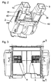
- Fig. 1 1 shows an embodiment of a blower arrangement 1 according to the invention. It essentially comprises a blower housing 2 in which a double blower 4 formed by two blowers is arranged. On the output side, the blower arrangement has two blower channels 7, 8 separated from one another.
- the double fan 4 is driven by means of an electric motor 5, wherein both fans are driven by the common electric motor 5.
- the double fan 4 is connected on the input side with two separate intake channels 9, 10.
- the respective intake channel 9, 10 serves to feed one of the two fans with an associated intake stream.
- the double fan 4 is connected on the output side to the exhaust channels 7, 8.
- Fig. 2 shows a perspective view from below of an embodiment of the blower arrangement according to the invention, in which on the underside of the blower housing 2 on each side in the region of the intake ports 9, 10 each a recirculating air flap 40 is arranged.
- the recirculation flaps 40 are each actuated by an associated lever mechanism 35, 36.
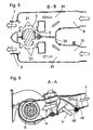
- Fig. 3 shows a front view of an embodiment according to an embodiment of the present invention.
- the two blowers of the double blower 4 are driven by a common blower motor 5.
- Fig. 4 shows a sectional view from the side of an embodiment of the blower arrangement according to the invention along the section line AA.
- the recirculating air flaps 40 are arranged and each pivotably mounted about their pivot axis 48, which is arranged substantially at one end of the circulating air cap 40.
- the recirculation flaps 40 are in a position in which the opening cross-section of the recirculation inlet is closed.
- a blower control device 17 is arranged, which in particular controls the speed of the blower motor, but can also take on further tasks for the operation of the blower arrangement.
- the direction and course of the airflow from the front air conditioner (airflow F) to an intake duct to the blower is indicated by arrows.
- the direction of this air flow is slightly inclined in this embodiment of the invention blower arrangement relative to the horizontal.
- Fig. 5 is a section through an embodiment of the blower arrangement according to the invention along the section line BB according to Fig. 4 represents.
- blower housing 2 blower motor 5 and each impeller 3 of a blower, a plurality of annular gaps 21 is formed, which each serve between the impeller 3 and blower motor 5 for the suction of the inner floods.
- a partition wall 20 is formed, which in this area of the suction chambers 24, 25 keep the incoming air streams from the intake ports 9, 10 and possibly the opening cross sections of the outside air inlet separated. This can be in the rear area, z. B.
- the left and right side of the footwell in the rear or in the area of the B-pillar separately air-conditioned separately air-conditioned.
- the direction of the incoming and outgoing air flows is again shown schematically with the help of arrows.
- the air streams at the inlets and the outlets are substantially parallel to each other.
- Fig. 6 is a section of an embodiment of the blower according to the invention according to Fig. 4 shown, wherein the recirculating air flap 40 has been pivoted about the pivot axis 48 such that the recirculating air flap 40 is now in the position for the partial recirculation mode of the fan assembly.
- the fan assembly is supplied with airflow F from the front air conditioner (not shown).
- the recirculating air flap 40 a gap between the recirculating air flap 40 and the inside of the intake passage is formed, so that still a proportion of preconditioned air from the front air conditioner after passing the recirculation flap 40 in the main flow direction can flow to the blower.
- air flow U The largest amount of air (air flow U) is absorbed by the opening cross-section on the underside of the intake duct and fed to the double fan 4.
- the recirculating air flap 40 completely block the supply of preconditioned fresh air (airflow F) from the front air conditioner in the main flow direction to the fan, so that an air flow is absorbed substantially only by the opening cross section on the underside of the intake duct.
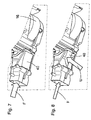
- Fig. 7 shows a perspective view from below of an embodiment of the blower device according to the invention for the mode, in the preconditioned air from the front air conditioner (air flow F) is supplied.
- air flow F air flow
- the wheels 3 of the double fan 4 are each received in a spiral 16, so that the double fan 4 is completely closed from the environment.
- the recirculation flap 40 prevents in this position, that air in the region of the opening cross-section of the recirculation inlet on the underside of the fan housing 2 can occur.
- Fig. 8 shows a perspective view seen from below an embodiment according to Fig. 7 the blower arrangement for the partial recirculation mode in which the recirculation flap 40 with respect to the position of Fig. 7 was pivoted so that in addition to the air flow from the front air conditioner (air flow F) and an air flow through the opening cross section in the region of the recirculation air inlet (air flow U) can occur.
- air flow F front air conditioner
- air flow U air flow
- Fig. 9 shows a recirculating air flap 40 according to the invention for the recirculation air intake on the left side of the fan assembly, which increases or decreases the opening cross section of the recirculation air intake depending on their position.
- the recirculation flap 40 is designed as a one-piece component.
- the recirculating air flap 40 has at one end a substantially cylindrical holder 46, in the interior of which a receptacle 41 is formed.
- the receptacle 41 is formed by a recess which extends along the longitudinal axis of the holder 46 and has a substantially square cross-section.
- a plurality of stiffening ribs 44 are formed, which extend essentially to the other end region of the recirculating-air flap 40 in its longitudinal direction.
- the height of the stiffening ribs 44 is maximum in the area of the receptacle 46 and decreases up to the receptacle 46 on the opposite side of the recirculating-air flap 40.
- Each stiffening rib 44 has an upper edge, the shape of which is bent.
- At a transverse end of the recirculating air flap 40 is of this Traverse transverse in the transverse direction of the recirculation flap 40 to the interior spaced apart a flap fin 42 formed whose design is substantially triangular-shaped.
- the flap fin 42 is bounded toward the interior of the recirculation flap 40 by a fin inner wall 45, which extends from one end of the recirculation flap 40 substantially to the region of the holder 46.
- a fin bar 43rd On the upper side of the flap fin 42 extends in the transverse direction of the fin inner wall 45 to a transverse end of the recirculating air flap 40.
- Fig. 10 shows a perspective view of the recirculating air flap 40 according to Fig. 9 , On the fins inner wall 45 opposite side of the fin 42, the substantially triangular-shaped fin outer wall 47 extends.
- Fig. 11 an embodiment of the blower arrangement 1 according to the invention is shown:
- the blower arrangement is connected to an additional air conditioner 100, which has at least one evaporator 101 and at least one radiator 102 for the air conditioning of the exiting air streams from the blower assembly 1.
- the auxiliary air conditioner 100 has at one end a plurality of air outlet channels, which include channels for the rear ventilation 105, for the ventilation of the footwell in the rear 103 and for the ventilation of the area of the B-pillar 104.
- the mounting position of this module is as in Fig. 11 shown substantially in the longitudinal direction of the vehicle.
Landscapes
- Physics & Mathematics (AREA)
- Thermal Sciences (AREA)
- Engineering & Computer Science (AREA)
- Mechanical Engineering (AREA)
- Structures Of Non-Positive Displacement Pumps (AREA)
- Air-Conditioning For Vehicles (AREA)
Abstract
Description
Die Erfindung betrifft eine Gebläseanordnung, welche in der Klimaanlage eines Kraftfahrzeugs angeordnet ist.The invention relates to a blower arrangement, which is arranged in the air conditioning system of a motor vehicle.
Klimaanlagen für Kraftfahrzeuge sorgen für eine Zufuhr von klimatisch aufbereiteter Luft in den Innenraum des Kraftfahrzeugs, wo sie in der Regel im Bereich des Armaturenbretts aus dem Klimagerät austritt. Einzelne Auslässe sind insbesondere im Fußbereich, im Mittelbereich und nahe der Innenseite der Windschutzscheibe angeordnet. Klimaanlagen werden zumeist im Frischluftmodus betrieben, wobei Luft aus der Umgebung (zumeist im Bereich unterhalb der Windschutzscheibe) angesaugt, klimatisch aufbereitet und anschließend dem Innenraum zugeführt wird. Eine Klimaanlage kann auch im Umluftmodus betrieben werden, d. h. es wird keine Luft von außen zugeführt, sondern im Innenraum angesaugt, aufbereitet und wieder dem Innenraum zugeführt.Air conditioning systems for motor vehicles provide a supply of climatically treated air in the interior of the motor vehicle, where it usually exits the air conditioner in the area of the dashboard. Individual outlets are arranged in particular in the foot region, in the middle region and near the inside of the windshield. Air conditioning systems are usually operated in fresh air mode, with air from the environment (usually in the area below the windshield) sucked, conditioned climatic and then fed to the interior. An air conditioner can be operated in the recirculation mode, ie it is no air supplied from the outside, but sucked in the interior, treated and fed back into the interior.
Bei Fahrzeugen der Oberklasse oder bei Fahrzeugen mit einem großen Innenraum wird häufig ein Zusatzklimagerät eingesetzt, welches zumeist im hinteren Bereich der Mittelkonsole angeordnet ist, und insbesondere dem Fondbereich klimatisierte Luft zuführt. Diese arbeiten aufgrund des begrenzten Einbauraums in der Regel jedoch nur im Umluftbetrieb.In luxury vehicles or in vehicles with a large interior, an additional air conditioning unit is often used, which is usually arranged in the rear area of the center console, and in particular the conditioned air supplies air to the rear area. As a rule, however, these work only in recirculation mode due to the limited installation space.
Eine Versorgung des Fondbereichs mit vorkonditionierter Frischluft von dem Frontklimagerät ist bislang vor allem unter Verwendung eines Zusatzgebläses in der Mittelkonsole bekannt. Die Luftführung vom Frontklimagerät ausgehend bis zum Fondbereich erfolgt hierbei in der Regel in zwei klimatisch getrennten Kanälen, bevor die klimatisierte Luft, insbesondere in den Fußraum im Fond, im Bereich der B-Säule ausgegeben wird. Im Fond des Fahrzeugs kann dann auch für jede Seite des Fahrzeugs eine unterschiedliche Temperatur ausgewählt und die entsprechend klimatisierte Luft abgegeben werden. Ein zusätzlicher Umluftbetrieb ist hierbei nicht möglich.Supplying the rear area with preconditioned fresh air from the front air conditioning unit has hitherto been known above all using an additional fan in the center console. The air flow from the front air conditioner starting up to the rear area usually takes place in two climatically separated channels, before the conditioned air, in particular in the footwell in the rear, is spent in the area of the B-pillar. In the rear of the vehicle can then be selected for each side of the vehicle, a different temperature and the corresponding conditioned air are discharged. An additional recirculation mode is not possible here.
Aus der
Der Komfort von Zusatzklimageräten lässt sich steigern, wenn diese mit Frischluft versorgt und somit zusätzlich im Frischluftmodus betrieben werden können. Hierbei ist es aus aufgrund des verfügbaren Bauraums im Mitteftunnel und aus energetischen Gründen für die Dimensionierung der erforderlichen Größe der Wärmetauscher besonders vorteilhaft, wenn das Zusatzklimagerät mit bereits vorkonditionierter Luft aus dem Frontklimagerät versorgt werden kann.The comfort of additional air conditioning units can be increased if they are supplied with fresh air and thus can additionally be operated in fresh air mode. Here it is due to the available space in the middle tunnel and for energy reasons for the dimensioning of the required Size of the heat exchanger particularly advantageous if the additional air conditioner can be supplied with already preconditioned air from the front air conditioner.
Der Erfindung liegt die Aufgabe zugrunde, eine verbesserte Gebläseanordnung zur Belüftung eines Kraftfahrzeugs zur Verfügung zu stellen, welche eine gute Ausnutzung des Bauraums, einen erhöhten Komfort für die Insassen und verbesserte akustische Eigenschaften im Betrieb aufweist.The invention has for its object to provide an improved fan assembly for ventilation of a motor vehicle available, which has a good utilization of space, increased comfort for the occupants and improved acoustic properties during operation.
Diese Aufgabe wird erfindungsgemäß durch die Gebläseanordnung gemäß Anspruch 1 gelöst. Vorteilhafte Weiterbildungen sind Gegenstand der Unteransprüche.This object is achieved by the blower arrangement according to
Eine erfindungsgemäße Gebläseanordnung, insbesondere zur Belüftung eines Kraftfahrzeuges, weist ein von einem Gebläsemotor angetriebenes Gebläse mit wenigstens einem, vorzugsweise mindestens zwei Gebläserädem auf. Des Weiteren weist die erfindungsgemäße Gebläseanordnung eingangsseitig wenigstens einen Ansaugkanal, der mit einer Ansaugöffnung versehen ist, und ausgangsseitig wenigstens einen, vorzugsweise zwei Ausblaskanäle auf. Dieser wenigstens eine Ansaugkanal weist einen von dieser Ansaugöffnung im Wesentlichen getrennten Öffnungsquerschnitt zur Aufnahme von Umluft auf, und es ist weiterhin vorgesehen, dass dessen Öffnungsquerschnitt mittels eines Steuerelements veränderbar ist.A blower arrangement according to the invention, in particular for ventilating a motor vehicle, has a blower driven by a blower motor with at least one, preferably at least two blower wheels. Furthermore, the blower arrangement according to the invention has on the input side at least one intake duct which is provided with a suction opening, and on the output side at least one, preferably two blow-out ducts. This at least one intake duct has an opening cross-section substantially separated from this intake opening for receiving circulating air, and it is further provided that its opening cross-section can be changed by means of a control element.
Diese Gestaltung des wenigstens einen Ansaugkanals ermöglicht es vorteilhafterweise, den Betrieb der Gebläseanordnung um den Frischluftmodus zu erweitern, wodurch es möglich wird, dass insbesondere die Passagiere im Fond des Fahrzeugs mit Frischluft versorgt werden. Dies stellt einen erheblichen Komfortgewinn für die Insassen dar.This design of the at least one intake channel advantageously makes it possible to extend the operation of the fan assembly by the fresh air mode, which makes it possible that in particular the passengers in the rear of the vehicle are supplied with fresh air. This represents a significant gain in comfort for the occupants.
In einer bevorzugten Ausführungsform der erfindungsgemäßen Gebläseanordnung ist das Steuerelement vorzugsweise eine Klappe. Es sind aber auch andere Gestaltungen für das Steuerelement denkbar, beispielweise vorzugsweise Bänder mit unterschiedlich gestalteten Aussparungen, wobei sich die Bänder in Längsrichtung verschieben lassen und mit einem Element derart zusammenwirken, dass unterschiedliche Öffnungsquerschnitte freigegeben oder verschlossen werden. Des Weiteren können unterschiedliche Klappengeometrien eingesetzt werden.In a preferred embodiment of the blower arrangement according to the invention, the control element is preferably a flap. But there are also other designs for the control conceivable, for example, preferably bands with differently shaped recesses, wherein the bands can be moved in the longitudinal direction and cooperate with an element such that different opening cross-sections are released or closed. Furthermore, different flap geometries can be used.
In einer bevorzugten Ausführungsform der erfindungsgemäßen Gebläseanordnung ist eine Umluftklappe bevorzugt um eine Schwenkachse gelagert. Die Umluftklappe ist vorzugsweise im Gebläsegehäuse gelagert, kann in einer weiteren Ausführungsform der Gebläseanordnung auch bevorzugt au-βerhalb des Gebläsegehäuses gelagert sein. Die Stellung der Umluftklappe ist vorzugsweise kontinuierlich veränderbar, kann aber in einer weiteren Ausführungsform bevorzugt mit Hilfe einer veränderten kinematischen Gestaltung für deren Betätigung diskontinuierlich veränderbar sein.In a preferred embodiment of the blower arrangement according to the invention, a recirculation flap is preferably mounted about a pivot axis. The recirculation damper is preferably mounted in the blower housing, in a further embodiment of the blower arrangement may also preferably be mounted outside the blower housing. The position of the recirculating air flap is preferably continuously variable, but in a further embodiment may preferably be discontinuously changeable with the aid of a modified kinematic design for the actuation thereof.
In einer bevorzugten Ausführungsform der erfindungsgemäßen Gebläseanordnung geben die Ausblaskanäle die aus diesen austretenden, bevorzugt voneinander getrennten Luftströme vorzugsweise im Wesentlichen in horizontaler Richtung ab.In a preferred embodiment of the blower arrangement according to the invention, the blow-off channels preferably discharge the air streams emerging from them, preferably separate from one another, essentially in the horizontal direction.
Hierbei ergibt sich gegenüber bekannten Gebläseanordnungen nach dem Stand der Technik der Vorteil, dass der vorhandene Bauraum im Bereich der Mittelkonsole für die Gebläseanordnung besonders gut genutzt wird, da bei im Wesentlichen identischen Abmaßen in Längs- und Querrichtung der Gebläseanordnung gegenüber dem Stand der Technik eine signifikante Verbesserung des Komforts durch den zusätzlichen Frischluftmodus erreicht wird.This results in comparison to known blower arrangements according to the prior art, the advantage that the available space in the center console for the fan assembly is particularly well used, since at substantially identical dimensions in the longitudinal and transverse directions of the fan assembly over the prior art, a significant Improvement of comfort is achieved by the additional fresh air mode.
In einer bevorzugten Ausführungsform der erfindungsgemäßen Gebläseanordnung wird bevorzugt wenigstens eine Umluftklappe von wenigstens einem Hebelmechanismus betätigt. In einer weiteren Ausführungsform sind bevorzugt eine Vielzahl von Umluftklappen über vorzugsweise jeweils einen eigenen Hebelmechanismus bevorzugt separat betätigbar, so dass die Flexibilität der Gebläseanordnung im Frischluftmodus noch gesteigert werden kann. Damit lassen sich die einzelnen Ansaugkanäle je nach Wunsch in einer individuellen Betriebsart einstellen.In a preferred embodiment of the blower arrangement according to the invention, at least one circulating-air flap is preferably actuated by at least one lever mechanism. In a further embodiment, a plurality of recirculating air flaps are preferably preferably actuatable separately, preferably each with its own lever mechanism, so that the flexibility of the blower arrangement in the fresh air mode can still be increased. This allows the individual intake ports to be set in an individual operating mode as desired.
In einer bevorzugten Ausführungsform der erfindungsgemäßen Gebläseanordnung ist der Öffnungsquerschnitt zur Aufnahme von Umluft eines Ansaugkanals vorzugsweise im Wesentlichen auf einer Unterseite des Gebläsegehäuses angeordnet, so dass die Umluft im Wesentlichen von unten, beispielsweise zwischen einem Fahrzeugmitteltunnel und dem Gebläsegehäuse aufgenommen wird. Hieraus ergeben sich deutlich verminderte Geräusche im Innenraum des Fahrzeugs, da eine direkte Schallabstrahlung im Bereich des Öffnungsquerschnitts der Umluftklappe von den Bauteilen des Fahrzeugtunnels reflektiert und ein Teil des Schalls absorbiert wird.In a preferred embodiment of the blower arrangement according to the invention, the opening cross section for receiving circulating air of an intake duct is preferably arranged substantially on an underside of the blower housing, so that the circulating air is received substantially from below, for example between a vehicle center tunnel and the blower housing. This results in significantly reduced noise in the interior of the vehicle, as a direct sound radiation in the region of the opening cross section of the recirculation flap of the components of the vehicle tunnel reflected and a part of the sound is absorbed.
Die Ausblaskanäle sind bevorzugt getrennt voneinander ausgebildet, wobei diese in einer bevorzugten Ausführungsform der erfindungsgemäßen Gebläseanordnung die aus der Gebläseanordnung austretenden, voneinander getrennten Luftströme vorzugsweise im Wesentlichen in horizontaler Richtung abgeben. Die Trennung der Ausblaskanäle ermöglicht vorteilhafterweise eine Abgabe von Luftströmen mit unterschiedlicher Temperatur aus der Gebläseanordnung in den Fondbereich des Fahrzeugs. Dadurch wird der Komfort für die Insassen gesteigert.The blow-out channels are preferably formed separately from one another, and in a preferred embodiment of the blower arrangement according to the invention, they deliver the air streams which are separated from the blower arrangement, preferably in a substantially horizontal direction. The separation of the blow-off channels advantageously makes it possible to dispense air streams of different temperature from the blower arrangement into the rear region of the vehicle. This increases the comfort for the occupants.
Vorzugsweise sind in einer bevorzugten Ausführungsform der erfindungsgemäßen Gebläseanordnung im Gebläsegehäuse bevorzugt wenigstens zwei Ansaugräume ausgebildet, die bevorzugt durch eine Trennwand bevorzugt voneinander getrennt werden. Dadurch ist es möglich, die von dem Frontklimagerät aufgenommenen Luftströme durch die Ansaugkanäle hindurch bis zu den Ausblaskanälen auch innerhalb des Gebläsegehäuses getrennt zu führen.Preferably, in a preferred embodiment of the fan assembly according to the invention in the fan housing are preferably at least formed two suction chambers, which are preferably preferably separated from each other by a partition. This makes it possible to separate the air streams taken in by the front air conditioner through the intake ducts as far as the blow-off ducts and also inside the blower housing.
Bei dem Gebläsegehäuse handelt es sich vorzugsweise um ein Kunststoffgehäuse.The blower housing is preferably a plastic housing.
Der Gebläsemotor ist bevorzugt gekapselt ausgeführt ist, wodurch die erforderliche Drucksituation zur Ansaugung der Luftströme im Gebläsegehäuse erreicht wird. Es ist vorzugsweise ein einzelner Gebläsemotor zum Antrieb des Doppelgebläses vorgesehen, wobei der Gebläsemotor vorzugsweise ein Elektromotor ist. Dies führt vorteilhafterweise zu einer Reduzierung der Motorgeräusche und erhöht damit den Komfort für die Insassen des Fahrzeugs. In einer weiteren Ausführungsform kann beispielsweise in je einem Ausblaskanal ein separater Gebläsemotor, welcher mindestens ein Laufrad aufweist, ausgebildet sein.The blower motor is preferably executed encapsulated, whereby the required pressure situation for suction of the air streams is achieved in the blower housing. There is preferably provided a single fan motor for driving the double fan, wherein the fan motor is preferably an electric motor. This advantageously leads to a reduction of the engine noise and thus increases the comfort for the occupants of the vehicle. In a further embodiment, for example, in each case a blower motor, a separate blower motor, which has at least one impeller, be formed.
In einer bevorzugten Ausführungsform der erfindungsgemäßen Gebläseanordnung sind die einzelnen Gebläse des Doppelgebläses vorzugsweise einflutig und / oder mehrflutig ausgeführt. Unter Flutigkeit wird bei Radialgebläsen die Anzahl der Ansaugwege verstanden.In a preferred embodiment of the blower arrangement according to the invention, the individual blowers of the double blower are preferably designed to be single-flow and / or multi-flow. In the case of radial blowers, flooding refers to the number of suction paths.
Die Laufradnaben eines einflutig oder mehrflutig ausgeführten Gebläses des Doppelgebläses sind bevorzugt mit Durchbrüchen versehen.The impeller hubs of a single-flow or multi-flow blower of the double fan are preferably provided with openings.
In einer bevorzugten Ausführungsform der erfindungsgemäßen Gebläseanordnung sind die Laufräder des Doppelgebläses bevorzugt verdrehfest mit einer Abtriebswelle des Gebläsemotors verbunden.In a preferred embodiment of the blower arrangement according to the invention, the impellers of the double blower are preferably rotationally connected to an output shaft of the blower motor.
In einer bevorzugten Ausführungsform der erfindungsgemäßen Gebläseanordnung ist vorzugsweise eine Gebläsesteuereinrichtung zur Steuerung und/oder Regelung der Drehzahl des Gebläses vorhanden, welche bevorzugt innerhalb des Gebläsegehäuses angeordnet ist.In a preferred embodiment of the blower arrangement according to the invention, a blower control device is preferably provided for controlling and / or regulating the rotational speed of the blower, which is preferably arranged inside the blower housing.
In einer besonders bevorzugten Ausführungsform der erfindungsgemäßen Gebläseanordnung wird vorzugsweise ein Teil des Luftmassenstroms in die Gebläsemotorkapselung zur Kühlung des Gebläsemotors und / oder der Steuereinheit geleitet.In a particularly preferred embodiment of the blower arrangement according to the invention, a part of the air mass flow is preferably conducted into the blower motor encapsulation for cooling the blower motor and / or the control unit.
Im Folgenden sollen nun beispielhafte Ausführungsformen der Erfindung anhand der Figuren näher erläutert werden. Es zeigt:
- Fig. 1
- eine perspektivische Ansicht einer Gebläseanordnung nach einer Ausführungsform der vorliegenden Erfindung,
- Fig. 2
- eine perspektivische Ansicht von unten gesehen einer erfindungsgemäßen Gebläseanordnung,
- Fig. 3
- eine Vorderansicht einer Gebläseanordnung nach einer Ausführungsform der vorliegenden Erfindung,
- Fig. 4
- eine Schnittansicht von der Seite einer Ausführungsform der Gebläseanordnung entlang der Schnittlinie A-A,
- Fig. 5
- eine Schnittansicht von oben gesehen einer Ausführungsform der Gebläseanordnung entlang der Schnittlinie B-B,
- Fig. 6
- eine Schnittdarstellung einer Ausführungsform der Gebläseanordnung gemäß
Fig. 4 , - Fig. 7
- eine perspektivische Ansicht von unten gesehen einer Ausführungsform der Gebläseanordnung für einen Modus, in dem Luft vom Frontklimagerät zugeführt wird,
- Fig. 8
- eine perspektivische Ansicht von unten gesehen einer Ausführungsform gemäß
Fig. 7 der Gebläseanordnung für den Teilumluftmodus, - Fig. 9
- eine perspektivische Darstellung für eine Umluftklappe zur Steuerung des Lufteinlass im Ansaugbereich,
- Fig 10
- eine perspektivische Darstellung für eine Umluftklappe gemäß
Fig. 9 und - Fig. 11
- eine perspektivische Darstellung für die Gebläseanordnung, welche mit einem Zusatzklimagerät verbunden ist.
- Fig. 1
- a perspective view of a fan assembly according to an embodiment of the present invention,
- Fig. 2
- a perspective view from below of a blower arrangement according to the invention,
- Fig. 3
- a front view of a fan assembly according to an embodiment of the present invention,
- Fig. 4
- a sectional view from the side of an embodiment of the fan assembly along the section line AA,
- Fig. 5
- a sectional view seen from above an embodiment of the fan assembly along the section line BB,
- Fig. 6
- a sectional view of an embodiment of the fan assembly according to
Fig. 4 . - Fig. 7
- a perspective view from below of an embodiment of the blower arrangement for a mode in which air is supplied from the front air conditioner,
- Fig. 8
- a perspective view seen from below an embodiment according to
Fig. 7 the blower arrangement for the partial recirculation mode, - Fig. 9
- a perspective view of a recirculation damper for controlling the air intake in the intake,
- FIG. 10
- a perspective view of a recirculation damper according to
Fig. 9 and - Fig. 11
- a perspective view of the fan assembly, which is connected to a Zusatzklimagerät.
In
In
In
Claims (15)
Applications Claiming Priority (1)
| Application Number | Priority Date | Filing Date | Title |
|---|---|---|---|
| DE102007026808A DE102007026808A1 (en) | 2007-06-06 | 2007-06-06 | Blower arrangement for ventilation of a vehicle |
Publications (3)
| Publication Number | Publication Date |
|---|---|
| EP2000337A2 true EP2000337A2 (en) | 2008-12-10 |
| EP2000337A3 EP2000337A3 (en) | 2009-02-18 |
| EP2000337B1 EP2000337B1 (en) | 2012-03-21 |
Family
ID=39739331
Family Applications (1)
| Application Number | Title | Priority Date | Filing Date |
|---|---|---|---|
| EP08009045A Not-in-force EP2000337B1 (en) | 2007-06-06 | 2008-05-16 | Fan assembly for ventilating a vehicle |
Country Status (3)
| Country | Link |
|---|---|
| EP (1) | EP2000337B1 (en) |
| AT (1) | ATE550213T1 (en) |
| DE (1) | DE102007026808A1 (en) |
Cited By (7)
| Publication number | Priority date | Publication date | Assignee | Title |
|---|---|---|---|---|
| DE102014101063A1 (en) | 2014-01-29 | 2015-07-30 | Denso Automotive Deutschland Gmbh | Device for foot conditioning |
| DE102015115025A1 (en) | 2015-09-08 | 2017-03-09 | Denso Automotive Deutschland Gmbh | Ventilation device and seat with such a ventilation device, in particular for a vehicle |
| EP3144180A1 (en) | 2015-09-08 | 2017-03-22 | Denso Automotive Deutschland GmbH | Ventilation device and seat with such a ventilation device, in particular for a vehicle |
| DE102016105372A1 (en) | 2016-03-22 | 2017-09-28 | Denso Automotive Deutschland Gmbh | Ventilation device and seat with such a ventilation device, in particular for a vehicle |
| DE102016117443A1 (en) | 2016-04-29 | 2017-11-02 | Denso Automotive Deutschland Gmbh | Seat with a ventilation device and method for air conditioning the seating environment |
| WO2022259053A1 (en) * | 2021-06-08 | 2022-12-15 | Agco International Gmbh | Vehicle heating, ventilation and air conditioning system |
| FR3131869A1 (en) * | 2021-12-13 | 2023-07-21 | Valeo Systemes Thermiques | Air conditioning device for a vehicle interior |
Citations (1)
| Publication number | Priority date | Publication date | Assignee | Title |
|---|---|---|---|---|
| DE10234345A1 (en) | 2002-07-26 | 2004-02-05 | Behr Gmbh & Co. | Fan arrangement for vehicle ventilation has dual fan and at least one of two outflow channels with return element via which it can be connected to induction channel depending on situation |
Family Cites Families (11)
| Publication number | Priority date | Publication date | Assignee | Title |
|---|---|---|---|---|
| US2060069A (en) * | 1934-01-29 | 1936-11-10 | William F Hafner | Toy railway track switch |
| US2221891A (en) * | 1937-02-03 | 1940-11-19 | Fred M Young | Air conditioning device for passenger vehicles |
| JP3222375B2 (en) * | 1995-03-20 | 2001-10-29 | トヨタ自動車株式会社 | Vehicle air conditioner |
| JP3823531B2 (en) * | 1997-08-25 | 2006-09-20 | 株式会社デンソー | Air conditioner for vehicles |
| JP3834959B2 (en) * | 1997-10-13 | 2006-10-18 | 株式会社デンソー | Air conditioner for vehicles |
| JP3269467B2 (en) * | 1998-10-28 | 2002-03-25 | 株式会社デンソー | Vehicle air conditioner |
| FR2793737B1 (en) * | 1999-05-17 | 2001-07-27 | Valeo Climatisation | HEATING AND / OR AIR CONDITIONING DEVICE OF A MOTOR VEHICLE COMPRISING A REMOVABLE MOTOR-FAN GROUP |
| DE19954308C2 (en) * | 1999-11-11 | 2003-11-13 | Daimler Chrysler Ag | Air conditioning for passenger compartments of vehicles |
| FR2832023B1 (en) * | 2001-11-02 | 2004-02-20 | Valeo Climatisation | MOTOR-FAN GROUP CONTROL MODULE |
| DE102005001970B4 (en) * | 2005-01-15 | 2012-10-04 | Klaus Arold | Flap assembly for controlling the fresh and Umluftzustroms |
| DE102005019912A1 (en) * | 2005-04-27 | 2006-11-02 | Behr Gmbh & Co. Kg | Ventilation device, in particular for a motor vehicle |
-
2007
- 2007-06-06 DE DE102007026808A patent/DE102007026808A1/en not_active Withdrawn
-
2008
- 2008-05-16 EP EP08009045A patent/EP2000337B1/en not_active Not-in-force
- 2008-05-16 AT AT08009045T patent/ATE550213T1/en active
Patent Citations (1)
| Publication number | Priority date | Publication date | Assignee | Title |
|---|---|---|---|---|
| DE10234345A1 (en) | 2002-07-26 | 2004-02-05 | Behr Gmbh & Co. | Fan arrangement for vehicle ventilation has dual fan and at least one of two outflow channels with return element via which it can be connected to induction channel depending on situation |
Cited By (8)
| Publication number | Priority date | Publication date | Assignee | Title |
|---|---|---|---|---|
| DE102014101063A1 (en) | 2014-01-29 | 2015-07-30 | Denso Automotive Deutschland Gmbh | Device for foot conditioning |
| DE102015115025A1 (en) | 2015-09-08 | 2017-03-09 | Denso Automotive Deutschland Gmbh | Ventilation device and seat with such a ventilation device, in particular for a vehicle |
| EP3144180A1 (en) | 2015-09-08 | 2017-03-22 | Denso Automotive Deutschland GmbH | Ventilation device and seat with such a ventilation device, in particular for a vehicle |
| DE102016105372A1 (en) | 2016-03-22 | 2017-09-28 | Denso Automotive Deutschland Gmbh | Ventilation device and seat with such a ventilation device, in particular for a vehicle |
| DE102016117443A1 (en) | 2016-04-29 | 2017-11-02 | Denso Automotive Deutschland Gmbh | Seat with a ventilation device and method for air conditioning the seating environment |
| DE102016117443B4 (en) | 2016-04-29 | 2022-06-23 | Denso Automotive Deutschland Gmbh | Seat with a ventilation device and method for air-conditioning the area around the seat |
| WO2022259053A1 (en) * | 2021-06-08 | 2022-12-15 | Agco International Gmbh | Vehicle heating, ventilation and air conditioning system |
| FR3131869A1 (en) * | 2021-12-13 | 2023-07-21 | Valeo Systemes Thermiques | Air conditioning device for a vehicle interior |
Also Published As
| Publication number | Publication date |
|---|---|
| ATE550213T1 (en) | 2012-04-15 |
| EP2000337A3 (en) | 2009-02-18 |
| EP2000337B1 (en) | 2012-03-21 |
| DE102007026808A1 (en) | 2008-12-11 |
Similar Documents
| Publication | Publication Date | Title |
|---|---|---|
| EP2000337B1 (en) | Fan assembly for ventilating a vehicle | |
| DE112015002457T5 (en) | Air conditioning for a vehicle and control method for it | |
| DE102016116356A1 (en) | air vents | |
| EP1517807B1 (en) | Modular heating and/or air conditioning system for a motor vehicle | |
| EP0525218B1 (en) | Heating and/or airconditioning device with air mixture temperature control for a motor vehicle | |
| DE102015109354A1 (en) | Arrangement for air distribution for an air conditioning system of a motor vehicle | |
| EP1641642A1 (en) | Louvre for an air-conduction housing of a vehicle air-conditioning system | |
| DE10002951C1 (en) | Radial ventilation fan for automobile passenger compartment has 2 separate fan stages driven by central electric motor contained within respective ventialtion channels leading to floor of passenger compartment | |
| EP1531068B1 (en) | Air conditioning system for a vehicle | |
| EP1426213A2 (en) | Air-conditioning device for vehicles | |
| EP1792760B1 (en) | Air conditioner, in particular for a vehicle | |
| EP1510375B1 (en) | Air conditioning installation and method for operating one such installation | |
| DE102011102155A1 (en) | Radiator grill module for cooling radiator in body space of front end portion of motor car, has air-guidance elements redirecting part of airflow into body space region between bumper and radiator, and designed as slat-form surface elements | |
| DE10147113A1 (en) | Air conditioning and ventilation device for motor vehicles has channel element to feed part hot air flow from area with hot air concentration, to defroster outlet | |
| EP1384606B1 (en) | Blower unit and method for ventilating a vehicle | |
| EP1930193B1 (en) | Device for regulating air flow, in particular for the air conditioning system of a vehicle | |
| EP2450204B1 (en) | Air conditioning for a motor vehicle | |
| DE10234345A1 (en) | Fan arrangement for vehicle ventilation has dual fan and at least one of two outflow channels with return element via which it can be connected to induction channel depending on situation | |
| DE10350193A1 (en) | Vehicle climate control system, has foot room channel with wall separated from outside of spiral casing by insulation space | |
| DE102018113175A1 (en) | Rear air conditioner for a vehicle | |
| EP1843908B1 (en) | Motor vehicle air conditioning system | |
| EP1674308B1 (en) | Air conditioning unit, in particular an auxiliary air conditioning unit with electrical supplementary heater | |
| EP1899187B1 (en) | Air conditioning unit | |
| DE10333184A1 (en) | Ventilating device for passenger cell in motor vehicles with blower with blower spirals offset upwards and forwards on both sides, for best utilization of space | |
| EP1457369B1 (en) | Auxiliary vehicle air-conditioning unit |
Legal Events
| Date | Code | Title | Description |
|---|---|---|---|
| PUAI | Public reference made under article 153(3) epc to a published international application that has entered the european phase |
Free format text: ORIGINAL CODE: 0009012 |
|
| AK | Designated contracting states |
Kind code of ref document: A2 Designated state(s): AT BE BG CH CY CZ DE DK EE ES FI FR GB GR HR HU IE IS IT LI LT LU LV MC MT NL NO PL PT RO SE SI SK TR |
|
| AX | Request for extension of the european patent |
Extension state: AL BA MK RS |
|
| PUAL | Search report despatched |
Free format text: ORIGINAL CODE: 0009013 |
|
| AK | Designated contracting states |
Kind code of ref document: A3 Designated state(s): AT BE BG CH CY CZ DE DK EE ES FI FR GB GR HR HU IE IS IT LI LT LU LV MC MT NL NO PL PT RO SE SI SK TR |
|
| AX | Request for extension of the european patent |
Extension state: AL BA MK RS |
|
| 17P | Request for examination filed |
Effective date: 20090818 |
|
| 17Q | First examination report despatched |
Effective date: 20090909 |
|
| AKX | Designation fees paid |
Designated state(s): AT BE BG CH CY CZ DE DK EE ES FI FR GB GR HR HU IE IS IT LI LT LU LV MC MT NL NO PL PT RO SE SI SK TR |
|
| GRAP | Despatch of communication of intention to grant a patent |
Free format text: ORIGINAL CODE: EPIDOSNIGR1 |
|
| GRAS | Grant fee paid |
Free format text: ORIGINAL CODE: EPIDOSNIGR3 |
|
| GRAA | (expected) grant |
Free format text: ORIGINAL CODE: 0009210 |
|
| AK | Designated contracting states |
Kind code of ref document: B1 Designated state(s): AT BE BG CH CY CZ DE DK EE ES FI FR GB GR HR HU IE IS IT LI LT LU LV MC MT NL NO PL PT RO SE SI SK TR |
|
| REG | Reference to a national code |
Ref country code: GB Ref legal event code: FG4D Free format text: NOT ENGLISH |
|
| REG | Reference to a national code |
Ref country code: CH Ref legal event code: EP |
|
| REG | Reference to a national code |
Ref country code: IE Ref legal event code: FG4D Free format text: LANGUAGE OF EP DOCUMENT: GERMAN |
|
| REG | Reference to a national code |
Ref country code: AT Ref legal event code: REF Ref document number: 550213 Country of ref document: AT Kind code of ref document: T Effective date: 20120415 |
|
| REG | Reference to a national code |
Ref country code: DE Ref legal event code: R096 Ref document number: 502008006718 Country of ref document: DE Effective date: 20120516 |
|
| REG | Reference to a national code |
Ref country code: NL Ref legal event code: VDEP Effective date: 20120321 |
|
| PG25 | Lapsed in a contracting state [announced via postgrant information from national office to epo] |
Ref country code: HR Free format text: LAPSE BECAUSE OF FAILURE TO SUBMIT A TRANSLATION OF THE DESCRIPTION OR TO PAY THE FEE WITHIN THE PRESCRIBED TIME-LIMIT Effective date: 20120321 Ref country code: LT Free format text: LAPSE BECAUSE OF FAILURE TO SUBMIT A TRANSLATION OF THE DESCRIPTION OR TO PAY THE FEE WITHIN THE PRESCRIBED TIME-LIMIT Effective date: 20120321 Ref country code: NO Free format text: LAPSE BECAUSE OF FAILURE TO SUBMIT A TRANSLATION OF THE DESCRIPTION OR TO PAY THE FEE WITHIN THE PRESCRIBED TIME-LIMIT Effective date: 20120621 |
|
| LTIE | Lt: invalidation of european patent or patent extension |
Effective date: 20120321 |
|
| PG25 | Lapsed in a contracting state [announced via postgrant information from national office to epo] |
Ref country code: FI Free format text: LAPSE BECAUSE OF FAILURE TO SUBMIT A TRANSLATION OF THE DESCRIPTION OR TO PAY THE FEE WITHIN THE PRESCRIBED TIME-LIMIT Effective date: 20120321 Ref country code: LV Free format text: LAPSE BECAUSE OF FAILURE TO SUBMIT A TRANSLATION OF THE DESCRIPTION OR TO PAY THE FEE WITHIN THE PRESCRIBED TIME-LIMIT Effective date: 20120321 Ref country code: GR Free format text: LAPSE BECAUSE OF FAILURE TO SUBMIT A TRANSLATION OF THE DESCRIPTION OR TO PAY THE FEE WITHIN THE PRESCRIBED TIME-LIMIT Effective date: 20120622 |
|
| PG25 | Lapsed in a contracting state [announced via postgrant information from national office to epo] |
Ref country code: CY Free format text: LAPSE BECAUSE OF FAILURE TO SUBMIT A TRANSLATION OF THE DESCRIPTION OR TO PAY THE FEE WITHIN THE PRESCRIBED TIME-LIMIT Effective date: 20120321 |
|
| PG25 | Lapsed in a contracting state [announced via postgrant information from national office to epo] |
Ref country code: SI Free format text: LAPSE BECAUSE OF FAILURE TO SUBMIT A TRANSLATION OF THE DESCRIPTION OR TO PAY THE FEE WITHIN THE PRESCRIBED TIME-LIMIT Effective date: 20120321 Ref country code: SE Free format text: LAPSE BECAUSE OF FAILURE TO SUBMIT A TRANSLATION OF THE DESCRIPTION OR TO PAY THE FEE WITHIN THE PRESCRIBED TIME-LIMIT Effective date: 20120321 Ref country code: EE Free format text: LAPSE BECAUSE OF FAILURE TO SUBMIT A TRANSLATION OF THE DESCRIPTION OR TO PAY THE FEE WITHIN THE PRESCRIBED TIME-LIMIT Effective date: 20120321 Ref country code: PL Free format text: LAPSE BECAUSE OF FAILURE TO SUBMIT A TRANSLATION OF THE DESCRIPTION OR TO PAY THE FEE WITHIN THE PRESCRIBED TIME-LIMIT Effective date: 20120321 Ref country code: RO Free format text: LAPSE BECAUSE OF FAILURE TO SUBMIT A TRANSLATION OF THE DESCRIPTION OR TO PAY THE FEE WITHIN THE PRESCRIBED TIME-LIMIT Effective date: 20120321 Ref country code: IS Free format text: LAPSE BECAUSE OF FAILURE TO SUBMIT A TRANSLATION OF THE DESCRIPTION OR TO PAY THE FEE WITHIN THE PRESCRIBED TIME-LIMIT Effective date: 20120721 Ref country code: CZ Free format text: LAPSE BECAUSE OF FAILURE TO SUBMIT A TRANSLATION OF THE DESCRIPTION OR TO PAY THE FEE WITHIN THE PRESCRIBED TIME-LIMIT Effective date: 20120321 |
|
| BERE | Be: lapsed |
Owner name: BEHR G.M.B.H. & CO. KG Effective date: 20120531 |
|
| PG25 | Lapsed in a contracting state [announced via postgrant information from national office to epo] |
Ref country code: SK Free format text: LAPSE BECAUSE OF FAILURE TO SUBMIT A TRANSLATION OF THE DESCRIPTION OR TO PAY THE FEE WITHIN THE PRESCRIBED TIME-LIMIT Effective date: 20120321 Ref country code: PT Free format text: LAPSE BECAUSE OF FAILURE TO SUBMIT A TRANSLATION OF THE DESCRIPTION OR TO PAY THE FEE WITHIN THE PRESCRIBED TIME-LIMIT Effective date: 20120723 |
|
| PG25 | Lapsed in a contracting state [announced via postgrant information from national office to epo] |
Ref country code: MC Free format text: LAPSE BECAUSE OF NON-PAYMENT OF DUE FEES Effective date: 20120531 |
|
| REG | Reference to a national code |
Ref country code: CH Ref legal event code: PL |
|
| PLBE | No opposition filed within time limit |
Free format text: ORIGINAL CODE: 0009261 |
|
| STAA | Information on the status of an ep patent application or granted ep patent |
Free format text: STATUS: NO OPPOSITION FILED WITHIN TIME LIMIT |
|
| PG25 | Lapsed in a contracting state [announced via postgrant information from national office to epo] |
Ref country code: DK Free format text: LAPSE BECAUSE OF FAILURE TO SUBMIT A TRANSLATION OF THE DESCRIPTION OR TO PAY THE FEE WITHIN THE PRESCRIBED TIME-LIMIT Effective date: 20120321 Ref country code: NL Free format text: LAPSE BECAUSE OF FAILURE TO SUBMIT A TRANSLATION OF THE DESCRIPTION OR TO PAY THE FEE WITHIN THE PRESCRIBED TIME-LIMIT Effective date: 20120321 Ref country code: CH Free format text: LAPSE BECAUSE OF NON-PAYMENT OF DUE FEES Effective date: 20120531 Ref country code: LI Free format text: LAPSE BECAUSE OF NON-PAYMENT OF DUE FEES Effective date: 20120531 |
|
| 26N | No opposition filed |
Effective date: 20130102 |
|
| REG | Reference to a national code |
Ref country code: IE Ref legal event code: MM4A |
|
| PG25 | Lapsed in a contracting state [announced via postgrant information from national office to epo] |
Ref country code: IT Free format text: LAPSE BECAUSE OF FAILURE TO SUBMIT A TRANSLATION OF THE DESCRIPTION OR TO PAY THE FEE WITHIN THE PRESCRIBED TIME-LIMIT Effective date: 20120321 Ref country code: BE Free format text: LAPSE BECAUSE OF NON-PAYMENT OF DUE FEES Effective date: 20120531 |
|
| REG | Reference to a national code |
Ref country code: DE Ref legal event code: R097 Ref document number: 502008006718 Country of ref document: DE Effective date: 20130102 |
|
| PG25 | Lapsed in a contracting state [announced via postgrant information from national office to epo] |
Ref country code: ES Free format text: LAPSE BECAUSE OF FAILURE TO SUBMIT A TRANSLATION OF THE DESCRIPTION OR TO PAY THE FEE WITHIN THE PRESCRIBED TIME-LIMIT Effective date: 20120702 Ref country code: IE Free format text: LAPSE BECAUSE OF NON-PAYMENT OF DUE FEES Effective date: 20120516 |
|
| PG25 | Lapsed in a contracting state [announced via postgrant information from national office to epo] |
Ref country code: MT Free format text: LAPSE BECAUSE OF FAILURE TO SUBMIT A TRANSLATION OF THE DESCRIPTION OR TO PAY THE FEE WITHIN THE PRESCRIBED TIME-LIMIT Effective date: 20120321 Ref country code: BG Free format text: LAPSE BECAUSE OF FAILURE TO SUBMIT A TRANSLATION OF THE DESCRIPTION OR TO PAY THE FEE WITHIN THE PRESCRIBED TIME-LIMIT Effective date: 20120621 |
|
| PG25 | Lapsed in a contracting state [announced via postgrant information from national office to epo] |
Ref country code: TR Free format text: LAPSE BECAUSE OF FAILURE TO SUBMIT A TRANSLATION OF THE DESCRIPTION OR TO PAY THE FEE WITHIN THE PRESCRIBED TIME-LIMIT Effective date: 20120321 |
|
| PG25 | Lapsed in a contracting state [announced via postgrant information from national office to epo] |
Ref country code: LU Free format text: LAPSE BECAUSE OF NON-PAYMENT OF DUE FEES Effective date: 20120516 |
|
| REG | Reference to a national code |
Ref country code: AT Ref legal event code: MM01 Ref document number: 550213 Country of ref document: AT Kind code of ref document: T Effective date: 20130516 |
|
| PG25 | Lapsed in a contracting state [announced via postgrant information from national office to epo] |
Ref country code: HU Free format text: LAPSE BECAUSE OF FAILURE TO SUBMIT A TRANSLATION OF THE DESCRIPTION OR TO PAY THE FEE WITHIN THE PRESCRIBED TIME-LIMIT Effective date: 20080516 |
|
| PG25 | Lapsed in a contracting state [announced via postgrant information from national office to epo] |
Ref country code: AT Free format text: LAPSE BECAUSE OF NON-PAYMENT OF DUE FEES Effective date: 20130516 |
|
| REG | Reference to a national code |
Ref country code: DE Ref legal event code: R082 Ref document number: 502008006718 Country of ref document: DE Representative=s name: GRAUEL, ANDREAS, DIPL.-PHYS. DR. RER. NAT., DE |
|
| REG | Reference to a national code |
Ref country code: DE Ref legal event code: R082 Ref document number: 502008006718 Country of ref document: DE Representative=s name: GRAUEL, ANDREAS, DIPL.-PHYS. DR. RER. NAT., DE Effective date: 20150317 Ref country code: DE Ref legal event code: R081 Ref document number: 502008006718 Country of ref document: DE Owner name: MAHLE INTERNATIONAL GMBH, DE Free format text: FORMER OWNER: BEHR GMBH & CO. KG, 70469 STUTTGART, DE Effective date: 20150317 |
|
| REG | Reference to a national code |
Ref country code: FR Ref legal event code: PLFP Year of fee payment: 9 |
|
| REG | Reference to a national code |
Ref country code: FR Ref legal event code: PLFP Year of fee payment: 10 |
|
| REG | Reference to a national code |
Ref country code: FR Ref legal event code: PLFP Year of fee payment: 11 |
|
| PGFP | Annual fee paid to national office [announced via postgrant information from national office to epo] |
Ref country code: FR Payment date: 20190524 Year of fee payment: 12 |
|
| PGFP | Annual fee paid to national office [announced via postgrant information from national office to epo] |
Ref country code: GB Payment date: 20190524 Year of fee payment: 12 |
|
| GBPC | Gb: european patent ceased through non-payment of renewal fee |
Effective date: 20200516 |
|
| PG25 | Lapsed in a contracting state [announced via postgrant information from national office to epo] |
Ref country code: GB Free format text: LAPSE BECAUSE OF NON-PAYMENT OF DUE FEES Effective date: 20200516 Ref country code: FR Free format text: LAPSE BECAUSE OF NON-PAYMENT OF DUE FEES Effective date: 20200531 |
|
| P01 | Opt-out of the competence of the unified patent court (upc) registered |
Effective date: 20240527 |
|
| PGFP | Annual fee paid to national office [announced via postgrant information from national office to epo] |
Ref country code: DE Payment date: 20240521 Year of fee payment: 17 |
|
| REG | Reference to a national code |
Ref country code: DE Ref legal event code: R119 Ref document number: 502008006718 Country of ref document: DE |
|
| PG25 | Lapsed in a contracting state [announced via postgrant information from national office to epo] |
Ref country code: DE Free format text: LAPSE BECAUSE OF NON-PAYMENT OF DUE FEES Effective date: 20251202 |