EP1908545A2 - Paroi de canal - Google Patents
Paroi de canal Download PDFInfo
- Publication number
- EP1908545A2 EP1908545A2 EP20070019307 EP07019307A EP1908545A2 EP 1908545 A2 EP1908545 A2 EP 1908545A2 EP 20070019307 EP20070019307 EP 20070019307 EP 07019307 A EP07019307 A EP 07019307A EP 1908545 A2 EP1908545 A2 EP 1908545A2
- Authority
- EP
- European Patent Office
- Prior art keywords
- channel
- groove
- lead
- opening
- laser beam
- Prior art date
- Legal status (The legal status is an assumption and is not a legal conclusion. Google has not performed a legal analysis and makes no representation as to the accuracy of the status listed.)
- Withdrawn
Links
Images
Classifications
-
- B—PERFORMING OPERATIONS; TRANSPORTING
- B23—MACHINE TOOLS; METAL-WORKING NOT OTHERWISE PROVIDED FOR
- B23K—SOLDERING OR UNSOLDERING; WELDING; CLADDING OR PLATING BY SOLDERING OR WELDING; CUTTING BY APPLYING HEAT LOCALLY, e.g. FLAME CUTTING; WORKING BY LASER BEAM
- B23K26/00—Working by laser beam, e.g. welding, cutting or boring
- B23K26/12—Working by laser beam, e.g. welding, cutting or boring in a special environment or atmosphere, e.g. in an enclosure
-
- B—PERFORMING OPERATIONS; TRANSPORTING
- B23—MACHINE TOOLS; METAL-WORKING NOT OTHERWISE PROVIDED FOR
- B23K—SOLDERING OR UNSOLDERING; WELDING; CLADDING OR PLATING BY SOLDERING OR WELDING; CUTTING BY APPLYING HEAT LOCALLY, e.g. FLAME CUTTING; WORKING BY LASER BEAM
- B23K26/00—Working by laser beam, e.g. welding, cutting or boring
- B23K26/12—Working by laser beam, e.g. welding, cutting or boring in a special environment or atmosphere, e.g. in an enclosure
- B23K26/127—Working by laser beam, e.g. welding, cutting or boring in a special environment or atmosphere, e.g. in an enclosure in an enclosure
- B23K26/128—Laser beam path enclosures
Definitions
- the invention relates to a duct wall having a planar duct cover and a passage opening which is movable in the longitudinal direction thereof for passing a medium out of a duct covered by the duct wall, in particular for passing a laser beam of a laser beam processing machine.
- Such channel walls are used, for example, in laser beam processing machines.
- a running in the longitudinal direction of the channel sensitive laser beam which is to be protected from dust and contaminants, laterally led out of the channel via a deflecting mirror connected to a machine slide on the movable passage opening.
- the passage opening is achieved in a known manner with split or juxtaposed normal bellows, Scheibenfaltenbälgen or with a peripheral pinhole band.
- the present invention is therefore the object of a channel wall of the type mentioned in such a way that in a simple and inexpensive overall structure only very small masses are moved and thereby very high operating speeds can be achieved.
- a channel wall of the type mentioned above or in the preamble of claim 1 is characterized by features listed in the characterizing part of claim 1, namely the fact that the Kanalabdekkung of a firmly attached to their longitudinal sides to the channel flexible material consists in that the channel cover has a dividing line between its longitudinal sides, on the adjacent edges of the channel cover by strip-shaped, flexible, interlocking tongue and groove members are releasably connected together, and that on the dividing line in the longitudinal direction thereof reciprocally movable feedthrough member Having passage opening for the medium and is in sliding guide engagement with the tongue and groove members, that these in the direction of movement of the feedthrough member before the passage opening releasing the same wall-opening pulled apart sowi transverse to the direction of movement e behind the same again wall-closing be merged.
- claims 2 to 4 allow a relatively firm cohesion of the two separable portions of the channel cover.
- claims 5 to 7 allow a uniform gentle opening and closing of the channel cover by gradually spreading and merging of the tongue and groove members. This allows a smooth operation even at very high speeds.
- the tongue and groove members may be fixed or releasably held according to claim 10 at the portions of the channel cover. With detachable attachment, they can be replaced as wear parts cost-saving.
- the channel wall can be used excellently in a laser beam processing machine by the feedthrough member and this also connected thereto a deflection mirror is drivingly connected to the machine side.
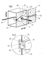
- a channel 10 in the present case of a U-profile which is covered at its open side by a special channel wall in the form of a flexible channel cover 12.
- the channel cover 12 connected at both longitudinal edges with the U-profile of the channel 10 is divided at a central parting line 14 and consists for example of band-shaped rubber or plastic or of a folded material with folds extending in the longitudinal direction L of the channel cover.
- strip-shaped members are arranged, which can be brought into a releasable engagement according to the tongue and groove principle.
- a groove member 16 is formed or attached to the upper portion, while at the lower portion of a hereby engageable spring member 18 is formed or attached.
- peak wedges 28 of the guideways 26 ensure that the tongue and groove members 16, 18 are pulled apart on the input side opening and the output side again closing together.
- outer slots 30 of the feedthrough member 20 allow a free passage of the tongue and groove members 16, 18 connected to the flexible channel cover 12th
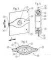
- the existing example of lightweight plastic bushing member 20 may be formed in two parts with a separation in the Q-L plane.
- the guide tracks 26 are freely accessible, so that the tongue and groove members 16, 18 are inserted or removed.
- the guide tracks 26 according to FIG. 1 are closed by a cover element (missing in FIG. 5).
- These two parts of the feedthrough member 20 are releasably held together in its central region, for example by latching or jamming.
Landscapes
- Engineering & Computer Science (AREA)
- Physics & Mathematics (AREA)
- Optics & Photonics (AREA)
- Plasma & Fusion (AREA)
- Mechanical Engineering (AREA)
- Laser Beam Processing (AREA)
Applications Claiming Priority (1)
| Application Number | Priority Date | Filing Date | Title |
|---|---|---|---|
| DE102006047240A DE102006047240A1 (de) | 2006-10-04 | 2006-10-04 | Kanalwand |
Publications (1)
| Publication Number | Publication Date |
|---|---|
| EP1908545A2 true EP1908545A2 (fr) | 2008-04-09 |
Family
ID=38860103
Family Applications (1)
| Application Number | Title | Priority Date | Filing Date |
|---|---|---|---|
| EP20070019307 Withdrawn EP1908545A2 (fr) | 2006-10-04 | 2007-10-02 | Paroi de canal |
Country Status (2)
| Country | Link |
|---|---|
| EP (1) | EP1908545A2 (fr) |
| DE (1) | DE102006047240A1 (fr) |
Families Citing this family (1)
| Publication number | Priority date | Publication date | Assignee | Title |
|---|---|---|---|---|
| DE102013206641B3 (de) | 2013-04-15 | 2014-05-22 | Robert Bosch Gmbh | Verfahren zur Durchführung wenigstens einer Lernfunktion in einem Kraftfahrzeug und Mittel zu dessen Implementierung |
-
2006
- 2006-10-04 DE DE102006047240A patent/DE102006047240A1/de not_active Withdrawn
-
2007
- 2007-10-02 EP EP20070019307 patent/EP1908545A2/fr not_active Withdrawn
Also Published As
| Publication number | Publication date |
|---|---|
| DE102006047240A1 (de) | 2008-04-10 |
Similar Documents
| Publication | Publication Date | Title |
|---|---|---|
| DE102006015799B4 (de) | Abdeckung für Maschinenführungen | |
| EP1153552B1 (fr) | Curseur pour bande de fermeture en matière plastique | |
| DE4418735A1 (de) | Vorrichtung zur Handbetätigung einer Jalousie, vorzugsweise einer Vertikaljalousie | |
| DE19647322A1 (de) | Kettenglied aus verschiedenen Werkstoffen und Verfahren zu dessen Herstellung | |
| DE10256599A1 (de) | Rollosystem, insbesondere für ein Kraftfahrzeug | |
| DE3111871A1 (de) | Elektrischer rasierapparat | |
| DE4230730B4 (de) | Umreifungsmaschine mit einem Bandführungsrahmen | |
| EP1231142A1 (fr) | Outil pour appliquer des liens, notamment à un faisceau de cable | |
| WO2000056606A1 (fr) | Dispositif destine a cercler des paquets et rebords profiles, en particulier destines a couvrir le canal de bande du dispositif de cerclage de paquets | |
| EP1908545A2 (fr) | Paroi de canal | |
| EP0110475A1 (fr) | Appareil radiologique muni d'un support à déplacement longitudinal | |
| DE202011004784U1 (de) | Energieführungskette | |
| EP0084595B1 (fr) | Protecteur pour un organe de machine au moins partiellement découvert | |
| DE4037774C1 (fr) | ||
| DE10109134C2 (de) | Teleskopabdeckung | |
| DE102019220345B3 (de) | Schließeinheit für ein Ablagefach, Ablagefach | |
| EP4320370A1 (fr) | Chaîne porte-câbles à patin de glissement et patin de glissement pouvant être monté ultérieurement prévu à cet effet | |
| DE3924468C2 (fr) | ||
| DE731873C (de) | Staubsaugermundstueck | |
| DE4240725C1 (de) | Biegemaschine für Draht- oder Bandmaterial | |
| EP1334857A1 (fr) | Pare-soleil pour toit de véhicule | |
| DE522664C (de) | Reissverschluss | |
| DE102009043248B3 (de) | Führungsanordnung für ein bewegbares Dachteil eines Fahrzeugdachs | |
| DE4447485A1 (de) | Vorrichtung mit einem Griffkörper zur Handbetätigung einer Vertikaljalousie | |
| DE10123424A1 (de) | Antrieb für ein verstellbares Schließelement eines Fahrzeugdaches |
Legal Events
| Date | Code | Title | Description |
|---|---|---|---|
| PUAI | Public reference made under article 153(3) epc to a published international application that has entered the european phase |
Free format text: ORIGINAL CODE: 0009012 |
|
| AK | Designated contracting states |
Kind code of ref document: A2 Designated state(s): AT BE BG CH CY CZ DE DK EE ES FI FR GB GR HU IE IS IT LI LT LU LV MC MT NL PL PT RO SE SI SK TR |
|
| AX | Request for extension of the european patent |
Extension state: AL BA HR MK RS |
|
| STAA | Information on the status of an ep patent application or granted ep patent |
Free format text: STATUS: THE APPLICATION IS DEEMED TO BE WITHDRAWN |
|
| 18D | Application deemed to be withdrawn |
Effective date: 20110502 |