EP1908545A2 - Duct wall - Google Patents
Duct wall Download PDFInfo
- Publication number
- EP1908545A2 EP1908545A2 EP20070019307 EP07019307A EP1908545A2 EP 1908545 A2 EP1908545 A2 EP 1908545A2 EP 20070019307 EP20070019307 EP 20070019307 EP 07019307 A EP07019307 A EP 07019307A EP 1908545 A2 EP1908545 A2 EP 1908545A2
- Authority
- EP
- European Patent Office
- Prior art keywords
- channel
- groove
- lead
- opening
- laser beam
- Prior art date
- Legal status (The legal status is an assumption and is not a legal conclusion. Google has not performed a legal analysis and makes no representation as to the accuracy of the status listed.)
- Withdrawn
Links
Images
Classifications
-
- B—PERFORMING OPERATIONS; TRANSPORTING
- B23—MACHINE TOOLS; METAL-WORKING NOT OTHERWISE PROVIDED FOR
- B23K—SOLDERING OR UNSOLDERING; WELDING; CLADDING OR PLATING BY SOLDERING OR WELDING; CUTTING BY APPLYING HEAT LOCALLY, e.g. FLAME CUTTING; WORKING BY LASER BEAM
- B23K26/00—Working by laser beam, e.g. welding, cutting or boring
- B23K26/12—Working by laser beam, e.g. welding, cutting or boring in a special environment or atmosphere, e.g. in an enclosure
-
- B—PERFORMING OPERATIONS; TRANSPORTING
- B23—MACHINE TOOLS; METAL-WORKING NOT OTHERWISE PROVIDED FOR
- B23K—SOLDERING OR UNSOLDERING; WELDING; CLADDING OR PLATING BY SOLDERING OR WELDING; CUTTING BY APPLYING HEAT LOCALLY, e.g. FLAME CUTTING; WORKING BY LASER BEAM
- B23K26/00—Working by laser beam, e.g. welding, cutting or boring
- B23K26/12—Working by laser beam, e.g. welding, cutting or boring in a special environment or atmosphere, e.g. in an enclosure
- B23K26/127—Working by laser beam, e.g. welding, cutting or boring in a special environment or atmosphere, e.g. in an enclosure in an enclosure
- B23K26/128—Laser beam path enclosures
Definitions
- the invention relates to a duct wall having a planar duct cover and a passage opening which is movable in the longitudinal direction thereof for passing a medium out of a duct covered by the duct wall, in particular for passing a laser beam of a laser beam processing machine.
- Such channel walls are used, for example, in laser beam processing machines.
- a running in the longitudinal direction of the channel sensitive laser beam which is to be protected from dust and contaminants, laterally led out of the channel via a deflecting mirror connected to a machine slide on the movable passage opening.
- the passage opening is achieved in a known manner with split or juxtaposed normal bellows, Scheibenfaltenbälgen or with a peripheral pinhole band.
- the present invention is therefore the object of a channel wall of the type mentioned in such a way that in a simple and inexpensive overall structure only very small masses are moved and thereby very high operating speeds can be achieved.
- a channel wall of the type mentioned above or in the preamble of claim 1 is characterized by features listed in the characterizing part of claim 1, namely the fact that the Kanalabdekkung of a firmly attached to their longitudinal sides to the channel flexible material consists in that the channel cover has a dividing line between its longitudinal sides, on the adjacent edges of the channel cover by strip-shaped, flexible, interlocking tongue and groove members are releasably connected together, and that on the dividing line in the longitudinal direction thereof reciprocally movable feedthrough member Having passage opening for the medium and is in sliding guide engagement with the tongue and groove members, that these in the direction of movement of the feedthrough member before the passage opening releasing the same wall-opening pulled apart sowi transverse to the direction of movement e behind the same again wall-closing be merged.
- claims 2 to 4 allow a relatively firm cohesion of the two separable portions of the channel cover.
- claims 5 to 7 allow a uniform gentle opening and closing of the channel cover by gradually spreading and merging of the tongue and groove members. This allows a smooth operation even at very high speeds.
- the tongue and groove members may be fixed or releasably held according to claim 10 at the portions of the channel cover. With detachable attachment, they can be replaced as wear parts cost-saving.
- the channel wall can be used excellently in a laser beam processing machine by the feedthrough member and this also connected thereto a deflection mirror is drivingly connected to the machine side.
- a channel 10 in the present case of a U-profile which is covered at its open side by a special channel wall in the form of a flexible channel cover 12.
- the channel cover 12 connected at both longitudinal edges with the U-profile of the channel 10 is divided at a central parting line 14 and consists for example of band-shaped rubber or plastic or of a folded material with folds extending in the longitudinal direction L of the channel cover.
- strip-shaped members are arranged, which can be brought into a releasable engagement according to the tongue and groove principle.
- a groove member 16 is formed or attached to the upper portion, while at the lower portion of a hereby engageable spring member 18 is formed or attached.
- peak wedges 28 of the guideways 26 ensure that the tongue and groove members 16, 18 are pulled apart on the input side opening and the output side again closing together.
- outer slots 30 of the feedthrough member 20 allow a free passage of the tongue and groove members 16, 18 connected to the flexible channel cover 12th
- the existing example of lightweight plastic bushing member 20 may be formed in two parts with a separation in the Q-L plane.
- the guide tracks 26 are freely accessible, so that the tongue and groove members 16, 18 are inserted or removed.
- the guide tracks 26 according to FIG. 1 are closed by a cover element (missing in FIG. 5).
- These two parts of the feedthrough member 20 are releasably held together in its central region, for example by latching or jamming.
Landscapes
- Engineering & Computer Science (AREA)
- Physics & Mathematics (AREA)
- Optics & Photonics (AREA)
- Plasma & Fusion (AREA)
- Mechanical Engineering (AREA)
- Laser Beam Processing (AREA)
Abstract
Description
Die Erfindung betrifft eine Kanalwand mit einer flächigen Kanalabdeckung und einer in deren Längsrichtung beweglichen Durchführungsöffnung zum Durchführen eines Mediums aus einem von der Kanalwand abgedeckten Kanal, insbesondere zum Durchführen eines Laserstrahls einer Laserstrahl-Bearbeitungsmaschine.The invention relates to a duct wall having a planar duct cover and a passage opening which is movable in the longitudinal direction thereof for passing a medium out of a duct covered by the duct wall, in particular for passing a laser beam of a laser beam processing machine.
Derartige Kanalwände kommen beispielsweise bei Laserstrahl-Bearbeitungsmaschinen zum Einsatz. Hierbei wird ein in Längsrichtung des Kanals verlaufender empfindlicher Laserstrahl, der vor Staub und Verunreinigungen zu schützen ist, über einen mit einem Maschinenschlitten verbundenen Umlenkspiegel über die bewegliche Durchführungsöffnung seitlich aus dem Kanal herausgeleitet. Die Durchführungsöffnung wird in bekannter Weise mit geteilten bzw. aneinandergereihten normalen Faltenbälgen, Scheibenfaltenbälgen oder mit einem umlaufenden Lochblendenband erzielt. Diese Mechanismen sind aufwendig und insbesondere auch unter Berücksichtigung der großen Arbeitsgeschwindigkeiten von beispielsweise 300 Metern pro Minute und der relativ großen bewegten Massen träge und anfällig.Such channel walls are used, for example, in laser beam processing machines. In this case, a running in the longitudinal direction of the channel sensitive laser beam, which is to be protected from dust and contaminants, laterally led out of the channel via a deflecting mirror connected to a machine slide on the movable passage opening. The passage opening is achieved in a known manner with split or juxtaposed normal bellows, Scheibenfaltenbälgen or with a peripheral pinhole band. These mechanisms are laborious and, especially considering the high working speeds of, for example, 300 meters per minute and the relatively large moving masses sluggish and prone.
Der vorliegenden Erfindung liegt deshalb die Aufgabe zugrunde, eine Kanalwand der genannten Art so auszubilden, daß bei einfachem sowie preiswertem Gesamtaufbau nur sehr geringe Massen bewegt werden und dadurch sehr große Arbeitsgeschwindigkeiten erzielbar sind.The present invention is therefore the object of a channel wall of the type mentioned in such a way that in a simple and inexpensive overall structure only very small masses are moved and thereby very high operating speeds can be achieved.
Zur Lösung der gestellten Aufgabe zeichnet sich eine Kanalwand der oben bzw. im Oberbegriff von Anspruch 1 genannten Art erfindungsgemäß durch im Kennzeichen von Anspruch 1 aufgeführten Merkmale aus, nämlich dadurch, daß die Kanalabdekkung aus einem an ihren Längsseiten fest mit dem Kanal zu verbindenden flexiblen Material besteht, daß die Kanalabdeckung zwischen ihren Längsseiten eine Trennlinie aufweist, an der einander benachbarte Ränder der Kanalabdeckung durch leistenförmige, biegsame, ineinandergreifende Nut- und Federglieder lösbar miteinander verbunden sind, und daß ein an der Trennlinie in Längsrichtung derselben hin- und hergehend bewegbares Durchführungsglied die Durchführungsöffnung für das Medium aufweist und mit den Nut- und Federgliedern so in gleitendem Führungseingriff steht, daß diese in Bewegungsrichtung des Durchführungsgliedes vor der Durchführungsöffnung unter Freigabe derselben quer zur Bewegungsrichtung wandöffnend auseinandergezogen sowie hinter derselben wieder wandschließend zusammengeführt werden.To achieve the object, a channel wall of the type mentioned above or in the preamble of claim 1 is characterized by features listed in the characterizing part of claim 1, namely the fact that the Kanalabdekkung of a firmly attached to their longitudinal sides to the channel flexible material consists in that the channel cover has a dividing line between its longitudinal sides, on the adjacent edges of the channel cover by strip-shaped, flexible, interlocking tongue and groove members are releasably connected together, and that on the dividing line in the longitudinal direction thereof reciprocally movable feedthrough member Having passage opening for the medium and is in sliding guide engagement with the tongue and groove members, that these in the direction of movement of the feedthrough member before the passage opening releasing the same wall-opening pulled apart sowi transverse to the direction of movement e behind the same again wall-closing be merged.
Dadurch ergibt sich der wesentliche Vorteil, daß die an sich stationäre flexible Kanalwand vom Durchführungsglied stets nur im erforderlichen Umfang bereichsweise geöffnet wird. Somit werden nur die sehr kleinen Massen des Durchführungsgliedes selbst und der jeweils direkt angrenzenden Abschnitte der flexiblen Kanalabdeckung bewegt, so daß sich äußerst große Arbeitsgeschwindigkeiten erzielen lassen. Die Kanalwand läßt sich ferner einfach und preiswert herstellen.This results in the significant advantage that the stationary in itself flexible channel wall by the feedthrough member is always opened only to the extent required in regions. Thus, only the very small masses of the feedthrough member itself and each directly adjacent portions of the flexible channel cover are moved, so that can reach extremely high operating speeds. The channel wall can also be easily and inexpensively manufactured.
Die weiteren Ausgestaltungen der Ansprüche 2 bis 4 ermöglichen einen relativ festen Zusammenhalt der beiden trennbaren Abschnitte der Kanalabdeckung. Dieser relativ feste und dennoch problemfrei lösbare Verschluß kann beispielsweise dann besonders vorteilhaft sein, wenn der Kanal unter einem bestimmten Überdruck mit einem Gas, wie Stickstoff, gespült wird, um diesen schmutzpartikelfrei zu halten.The further embodiments of claims 2 to 4 allow a relatively firm cohesion of the two separable portions of the channel cover. This relatively strong and yet problem-free releasable closure, for example, then special be advantageous if the channel is purged under a certain pressure with a gas such as nitrogen to keep it free of dirt particles.
Die besonders bevorzugten weiteren Merkmale der Ansprüche 5 bis 7 erlauben ein gleichmäßiges schonendes Öffnen und Schließen der Kanalabdeckung durch allmähliches Spreizen und Zusammenführen der Nut- und Federglieder. Das ermöglicht einen ruhigen Betriebsablauf auch bei sehr großen Arbeitsgeschwindigkeiten.The particularly preferred further features of claims 5 to 7 allow a uniform gentle opening and closing of the channel cover by gradually spreading and merging of the tongue and groove members. This allows a smooth operation even at very high speeds.
Durch die Maßnahmen der Ansprüche 8 und 9 ergibt sich ein besonders gewichtsleichtes und einfach manipulierbares Durchführungsglied.The measures of claims 8 and 9 results in a particularly lightweight and easy to manipulate implementing member.
Die Nut- und Federglieder können gemäß Anspruch 10 an den Abschnitten der Kanalabdeckung fest oder lösbar gehalten sein. Bei lösbarer Anbringung können sie als Verschleißglieder kostensparend ausgetauscht werden.The tongue and groove members may be fixed or releasably held according to
Gemäß den Ansprüchen 11 und 12 kann die Kanalwand vorzüglich bei einer Laserstrahl-Bearbeitungsmaschine eingesetzt werden, indem das Durchführungsglied und über dieses auch ein hiermit verbundener Umlenkspiegel antriebsmäßig maschinenseitig angeschlossen wird.According to
Nach Anspruch 13 können für die Kanalabdeckung je nach Einsatzgebiet verschiedene flexible Materialien eingesetzt werden.According to claim 13 different flexible materials can be used for the channel cover depending on the application.
Die Erfindung wird nachfolgend an zeichnerisch dargestellten Ausführungsbeispielen näher erläutert. Es zeigen:
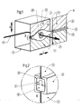
- Fig. 1
- eine in einen Kanal eingebaute Kanalwand nach der vorliegenden Erfindung in einer vereinfachten geschnittenen Perspektive,
- Fig. 2
- ein Detail A aus Fig. 1 in einem vergrößerten Teilschnitt,
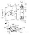
- Fig. 3
- einen Teil der Kanalwand mit einem Durchführungsglied derselben in einer vereinfachten Einzelansicht,
- Fig. 4
- einen vergrößerten Schnitt in einer Schnittansicht A-A aus Fig. 3 und
- Fig. 5
- das geöffnete Durchführungsglied der Kanalwand in einer vergrößerten Schnittansicht B-B aus Fig. 3.
- Fig. 1
- an in-channel duct wall according to the present invention in a simplified sectional perspective,
- Fig. 2
- a detail A of FIG. 1 in an enlarged partial section,
- Fig. 3
- a part of the channel wall with a feedthrough member thereof in a simplified single view,
- Fig. 4
- an enlarged section in a sectional view AA of Fig. 3 and
- Fig. 5
- the opened passage member of the channel wall in an enlarged sectional view BB of Fig. 3rd
Gemäß den Figuren 1 bis 5 besteht ein Kanal 10 im vorliegenden Fall aus einem U-Profil, das an seiner offenen Seite durch eine besondere Kanalwand in Form einer flexiblen Kanalabdeckung 12 abgedeckt ist. Die an beiden Längsrändern mit dem U-Profil des Kanals 10 verbundene Kanalabdeckung 12 ist an einer mittleren Trennlinie 14 geteilt und besteht beispielsweise aus bandförmigem Gummi bzw. Kunststoff oder aber aus einem Faltenmaterial mit in Längsrichtung L der Kanalabdeckung verlaufenden Falten. An den einander benachbarten Rändern der beiden Abschnitte der Kanalabdeckung 12 sind leistenförmige Glieder angeordnet, die nach dem Nut-Feder-Prinzip in einen lösbaren Eingriff gebracht werden können. Im vorliegenden Fall ist am oberen Abschnitt ein Nutglied 16 ausgebildet oder angebracht, während am unteren Abschnitt ein hiermit in Eingriff bringbares Federglied 18 ausgebildet oder angebracht ist.According to the figures 1 to 5, a
Ein in Längsrichtung L hin- und herbewegbares Durchführungsglied 20 mit einer Durchführungsöffnung 22, beispielsweise für einen im Kanal 10 umgelenkten Laserstrahl 24, umgreift und führt die Nut- und Federglieder 16, 18 so, daß diese im Bereich des Durchführungsgliedes hiervon in Querrichtung Q öffnend gespreizt und wieder schließend zusammengeführt werden. Hierzu dienen leicht gekrümmte, randseitige, innere Führungsbahnen 26 des Durchführungsgliedes 20, die die Nut- und Federglieder 16, 18 entsprechend um die Durchführungsöffnung 22 führen. An den Enden des Durchführungsgliedes 20 bzw. sorgen spitze Keile 28 der Führungsbahnen 26 dafür, daß die Nut- und Federglieder 16, 18 eingangsseitig öffnend auseinander gezogen und ausgangsseitig wieder schließend zusammengedrückt werden. In die Führungsbahnen 26 mündende äußere Schlitze 30 des Durchführungsgliedes 20 ermöglichen einen freien Durchgriff der mit den Nut- und Federgliedern 16, 18 verbundenen flexiblen Kanalabdeckung 12.A longitudinally L
Das beispielsweise aus leichtem Kunststoff bestehende Durchführungsglied 20 kann zweiteilig mit einer Trennung in der Q-L Ebene ausgebildet sein. In seinem gemäß Fig. 5 geöffneten Zustand sind die Führungsbahnen 26 frei zugänglich, so daß die Nut- und Federglieder 16, 18 eingelegt oder herausgenommen werden. In seinem geschlossenen Zustand sind die Führungsbahnen 26 gemäß Fig. 1 durch ein Deckelelement (fehlt in Fig. 5) verschlossen. Diese beiden Teile des Durchführungsgliedes 20 werden in dessem zentralen Bereich lösbar zusammengehalten, beispielsweise durch Verrasten oder Verklemmen.The existing example of lightweight
Claims (13)
dadurch gekennzeichnet,
daß die Kanalabdeckung (12) aus einem an ihren Längsseiten fest mit dem Kanal zu verbindenden flexiblen Material besteht,
daß die Kanalabdeckung (12) zwischen ihren Längsseiten eine Trennlinie (14) aufweist, an der einander benachbarte Ränder der Kanalabdeckung durch leistenförmige, biegsame, ineinandergreifende Nut- und Federglieder (16, 18) lösbar miteinander verbunden sind,
und daß ein an der Trennlinie (14) in Längsrichtung (L) derselben hin- und hergehend bewegbares Durchführungsglied (20) die Durchführungsöffnung (22) für das Medium aufweist und mit den Nut- und Federgliedern (16, 18) so in gleitendem Führungseingriff steht, daß diese in Bewegungsrichtung des Durchführungsgliedes vor der Durchführungsöffnung unter Freigabe derselben quer zur Bewegungsrichtung wandöffnend auseinandergezogen sowie hinter derselben wieder wandschließend zusammengeführt werden.Channel wall with a planar channel cover (12) and a longitudinally movable passage opening (22) for passing a medium (24) from a channel wall covered by the channel (10), in particular for carrying out a laser beam of a laser beam processing machine,
characterized,
that the channel cover (12) consists of a fixedly at their longitudinal sides with the channel to be connected to flexible material,
in that the channel cover (12) has a parting line (14) between its longitudinal sides, on which mutually adjacent edges of the channel cover are detachably connected to one another by strip-shaped, flexible, interlocking tongue and groove members (16, 18),
and that at the parting line (14) in the longitudinal direction (L) thereof reciprocally movable feedthrough member (20) the passage opening (22) for the medium and with the tongue and groove members (16, 18) is in sliding guide engagement, that they are pulled apart wall opening in the direction of movement of the feedthrough member before the passage opening releasing the same transverse to the direction of movement and behind the same again wall-closing.
Applications Claiming Priority (1)
| Application Number | Priority Date | Filing Date | Title |
|---|---|---|---|
| DE102006047240A DE102006047240A1 (en) | 2006-10-04 | 2006-10-04 | channel wall |
Publications (1)
| Publication Number | Publication Date |
|---|---|
| EP1908545A2 true EP1908545A2 (en) | 2008-04-09 |
Family
ID=38860103
Family Applications (1)
| Application Number | Title | Priority Date | Filing Date |
|---|---|---|---|
| EP20070019307 Withdrawn EP1908545A2 (en) | 2006-10-04 | 2007-10-02 | Duct wall |
Country Status (2)
| Country | Link |
|---|---|
| EP (1) | EP1908545A2 (en) |
| DE (1) | DE102006047240A1 (en) |
Families Citing this family (1)
| Publication number | Priority date | Publication date | Assignee | Title |
|---|---|---|---|---|
| DE102013206641B3 (en) | 2013-04-15 | 2014-05-22 | Robert Bosch Gmbh | Method for performing learning function used for providing correction value for compensating nominal value of deviation in motor vehicle, involves determining correction values for defined operating state of motor vehicle |
-
2006
- 2006-10-04 DE DE102006047240A patent/DE102006047240A1/en not_active Withdrawn
-
2007
- 2007-10-02 EP EP20070019307 patent/EP1908545A2/en not_active Withdrawn
Also Published As
| Publication number | Publication date |
|---|---|
| DE102006047240A1 (en) | 2008-04-10 |
Similar Documents
| Publication | Publication Date | Title |
|---|---|---|
| DE102006015799B4 (en) | Cover for machine guides | |
| EP1153552B1 (en) | Slider for a plastic fastener tape | |
| DE4418735A1 (en) | Hand operating device for louvres, esp. vertical louvres | |
| DE19647322A1 (en) | Chain link made of different materials and process for its production | |
| DE10256599A1 (en) | Roller blind system, in particular for a motor vehicle | |
| DE3111871A1 (en) | ELECTRIC SHAVER | |
| DE4230730B4 (en) | Strapping machine with a tape guide frame | |
| EP1231142A1 (en) | Binding tool, particularly for cable bundles | |
| WO2000056606A1 (en) | Device for hooping packing units and profile strip, especially for covering the tape channel of a device for hooping packaging units | |
| EP1908545A2 (en) | Duct wall | |
| EP0110475A1 (en) | X-ray apparatus provided with a longitudinally shiftable platform | |
| DE202011004784U1 (en) | Power supply chain | |
| EP0084595B1 (en) | Protective cover for a machine element which is at least partially uncovered | |
| DE4037774C1 (en) | ||
| DE10109134C2 (en) | telescopic cover | |
| DE102019220345B3 (en) | Locking unit for a storage compartment, storage compartment | |
| EP4320370A1 (en) | Energy chain having a skid, and skid retrofittable therefor | |
| DE3924468C2 (en) | ||
| DE731873C (en) | Vacuum cleaner mouthpiece | |
| DE4240725C1 (en) | Wire or strip bending machine - has guide track curving in vertical plane for lockable slide with movable tool=holder | |
| EP1334857A1 (en) | Sunshade for vehicle roof | |
| DE522664C (en) | Zipper | |
| DE102009043248B3 (en) | Guiding arrangement for transparent cover of sunroof in vehicle, has guide rail comprising two guiding channels and channel for guiding drive cable, and sliding element guided in channel and adapted to channel | |
| DE4447485A1 (en) | Cord manual actuator for blind with vertical slats | |
| DE10123424A1 (en) | Drive unit for adjustable closing element of motor vehicle's roof has guide rail on both sides of closing element and with guide element in each guide rail to keep respective operating pull cable away from sides of guide rail |
Legal Events
| Date | Code | Title | Description |
|---|---|---|---|
| PUAI | Public reference made under article 153(3) epc to a published international application that has entered the european phase |
Free format text: ORIGINAL CODE: 0009012 |
|
| AK | Designated contracting states |
Kind code of ref document: A2 Designated state(s): AT BE BG CH CY CZ DE DK EE ES FI FR GB GR HU IE IS IT LI LT LU LV MC MT NL PL PT RO SE SI SK TR |
|
| AX | Request for extension of the european patent |
Extension state: AL BA HR MK RS |
|
| STAA | Information on the status of an ep patent application or granted ep patent |
Free format text: STATUS: THE APPLICATION IS DEEMED TO BE WITHDRAWN |
|
| 18D | Application deemed to be withdrawn |
Effective date: 20110502 |