EP1908438A1 - Vorrichtung zum Umformen von Knochen - Google Patents
Vorrichtung zum Umformen von Knochen Download PDFInfo
- Publication number
- EP1908438A1 EP1908438A1 EP06121632A EP06121632A EP1908438A1 EP 1908438 A1 EP1908438 A1 EP 1908438A1 EP 06121632 A EP06121632 A EP 06121632A EP 06121632 A EP06121632 A EP 06121632A EP 1908438 A1 EP1908438 A1 EP 1908438A1
- Authority
- EP
- European Patent Office
- Prior art keywords
- carrier
- contact surface
- nose
- pressing body
- holding means
- Prior art date
- Legal status (The legal status is an assumption and is not a legal conclusion. Google has not performed a legal analysis and makes no representation as to the accuracy of the status listed.)
- Withdrawn
Links
- 210000000988 bone and bone Anatomy 0.000 title claims description 32
- 238000003825 pressing Methods 0.000 claims abstract description 57
- 238000000465 moulding Methods 0.000 claims abstract description 37
- 238000004519 manufacturing process Methods 0.000 claims abstract description 6
- 210000001331 nose Anatomy 0.000 claims description 54
- 238000007493 shaping process Methods 0.000 claims description 19
- 210000000537 nasal bone Anatomy 0.000 claims description 13
- 230000000284 resting effect Effects 0.000 claims description 2
- 238000000034 method Methods 0.000 abstract description 11
- 230000008569 process Effects 0.000 abstract description 3
- 238000010276 construction Methods 0.000 abstract description 2
- 210000000845 cartilage Anatomy 0.000 description 6
- 210000003128 head Anatomy 0.000 description 6
- 230000008901 benefit Effects 0.000 description 5
- 230000008468 bone growth Effects 0.000 description 3
- 230000001815 facial effect Effects 0.000 description 3
- 230000012010 growth Effects 0.000 description 3
- 238000007634 remodeling Methods 0.000 description 3
- 238000001356 surgical procedure Methods 0.000 description 3
- 239000000969 carrier Substances 0.000 description 2
- 230000008859 change Effects 0.000 description 2
- 238000012937 correction Methods 0.000 description 2
- 238000013499 data model Methods 0.000 description 2
- 230000000694 effects Effects 0.000 description 2
- 239000002184 metal Substances 0.000 description 2
- 238000002435 rhinoplasty Methods 0.000 description 2
- 241000511343 Chondrostoma nasus Species 0.000 description 1
- 241000282412 Homo Species 0.000 description 1
- 230000006978 adaptation Effects 0.000 description 1
- 238000004026 adhesive bonding Methods 0.000 description 1
- 230000003698 anagen phase Effects 0.000 description 1
- 210000003484 anatomy Anatomy 0.000 description 1
- 238000013459 approach Methods 0.000 description 1
- 230000001419 dependent effect Effects 0.000 description 1
- 239000006260 foam Substances 0.000 description 1
- 230000036541 health Effects 0.000 description 1
- 230000002452 interceptive effect Effects 0.000 description 1
- 239000000463 material Substances 0.000 description 1
- 210000000492 nasalseptum Anatomy 0.000 description 1
- 230000001582 osteoblastic effect Effects 0.000 description 1
- 230000001599 osteoclastic effect Effects 0.000 description 1
- 238000012545 processing Methods 0.000 description 1
- 238000005476 soldering Methods 0.000 description 1
- 239000011343 solid material Substances 0.000 description 1
- 230000008719 thickening Effects 0.000 description 1
- 210000000216 zygoma Anatomy 0.000 description 1
Images


Classifications
-
- A—HUMAN NECESSITIES
- A61—MEDICAL OR VETERINARY SCIENCE; HYGIENE
- A61F—FILTERS IMPLANTABLE INTO BLOOD VESSELS; PROSTHESES; DEVICES PROVIDING PATENCY TO, OR PREVENTING COLLAPSING OF, TUBULAR STRUCTURES OF THE BODY, e.g. STENTS; ORTHOPAEDIC, NURSING OR CONTRACEPTIVE DEVICES; FOMENTATION; TREATMENT OR PROTECTION OF EYES OR EARS; BANDAGES, DRESSINGS OR ABSORBENT PADS; FIRST-AID KITS
- A61F5/00—Orthopaedic methods or devices for non-surgical treatment of bones or joints; Nursing devices; Anti-rape devices
- A61F5/01—Orthopaedic devices, e.g. splints, casts or braces
- A61F5/08—Devices for correcting deformities of the nose ; Devices for enlarging the nostril, e.g. for breathing improvement
Definitions
- the invention relates to a device for reshaping of bone or for influencing the bone growth, in particular of the nasal bone.
- the invention further relates to a method for producing a device for reshaping bones.
- the shape of the nose is central to an attractive facial profile. Ideally, the nose is embedded harmoniously in the facial features. However, if the nose has an idiosyncratic shape and / or a disproportionate size, the nose will inevitably become an eye-catcher and thus the dominant part of the face.
- the shape of the nose can today usually be permanently corrected by a relatively small but nevertheless very demanding surgical procedure. In more than 80 percent of the procedures, the nose is reduced in size, in the others the nose is enlarged.
- the nose consists of bony and cartilaginous parts, which form a pyramidal framework under the covering nose skin.
- the nasal septum which is cartilaginous in the anterior part, bony in the posterior part.
- this scaffolding must be designed so that the outer shape of the nose is changed by the covering skin.
- the rhinoplasty can make the nose smaller or larger, correct the shape of the nose and nose with the nostrils and nostrils, and change the length of the nose and the angle between the nose and upper lip.
- the procedure is performed especially for aesthetic reasons to harmonize the nose and the entire face (aesthetic rhinoplasty). So that the procedure leaves no visible traces, the incisions are made in the inside of the nose or at the bridge of the nose.
- the doctor advantageously models the bone and cartilage framework of the nose depending on the objective.
- the nose can be downsized, narrowed or straightened.
- Such correction of the nose should be made only after the completion of bone growth, ie about the age of 16 or 17 years.
- the object of the invention is to provide a device and a method for producing the device, which allows a cost-effective and secure reshaping of bones, and in particular a correction of the nose shape.
- a device for reshaping bones or influencing the growth of bones or cartilage, in particular nasal bones comprising a shaping device with a contact surface intended for resting on the skin, and comprising a holding device which is connectable to the forming device, wherein the holding device and the shaping device are designed cooperatively in such a way that the shaping device can rest on the skin at least on the contact surface while exerting a contact pressure.
- bone is also understood to mean bone-like structures or cartilages.
- a force is exerted on the skin, which is located above the said bone area, which propagates via the skin to the bone, so that the shape of the bone is influenced by the inventive shaping device.
- the device according to the invention is preferably used in children growing up, since the configuration of the bone, in particular of the nasal bone, can be influenced relatively easily in this phase. However, the device according to the invention can also be used for adult humans.
- the device according to the invention is preferably used for several hours per day, for example during sleep.
- the device according to the invention is mounted before going to sleep by placing the shaping device on the nose and fixing the shaping device to the head with a holding device.
- the molding device has contact surfaces, which are aligned, arranged and configured such that during the Sleeping on a predetermined site of the nasal bone a pressing force is exerted.
- the shape of the nasal bone changes, or the growing nasal bone is similar to a predetermined shape.
- This is preferably used during the growth phase, so that the nasal bone has the desired nasal bone shape after completion of bone growth, that is, after the 16th to 17th year of life, and this also retains.
- the inventive device is explained below using the example of the deformation of the nose in detail.
- the device according to the invention is suitable for reshaping almost any human bone, for example also for reshaping the chin or the cheekbones.
- the invention will be described below with reference to exemplary embodiments.
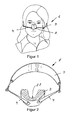
- the device 1 shows a device 1 fixed on the head of a teenager for reshaping nasal bones or for influencing the shape of the nose.
- the device comprises a molding device 2, which is connected via a connecting means 4 with a retaining device 3 running around the head at the rear.
- This device 1 is usually fixed overnight on the head, so that the molding device 2 exerts a pressing force on the skin and the underlying nasal bone during, for example, about eight hours.
- Figure 2 shows the device 1 shown in Figure 1 in detail.
- the shaping device 2 is shown in a cross section, so that the recess 21 for receiving the nose can be seen.
- the molding device 2 is designed in one piece and thus consists of a single part.
- the holding device 3 is preferably elastic and the connecting means 4 are preferably designed to be rigid so that the forming device 2 is pressed against the nose with a sufficiently large force and remains slip-resistant, in particular during sleep.
- the holding device 3 can be configured in various ways to be attached to the head. For example, the holding device 3 also two or have three behind the head extending bands to effect a better grip.
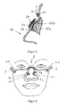
- FIG. 3 shows a longitudinal section through the molding apparatus 2 illustrated in FIG. 2.
- the course of the nose 17 is shown only schematically and by dashed lines.
- the nose has a bump 17b.
- the molding device 2 has at least one support surface 2b with a contact surface 2d that is intended to rest on the skin, so that the contact pressure exerted by the molding device 2 preferably takes place largely over the contact surface 2d.
- the bearing surface 2b is therefore designed with respect to orientation and / or size and / or surface profile such that the force generated via the contact surface 2d acts on a specific skin site and thus on a predetermined bone area 17b to influence its shape and / or growth.
- the contact surface 2d can be arranged and configured in various ways, and for example also consist of two or more partial surfaces, or for example along the entire length of the nose saddle or along the side contours.
- the arrangement, number, size and orientation of the contact surfaces 2d is determined by the position of the bone or cartilage regions whose shape and / or growth should be influenced. Therefore, it is also important that the forming device 2 can be reproducibly the same or similar arranged placed on the nose during preferably a larger number of applications, so that the pressing force is exerted on the same bone areas. Therefore, it may prove advantageous to provide the molding device 2 with a recess 21 configured in such a way that the molding device 2 can be placed on the nose virtually centering itself.
- the shaping device 2 is made, for example Made of plastic, wherein the molding device 2 may also have locally different elasticities.
- the shaping device 2 comprises a carrier 2a with an anatomically configured support surface 2b, the carrier 2a being connected to the connection means 4.
- the carrier 2a consists for example of a metallic frame 2m and an elastic plastic 2n, which forms the support surface 2b.
- the course of the inner contour of the carrier 2a corresponds to the course of the outer contour of the root of the nose, so that the carrier 2a can be applied to the face so that the carrier 2a surrounds the noses and rests on the nose over the support surface 2b on the face.
- This extensive and determined by the position of the nose application of the carrier 2a has the advantage that the carrier 2a reproducibly the same and slip resistant or substantially slip resistant, similar as shown in Figure 1, can be created.
- the carrier 2a or its metal frame 2m thus forms a base part to which one or more pressing bodies 2c can be fastened.
- a pressing body 2c is firmly connected to the carrier 2a via two holding means 2e formed as webs.
- the pressing body 2c has a contact surface 2d. It could also be several Anpress stresses 2c connected to the carrier 2a.
- the pressing bodies 2c could also be connected to the carrier 2a only with a single holding means 2e.
- the pressing bodies 2c could also be arranged to be displaceable and / or detachable and fixable with respect to the holding means 2e.
- the carrier 2a shown in FIG. 4 can thus be fitted in 2 different ways with Anpress emotionsn 2c.
- FIG. 5 schematically shows a longitudinal section through a nose 17 with a nasal bone 17a.
- the molding device 2 shown in Figure 4 is placed on the nose 17, the molding device 2 shown in Figure 4 is placed.
- the pressing body 2c with contact surface 2d bears against the nasal protuberance 17b, and exerts a contact force acting on the nasal protuberance 17b or on the nasal bone 17a.
- the pressing body 2c or the contact surface 2d can, as already described with FIG. 3, be designed and arranged in a large number of ways, depending on the respective anatomical shape of the nose. It is also possible to provide a plurality of contact surfaces 2d or even a plurality of contact bodies 2c.
- FIG. 6 schematically shows a forming device 2 with a carrier 2a, on which two pressing bodies 2c are arranged, each pressing body 2c being fixedly connected to the carrier 2a via a holding means 2e.
- the pressing bodies 2c are detachably connected to the respective holding means 2e, so that the pressing bodies 2c can be exchanged.
- the carrier 2a is connected to the holding device 3 with rigid connecting means 4 or via a face bow 5.
- FIG. 7 shows a further embodiment of a forming device 2 with carrier 2a and two pressing bodies 2c.
- a U-shaped designed holding means 2e is connected at both ends to the carrier 2a, wherein a pressing body 2c is attached to the U-shaped holding means 2e.
- the holding means 2e is over a as a face bow. 5 designed connecting means 4 connected to the holding device 3.
- the entire shaping device 2 is thus connected to the holding device 3 via the face bow 5.
- Face bow 5 is understood to mean a rigid, curved wire which transfers the force from the shaping device 2 to the holding device 3.
- the face bow 5 is preferably designed to be curved or arched so that it does not bear against the skin, and thus connect the shaping device 2 to the holding device 3 without touching the skin.
- the shaping device 2 could be connected to the holding device 3 simultaneously both via the connecting means 4 shown in FIG. 6 and via the face bow 5 shown in FIG.
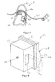
- FIG. 8 shows an embodiment of a pressing body 2c in detail.
- the pressing body 2c comprises a base part 2f with a recess 2g, wherein, as indicated by dashed lines, a carrier 2a or a holding means 2e extends through the recess 2g so that the pressing body 2c is slidably mounted with respect to the carrier 2a or the holding means 2e, and with a Screw 2h can be fixed.
- the pressing body 2c comprises a base plate 2i on which a molded part 2k is arranged.
- the molded part 2k has on the side opposite the base plate 2i a surface 21, which is preferably designed to extend three-dimensionally, wherein the surface 21 forms at least one defined contact surface 2d, which is indicated in Figure 8.
- the molded part 2k is preferably made of a skin-friendly material, for example a plastic.
- an Anpress stresses 2c has the advantage that the course of the surface 21 can be configured individually, whereas the other parts of the Anpress stressess 2c may be formed as identically designed standard parts.
- Each pressing body 2c is preferably provided with a mold part 2k which extends in accordance with the individual requirements or with an individually extending surface 21.
- FIG. 9 shows in detail how the contact bodies 2c shown in FIG. 8 could be fastened to a holding means 2e, for example the forming device 2 shown in FIG.
- FIG. 9 schematically shows a holding means 2e to which the two pressing bodies 2c are firmly fixed by means of screws 2h.
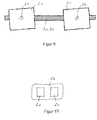
- FIG. 10 schematically shows a further molded part 2k which, in contrast to the exemplary embodiment shown in FIG. 8, is connected to two pressing bodies 2c.
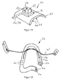
- FIG. 11 shows a further embodiment of a pressing body 2c.
- the pressing body 2c comprises a base part 2f with a recess 2g into which a holding means 2e protrudes.
- the holding means 2e is detachably connected to the base part 2f by means of the screw 2h.
- the pressing body 2c also comprises a molded part 2k, which is connected to the base part 2f via the base plate 2i.
- the molded part 2k has a surface 21 which forms a contact surface 2d.
- FIG. 12 shows a further exemplary embodiment of a carrier 2a with a round, metallic frame or a plastic frame 2m as well as an elastic plastic 2n enclosing the frame 2m.
- the metallic frame or the plastic frame 2m may be designed as flexible in an advantageous embodiment, so that the course of the frame 2m, for example, the anatomical profile of the nose or the root of the nose can be adjusted accordingly.
- Each leg of the carrier 2a is connected via a respective face bow 5 with the holding device 3.
- the two facial arches 5 are firmly connected to each other at the intersection.
- FIG. 13 shows in a detailed view how a holding means 2e or a face bow 5 can be connected to the carrier 2a.
- the carrier 2a has in the plastic 2n a hole 2o, which open into an internal thread 2p of the frame 2m.
- the holding means 2e or the face bow 5 has an external thread, which is screwed firmly to the internal thread 2p, so that the holding means 2e is firmly and detachably connected to the carrier 2a.
- the connection of frame 2m and holding means 2e could also be done via a plug or snap connection.
- the carrier 2a may have a plurality of such holes 2o, via which a pressing body 2c, for example the pressing body 2c shown in FIG. 11, can be connected to the carrier 2a. As shown in FIG.
- this plurality of holes 20 has the advantage that the pressing body 2c can be fastened in a large number of possible positions with respect to the carrier 2a or with respect to the nose 17. It is also possible to connect a plurality of AnpressMechn 2c firmly with a carrier 2a. In preferably opposite holes 2o, for example, as shown in Figure 7, a u-shaped holding means 2e can be anchored. It could also be a plurality in the longitudinal direction of the nose spaced holding means 2e connected to the carrier 2a.
- a kit or a kit when adapting the molding device 2, which has a plurality of carriers 2a of different size and / or shape, and a plurality of pressing bodies 2c, preferably also of different size and / or shape, and a plurality different face bow 5 includes.
- a kit makes it possible to form a plurality of differently designed, individually adapted to the anatomy of a human form devices 2.
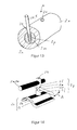
- FIG. 14 shows a further exemplary embodiment of a pressing body 2c, which is connected via a holding means 2p to a carrier 2a or a holding means 2e.
- the pressing body 2c comprises a preformed base plate 2i of preferably solid material such as metal or plastic, as well as a soft molded part 2k, for example of foam.
- the holding means 2p comprises two base parts 2f, the one base part 2f being fixedly and detachably connected to the carrier 2a or the holding means 2e by means of the screw 2h. After loosening the screw 2h, the base part 2f can be displaced along the carrier 2a or the holding means 2e.
- the base part 2f arranged at the bottom in FIG. 14 is firmly connected to the base plate 2i.
- the two base parts 2f have oppositely extending internal threads, in which a distance setting thread 2o is rotatably mounted, so that the distance between the two base parts 2f by turning the distance adjustment thread 20 can be increased or reduced.
- a key 2m may be inserted into a hole of the distance adjusting thread 2o and then rotated in the direction of movement A to thereby enlarge or reduce the overall length of the holding means 2p, thereby to act on the nose To increase or decrease the contact force.
- the key 2m is preferably inserted only for adjusting the holding means 2p in the distance adjusting thread 2o, and then completely removed.
- a plurality of holding means 2e which are detachably or fixedly connected to the carrier 2a, may also be arranged on the carrier 2a.
- the holding means 2e can also be configured in the form of a lattice, with, for example, firmly connected crossing points.
- the holding means 2e are advantageously configured as a thin wire of, for example, 1 mm, or 0.5 mm to 1.5 mm in diameter, wherein the grid is curved in such a way that, when the forming device 2 is attached, it extends at a distance from the nose.
- Such a carrier 2a with holding means 2e may have a very low weight.
- a Anpress redesign 2c used which has intersecting grooves 2n.
- This Pressing body 2c as shown in FIG. 16, is advantageously connected to them at intersecting holding means 2e, eg by soldering or gluing, so that the pressing body 2c is held in a precisely defined position in the grid or in the forming device 2.
- the contact body 2c can also be replaced by another contact body 2c.
- FIG. 17 shows a cross section through a further exemplary embodiment of a pressing body 2c.
- the Anpress stresses 2c according to Figure 17 in addition to a molded part 2k, which forms the contact surface 2d.
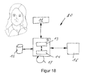
- FIG. 18 schematically shows a device 10 for producing the molding device 2.
- the creation of a molding device 2 for shaping the nose is shown.
- the same device 10 is also suitable for creating molding devices 2 for other body parts.
- the shape of the nose is scanned with a 3-dimensional scanner 11 and the data is transmitted to a server 12.
- a 3-dimensional data model of the measured shape of the nose is stored.
- the server has access to a database 15 in which the data of a plurality of forming devices 2, carriers 2a, pressing bodies 2c, etc. are stored.
- the processing module 13 stored in the server 12 is capable of, based on To propose the construction of a suitable shaping device 2 to the named, available data.
- the entire molding apparatus 2 may be assembled based on standard components, for example.
- the surface profile of the molded part 2k of each pressing body 2c is configured individually, for example, by connecting the server 12 to a machine 16, which allows to produce a molded part 2k with an individually extending surface 21.
- the pressing bodies 2c are provided in their basic form with a constantly thick molded part 2k. This molded part 2k can be processed individually in the machine 16, so that the molded part 2k produced in this way has an individually extending surface 21, with at least one contact surface 2d.
- the at least one pressing body 2c is then attached to the carrier 2a, so that the forming device 2 is formed, which can then be applied with a biasing force to the nose to influence the shape thereof.
Landscapes
- Health & Medical Sciences (AREA)
- Otolaryngology (AREA)
- Pulmonology (AREA)
- Nursing (AREA)
- Orthopedic Medicine & Surgery (AREA)
- Engineering & Computer Science (AREA)
- Biomedical Technology (AREA)
- Heart & Thoracic Surgery (AREA)
- Vascular Medicine (AREA)
- Life Sciences & Earth Sciences (AREA)
- Animal Behavior & Ethology (AREA)
- General Health & Medical Sciences (AREA)
- Public Health (AREA)
- Veterinary Medicine (AREA)
- Orthopedics, Nursing, And Contraception (AREA)
- Transplanting Machines (AREA)
- Blow-Moulding Or Thermoforming Of Plastics Or The Like (AREA)
Priority Applications (9)
| Application Number | Priority Date | Filing Date | Title |
|---|---|---|---|
| EP06121632A EP1908438A1 (de) | 2006-10-02 | 2006-10-02 | Vorrichtung zum Umformen von Knochen |
| BRPI0719958-9A2A BRPI0719958A2 (pt) | 2006-10-02 | 2007-10-01 | Dispositivo para a remodelagem de ossos |
| PCT/EP2007/060403 WO2008040708A2 (de) | 2006-10-02 | 2007-10-01 | Vorrichtung zum umformen von knochen |
| PCT/EP2007/060402 WO2008040707A2 (de) | 2006-10-02 | 2007-10-01 | Vorrichtung zum umformen von knochen |
| US12/311,582 US20100042139A1 (en) | 2006-10-02 | 2007-10-01 | Device for reshaping bones |
| EP07820785A EP2068787B1 (de) | 2006-10-02 | 2007-10-01 | Vorrichtung zum umformen von knochen |
| ES07820785T ES2379894T3 (es) | 2006-10-02 | 2007-10-01 | Dispositivo para remodelar huesos |
| AT07820785T ATE539717T1 (de) | 2006-10-02 | 2007-10-01 | Vorrichtung zum umformen von knochen |
| MA31828A MA30861B1 (fr) | 2006-10-02 | 2009-04-28 | Dispositif pour deformer des os |
Applications Claiming Priority (1)
| Application Number | Priority Date | Filing Date | Title |
|---|---|---|---|
| EP06121632A EP1908438A1 (de) | 2006-10-02 | 2006-10-02 | Vorrichtung zum Umformen von Knochen |
Publications (1)
| Publication Number | Publication Date |
|---|---|
| EP1908438A1 true EP1908438A1 (de) | 2008-04-09 |
Family
ID=37775194
Family Applications (2)
| Application Number | Title | Priority Date | Filing Date |
|---|---|---|---|
| EP06121632A Withdrawn EP1908438A1 (de) | 2006-10-02 | 2006-10-02 | Vorrichtung zum Umformen von Knochen |
| EP07820785A Not-in-force EP2068787B1 (de) | 2006-10-02 | 2007-10-01 | Vorrichtung zum umformen von knochen |
Family Applications After (1)
| Application Number | Title | Priority Date | Filing Date |
|---|---|---|---|
| EP07820785A Not-in-force EP2068787B1 (de) | 2006-10-02 | 2007-10-01 | Vorrichtung zum umformen von knochen |
Country Status (7)
| Country | Link |
|---|---|
| US (1) | US20100042139A1 (es) |
| EP (2) | EP1908438A1 (es) |
| AT (1) | ATE539717T1 (es) |
| BR (1) | BRPI0719958A2 (es) |
| ES (1) | ES2379894T3 (es) |
| MA (1) | MA30861B1 (es) |
| WO (2) | WO2008040708A2 (es) |
Cited By (2)
| Publication number | Priority date | Publication date | Assignee | Title |
|---|---|---|---|---|
| CN106726079A (zh) * | 2017-02-07 | 2017-05-31 | 济南市第三人民医院 | 一种可调式外鼻偏斜矫正装置 |
| FR3047410A1 (fr) * | 2016-02-09 | 2017-08-11 | S E L A R L De Medecins Plasticiens Paris | Ensemble d'instruments de modelage du nez, procede de realisation et procede de modelage du nez |
Families Citing this family (9)
| Publication number | Priority date | Publication date | Assignee | Title |
|---|---|---|---|---|
| US8801751B2 (en) * | 2012-10-26 | 2014-08-12 | Heal Medical Llc | Nasal splint |
| WO2016187465A1 (en) * | 2015-05-20 | 2016-11-24 | Kurzban Scott | Facial alignment system |
| FR3080025B1 (fr) | 2018-04-17 | 2023-04-21 | Bone 3D | Attelle de nez et procede de fabrication d’une attelle de nez |
| US20210085509A1 (en) * | 2019-09-20 | 2021-03-25 | R. Joseph Magness | Nasal device for improving nasal breathing |
| CN110840641B (zh) * | 2019-12-02 | 2021-10-08 | 首都医科大学附属北京口腔医院 | 个体化鼻基底塑形器及其制作方法 |
| CN111603292B (zh) * | 2020-05-19 | 2023-04-28 | 河南大学 | 一种儿童鼻中隔偏曲矫正器 |
| US11484430B2 (en) | 2020-10-06 | 2022-11-01 | Paul E. Chasan MD Inc. | Compressive nasal device and method for using the same |
| CN112641489A (zh) * | 2020-12-31 | 2021-04-13 | 华中科技大学 | 用于鼻中隔矫正术的鼻腔填充气囊及其制造方法和系统 |
| US11690751B2 (en) | 2021-01-25 | 2023-07-04 | Marcelo Ghersi | Adjustable nasal molding splint |
Citations (5)
| Publication number | Priority date | Publication date | Assignee | Title |
|---|---|---|---|---|
| DE76055C (de) * | H. WEIDLER in Stauchitz, Sachsen | Geraderichter für schiefe Nasen | ||
| DE321737C (de) * | 1919-04-13 | 1920-06-12 | Max Baginski | Aus einer Umhuellungskappe und einem von dieser umschlossenen, einstellbaren Druckteil bestehender Nasenformer |
| DE811255C (de) * | 1949-07-17 | 1951-08-20 | Wilhelm Wesche | Geraet zum AEndern von Nasenformen |
| DE1104655B (de) * | 1954-04-15 | 1961-04-13 | Gustave Aufricht | Nasenformer |
| US3742943A (en) * | 1972-01-03 | 1973-07-03 | O Malmin | Rhinoplasty treatment, method, and apparatus |
Family Cites Families (56)
| Publication number | Priority date | Publication date | Assignee | Title |
|---|---|---|---|---|
| US1100991A (en) * | 1914-01-28 | 1914-06-23 | Anna D Rostow | Device for shaping noses. |
| US1372089A (en) * | 1920-02-21 | 1921-03-22 | Anna D Rostow | Nose-shaper and surgical supporter |
| US1378455A (en) * | 1920-08-04 | 1921-05-17 | Hilgers John | Nose-shaper |
| US1436313A (en) * | 1921-10-12 | 1922-11-21 | George E Hafer | Nose protector |
| US1487628A (en) * | 1922-07-28 | 1924-03-18 | Hofe Frederick Herbert Von | Bandage |
| US1950839A (en) * | 1933-01-06 | 1934-03-13 | Chirila Doonisie Daniel | Nostril dilator |
| US2024491A (en) * | 1935-01-10 | 1935-12-17 | Veysey Helen Beatrice | Surgical bandage |
| US2161607A (en) * | 1938-02-09 | 1939-06-06 | Elmer W Anderson | Nasal filter device |
| US2241292A (en) * | 1939-05-13 | 1941-05-06 | Anthony A Burke | Swimming appliance |
| US2245969A (en) * | 1939-11-27 | 1941-06-17 | Francisco Charles Henry | Nasal inhaler |
| US2318790A (en) * | 1941-09-08 | 1943-05-11 | Martindale Electric Company | Respirator |
| US2319837A (en) * | 1942-12-09 | 1943-05-25 | David R Womack | Adjustable nose splint |
| US2398073A (en) * | 1945-04-07 | 1946-04-09 | Joseph G Bonde | Adjustable nose splint |
| US3426751A (en) * | 1967-01-03 | 1969-02-11 | Milton G Radewan | Post-operative nose stent |
| US3594813A (en) * | 1968-07-10 | 1971-07-27 | Roger S Sanderson | Protective device |
| US4213452A (en) * | 1979-05-03 | 1980-07-22 | The Denver Splint Company | Compound splint and kit |
| US4340040A (en) * | 1981-01-02 | 1982-07-20 | Straith Richard E | Nose splint |
| US4534342A (en) * | 1984-03-28 | 1985-08-13 | Charles Pexa | Nose bandage |
| US5362303A (en) * | 1991-11-08 | 1994-11-08 | Dale Medical Products, Inc. | Nasal dressing holder |
| AT403003B (de) * | 1996-01-24 | 1997-10-27 | Raunig Hermann Dr | Verbundmaterial-nasenschiene |
| US5752511A (en) * | 1996-11-22 | 1998-05-19 | Simmons; Carl J. | Universal medical tube retainer and nasal wall tissue dilator |
| US6106541A (en) * | 1997-05-16 | 2000-08-22 | Hurbis; Charles G. | Surgically implantable nasal dilator |
| US6039710A (en) * | 1997-09-29 | 2000-03-21 | Twentieth Century Fox Film Corporation | Apparatus for providing facial support |
| US6116236A (en) * | 1997-11-12 | 2000-09-12 | Wyss; Gerard J. | Respirator |
| US5947123A (en) * | 1998-03-06 | 1999-09-07 | Shippert; Ronald D. | Nose splint with contoured nose contacting surface |
| US6196223B1 (en) * | 1998-04-10 | 2001-03-06 | William A. Belfer | Strapless respiratory facial mask for customizing to the wearer's face |
| DE19917287A1 (de) * | 1999-04-16 | 2000-11-02 | Storz Karl Gmbh & Co Kg | Medizinisches Instrument für die Nasenplastik |
| US6336456B1 (en) * | 1999-05-21 | 2002-01-08 | Philip H. Ruben | Surgical mask with nasal dilator |
| US6375667B1 (en) * | 1999-09-23 | 2002-04-23 | North American Financial Corp | Nasal dilator |
| US6669712B1 (en) * | 2000-06-30 | 2003-12-30 | Norman Cardoso | Nasal oxygen cannula with supply tube management |
| KR100797727B1 (ko) * | 2000-10-03 | 2008-01-23 | 마사키 니시오카 | 콧날 교정구 |
| US6837238B2 (en) * | 2001-10-12 | 2005-01-04 | Southmedic Incorporated | Lightweight oxygen delivery device for patients |
| US7156097B2 (en) * | 2001-11-27 | 2007-01-02 | Norman Cardoso | Nasal cannula |
| US6532598B1 (en) * | 2002-02-07 | 2003-03-18 | Venanzio Cardarelli | Patient mask |
| US8012163B2 (en) * | 2002-02-15 | 2011-09-06 | Medtronic, Inc. | Occluding and stabilizing medical device |
| US7000611B2 (en) * | 2002-03-26 | 2006-02-21 | Klemperer Walter G | Mouthpiece, nasal seal, head appliance, apparatus, and methods of treating sleep apnea |
| US6758215B2 (en) * | 2002-10-17 | 2004-07-06 | Paul G. Begum | Aromatic travel mask |
| KR200316234Y1 (ko) * | 2003-03-03 | 2003-06-12 | 박성용 | 건강성유지를 이용한 마스크 |
| US7328705B2 (en) * | 2003-03-10 | 2008-02-12 | Mark Abramson | Dental appliance for improving airflow through nasal-pharyngeal airway |
| US7048761B2 (en) * | 2003-03-18 | 2006-05-23 | Farideh Salehi Ajili | Breast augmentation apparatus and method of use |
| US7284730B2 (en) * | 2003-04-09 | 2007-10-23 | Dale Medical Products, Inc. | Transducer holder |
| TWI257872B (en) * | 2003-04-28 | 2006-07-11 | Wisepoint Technology Co Ltd | Nose mask |
| US7117543B1 (en) * | 2003-10-14 | 2006-10-10 | Angel Gunnarshaug | Nose protection shield |
| WO2005082301A1 (en) * | 2004-02-23 | 2005-09-09 | Aqueduct Medical, Inc. | Temperature-controllable device |
| US7802572B2 (en) * | 2004-09-20 | 2010-09-28 | Sutter West Bay Hospitals | Face mask |
| US7624735B2 (en) * | 2004-09-21 | 2009-12-01 | Respironics Respiratory Drug Delivery (Uk) Ltd | Cheek-mounted patient interface |
| US7861317B2 (en) * | 2004-10-08 | 2011-01-04 | Robert Beliveau | Nose cover |
| US7055523B1 (en) * | 2005-02-24 | 2006-06-06 | Brown Thomas W | Internal nasal dilator and delivery mechanism |
| US7287528B2 (en) * | 2005-04-13 | 2007-10-30 | Ric Investments, Llc | Cushion inside a cushion patient interface |
| US8161971B2 (en) * | 2006-08-04 | 2012-04-24 | Ric Investments, Llc | Nasal and oral patient interface |
| US20080082030A1 (en) * | 2006-09-08 | 2008-04-03 | Steven Mark Clark | Adjustable nose splint |
| US7726314B1 (en) * | 2006-12-06 | 2010-06-01 | Christopher Koo Khim Ming | Nebulizer, filter or inhalant mask encouraging use thereof |
| US20080271739A1 (en) * | 2007-05-03 | 2008-11-06 | 3M Innovative Properties Company | Maintenance-free respirator that has concave portions on opposing sides of mask top section |
| CN105126222A (zh) * | 2008-06-04 | 2015-12-09 | 瑞思迈有限公司 | 患者接口系统 |
| USD592358S1 (en) * | 2008-06-05 | 2009-05-12 | Yaroslav Masliantchouk | Nose protector |
| US8074660B2 (en) * | 2008-12-18 | 2011-12-13 | 3M Innovative Properties Company | Expandable face mask with engageable stiffening element |
-
2006
- 2006-10-02 EP EP06121632A patent/EP1908438A1/de not_active Withdrawn
-
2007
- 2007-10-01 EP EP07820785A patent/EP2068787B1/de not_active Not-in-force
- 2007-10-01 WO PCT/EP2007/060403 patent/WO2008040708A2/de active Application Filing
- 2007-10-01 US US12/311,582 patent/US20100042139A1/en not_active Abandoned
- 2007-10-01 ES ES07820785T patent/ES2379894T3/es active Active
- 2007-10-01 AT AT07820785T patent/ATE539717T1/de active
- 2007-10-01 BR BRPI0719958-9A2A patent/BRPI0719958A2/pt not_active IP Right Cessation
- 2007-10-01 WO PCT/EP2007/060402 patent/WO2008040707A2/de active Application Filing
-
2009
- 2009-04-28 MA MA31828A patent/MA30861B1/fr unknown
Patent Citations (5)
| Publication number | Priority date | Publication date | Assignee | Title |
|---|---|---|---|---|
| DE76055C (de) * | H. WEIDLER in Stauchitz, Sachsen | Geraderichter für schiefe Nasen | ||
| DE321737C (de) * | 1919-04-13 | 1920-06-12 | Max Baginski | Aus einer Umhuellungskappe und einem von dieser umschlossenen, einstellbaren Druckteil bestehender Nasenformer |
| DE811255C (de) * | 1949-07-17 | 1951-08-20 | Wilhelm Wesche | Geraet zum AEndern von Nasenformen |
| DE1104655B (de) * | 1954-04-15 | 1961-04-13 | Gustave Aufricht | Nasenformer |
| US3742943A (en) * | 1972-01-03 | 1973-07-03 | O Malmin | Rhinoplasty treatment, method, and apparatus |
Cited By (4)
| Publication number | Priority date | Publication date | Assignee | Title |
|---|---|---|---|---|
| FR3047410A1 (fr) * | 2016-02-09 | 2017-08-11 | S E L A R L De Medecins Plasticiens Paris | Ensemble d'instruments de modelage du nez, procede de realisation et procede de modelage du nez |
| WO2017137356A1 (fr) * | 2016-02-09 | 2017-08-17 | S.E.L.A.R.L De Medecins Plasticiens Paris | Ensemble d'instruments de modelage du nez, procede de realisation et procede de modelage du nez |
| CN108778196A (zh) * | 2016-02-09 | 2018-11-09 | 法国医疗整形公司 | 一组鼻子塑造器具、制造方法和塑造鼻子的方法 |
| CN106726079A (zh) * | 2017-02-07 | 2017-05-31 | 济南市第三人民医院 | 一种可调式外鼻偏斜矫正装置 |
Also Published As
| Publication number | Publication date |
|---|---|
| ATE539717T1 (de) | 2012-01-15 |
| WO2008040708A2 (de) | 2008-04-10 |
| EP2068787B1 (de) | 2012-01-04 |
| WO2008040708A3 (de) | 2008-06-05 |
| WO2008040707A2 (de) | 2008-04-10 |
| ES2379894T3 (es) | 2012-05-04 |
| WO2008040707A3 (de) | 2008-06-05 |
| EP2068787A2 (de) | 2009-06-17 |
| BRPI0719958A2 (pt) | 2014-04-29 |
| MA30861B1 (fr) | 2009-11-02 |
| US20100042139A1 (en) | 2010-02-18 |
Similar Documents
| Publication | Publication Date | Title |
|---|---|---|
| EP1908438A1 (de) | Vorrichtung zum Umformen von Knochen | |
| EP2001381B1 (de) | Verfahren und vorrichtung zur herstellung eines entsprechend einer anatomischen sollform vorgeformten flächigen implantats für einen menschlichen oder tierischen körper | |
| DE69738301T2 (de) | Wirbelsäulendistraktionsimplantat | |
| DE69633302T2 (de) | Regelbare positionierungsanlage für knochen | |
| DE60209732T2 (de) | System zur osteosynthese an der wirbelsäule und verfahren zu dessen herstellung | |
| DE69725567T2 (de) | Haltetransplantat | |
| DE4432891C2 (de) | Vorrichtung und Maskenteilesatz zur nicht invasiven stereotaktischen Immobilisation in reproduzierbarer Position | |
| DE69838851T2 (de) | Wirbelsäulendistraktionsimplantat | |
| EP0039323B1 (de) | Schiene zur Reposition und Ruhigstellung von Finger- und Mittelhandfrakturen, sowie Verfahren zur Herstellung derselben | |
| EP3033019B1 (de) | Praeformiertes implantat zur reposition und fixation einer zentrolateralen mittelgesichtsfraktur | |
| DE3839859A1 (de) | Knochenplatte | |
| EP2030596A1 (de) | Implantat zur Behandlung von Knochen, Verfahren zum Konstruieren der Form eines Implantats und Stützstruktur für ein Implantat | |
| DE102015107484A1 (de) | Orthogonatisches Säge- und Positionierungsimplantat | |
| EP1562529A1 (de) | Kopfstütze für patientenlagerfläche | |
| WO2015157784A1 (de) | Zahnimplantatsystem | |
| DE102008051532B4 (de) | Verfahren zur präoperativen Anpassung eines zur Fixierung der Bruchfragmente eines Knochens dienenden Implantats an die Außenkontur des Knochens | |
| DE2946784A1 (de) | Vorrichtung zum festlegen von gebrochenen knochen | |
| EP3616636B1 (de) | Knochenplatte und chirurgische sets | |
| EP0443388B1 (de) | Fixations- und Mobilisationsschiene | |
| EP3834778A1 (de) | Implantat zur behandlung von knochen | |
| DE202016101200U1 (de) | Steuerungsstruktur für die Positionierung kieferorthopädischer Brackets | |
| DE102019002200A1 (de) | Externe Kopfapparatur zur Senkung des Tonus der Kaumuskulatur bei Patienten mit Bruxismus und/oder anderen craniomandibulären Dysfunktionen (CMD) | |
| DE202019001429U1 (de) | Externe Kopfapparatur zur Senkung des Tonus der Kaumuskulatur bei Patienten mit Bruxismus und/oder anderen craniomandibulären Dysfunktionen (CMD) | |
| DE102021125144A1 (de) | Verbesserte externe Kopfapparatur zur Senkung des Tonus der Kaumuskulatur bei Patienten mit Bruxismus und/oder anderen craniomandibulären Dysfunktionen (CMD) | |
| Voigt | Mous, Maarten: Alagwa–A South Cushitic Language of Tanzania. Grammar, Texts and Lexicon. Köln: Rüdiger Köppe 2016. xvii, 354 S. 8°. Cushitic and Omotic Studies, 7.€ 79, 80. ISBN 978-3-89645-492-8 |
Legal Events
| Date | Code | Title | Description |
|---|---|---|---|
| PUAI | Public reference made under article 153(3) epc to a published international application that has entered the european phase |
Free format text: ORIGINAL CODE: 0009012 |
|
| AK | Designated contracting states |
Kind code of ref document: A1 Designated state(s): AT BE BG CH CY CZ DE DK EE ES FI FR GB GR HU IE IS IT LI LT LU LV MC NL PL PT RO SE SI SK TR |
|
| AX | Request for extension of the european patent |
Extension state: AL BA HR MK RS |
|
| AKX | Designation fees paid | ||
| REG | Reference to a national code |
Ref country code: DE Ref legal event code: 8566 |
|
| STAA | Information on the status of an ep patent application or granted ep patent |
Free format text: STATUS: THE APPLICATION IS DEEMED TO BE WITHDRAWN |
|
| 18D | Application deemed to be withdrawn |
Effective date: 20081010 |