EP1908438A1 - Instrument to adjust the shape of a bone - Google Patents
Instrument to adjust the shape of a bone Download PDFInfo
- Publication number
- EP1908438A1 EP1908438A1 EP06121632A EP06121632A EP1908438A1 EP 1908438 A1 EP1908438 A1 EP 1908438A1 EP 06121632 A EP06121632 A EP 06121632A EP 06121632 A EP06121632 A EP 06121632A EP 1908438 A1 EP1908438 A1 EP 1908438A1
- Authority
- EP
- European Patent Office
- Prior art keywords
- carrier
- contact surface
- nose
- pressing body
- holding means
- Prior art date
- Legal status (The legal status is an assumption and is not a legal conclusion. Google has not performed a legal analysis and makes no representation as to the accuracy of the status listed.)
- Withdrawn
Links
- 210000000988 bone and bone Anatomy 0.000 title claims description 32
- 238000003825 pressing Methods 0.000 claims abstract description 57
- 238000000465 moulding Methods 0.000 claims abstract description 37
- 238000004519 manufacturing process Methods 0.000 claims abstract description 6
- 210000001331 nose Anatomy 0.000 claims description 54
- 238000007493 shaping process Methods 0.000 claims description 19
- 210000000537 nasal bone Anatomy 0.000 claims description 13
- 230000000284 resting effect Effects 0.000 claims description 2
- 238000000034 method Methods 0.000 abstract description 11
- 230000008569 process Effects 0.000 abstract description 3
- 238000010276 construction Methods 0.000 abstract description 2
- 210000000845 cartilage Anatomy 0.000 description 6
- 210000003128 head Anatomy 0.000 description 6
- 230000008901 benefit Effects 0.000 description 5
- 230000008468 bone growth Effects 0.000 description 3
- 230000001815 facial effect Effects 0.000 description 3
- 230000012010 growth Effects 0.000 description 3
- 238000007634 remodeling Methods 0.000 description 3
- 238000001356 surgical procedure Methods 0.000 description 3
- 239000000969 carrier Substances 0.000 description 2
- 230000008859 change Effects 0.000 description 2
- 238000012937 correction Methods 0.000 description 2
- 238000013499 data model Methods 0.000 description 2
- 230000000694 effects Effects 0.000 description 2
- 239000002184 metal Substances 0.000 description 2
- 238000002435 rhinoplasty Methods 0.000 description 2
- 241000511343 Chondrostoma nasus Species 0.000 description 1
- 241000282412 Homo Species 0.000 description 1
- 230000006978 adaptation Effects 0.000 description 1
- 238000004026 adhesive bonding Methods 0.000 description 1
- 230000003698 anagen phase Effects 0.000 description 1
- 210000003484 anatomy Anatomy 0.000 description 1
- 238000013459 approach Methods 0.000 description 1
- 230000001419 dependent effect Effects 0.000 description 1
- 239000006260 foam Substances 0.000 description 1
- 230000036541 health Effects 0.000 description 1
- 230000002452 interceptive effect Effects 0.000 description 1
- 239000000463 material Substances 0.000 description 1
- 210000000492 nasalseptum Anatomy 0.000 description 1
- 230000001582 osteoblastic effect Effects 0.000 description 1
- 230000001599 osteoclastic effect Effects 0.000 description 1
- 238000012545 processing Methods 0.000 description 1
- 238000005476 soldering Methods 0.000 description 1
- 239000011343 solid material Substances 0.000 description 1
- 230000008719 thickening Effects 0.000 description 1
- 210000000216 zygoma Anatomy 0.000 description 1
Images


Classifications
-
- A—HUMAN NECESSITIES
- A61—MEDICAL OR VETERINARY SCIENCE; HYGIENE
- A61F—FILTERS IMPLANTABLE INTO BLOOD VESSELS; PROSTHESES; DEVICES PROVIDING PATENCY TO, OR PREVENTING COLLAPSING OF, TUBULAR STRUCTURES OF THE BODY, e.g. STENTS; ORTHOPAEDIC, NURSING OR CONTRACEPTIVE DEVICES; FOMENTATION; TREATMENT OR PROTECTION OF EYES OR EARS; BANDAGES, DRESSINGS OR ABSORBENT PADS; FIRST-AID KITS
- A61F5/00—Orthopaedic methods or devices for non-surgical treatment of bones or joints; Nursing devices ; Anti-rape devices
- A61F5/01—Orthopaedic devices, e.g. long-term immobilising or pressure directing devices for treating broken or deformed bones such as splints, casts or braces
- A61F5/08—Devices for correcting deformities of the nose ; Devices for enlarging the nostril, e.g. for breathing improvement
Definitions
- the invention relates to a device for reshaping of bone or for influencing the bone growth, in particular of the nasal bone.
- the invention further relates to a method for producing a device for reshaping bones.
- the shape of the nose is central to an attractive facial profile. Ideally, the nose is embedded harmoniously in the facial features. However, if the nose has an idiosyncratic shape and / or a disproportionate size, the nose will inevitably become an eye-catcher and thus the dominant part of the face.
- the shape of the nose can today usually be permanently corrected by a relatively small but nevertheless very demanding surgical procedure. In more than 80 percent of the procedures, the nose is reduced in size, in the others the nose is enlarged.
- the nose consists of bony and cartilaginous parts, which form a pyramidal framework under the covering nose skin.
- the nasal septum which is cartilaginous in the anterior part, bony in the posterior part.
- this scaffolding must be designed so that the outer shape of the nose is changed by the covering skin.
- the rhinoplasty can make the nose smaller or larger, correct the shape of the nose and nose with the nostrils and nostrils, and change the length of the nose and the angle between the nose and upper lip.
- the procedure is performed especially for aesthetic reasons to harmonize the nose and the entire face (aesthetic rhinoplasty). So that the procedure leaves no visible traces, the incisions are made in the inside of the nose or at the bridge of the nose.
- the doctor advantageously models the bone and cartilage framework of the nose depending on the objective.
- the nose can be downsized, narrowed or straightened.
- Such correction of the nose should be made only after the completion of bone growth, ie about the age of 16 or 17 years.
- the object of the invention is to provide a device and a method for producing the device, which allows a cost-effective and secure reshaping of bones, and in particular a correction of the nose shape.
- a device for reshaping bones or influencing the growth of bones or cartilage, in particular nasal bones comprising a shaping device with a contact surface intended for resting on the skin, and comprising a holding device which is connectable to the forming device, wherein the holding device and the shaping device are designed cooperatively in such a way that the shaping device can rest on the skin at least on the contact surface while exerting a contact pressure.
- bone is also understood to mean bone-like structures or cartilages.
- a force is exerted on the skin, which is located above the said bone area, which propagates via the skin to the bone, so that the shape of the bone is influenced by the inventive shaping device.
- the device according to the invention is preferably used in children growing up, since the configuration of the bone, in particular of the nasal bone, can be influenced relatively easily in this phase. However, the device according to the invention can also be used for adult humans.
- the device according to the invention is preferably used for several hours per day, for example during sleep.
- the device according to the invention is mounted before going to sleep by placing the shaping device on the nose and fixing the shaping device to the head with a holding device.
- the molding device has contact surfaces, which are aligned, arranged and configured such that during the Sleeping on a predetermined site of the nasal bone a pressing force is exerted.
- the shape of the nasal bone changes, or the growing nasal bone is similar to a predetermined shape.
- This is preferably used during the growth phase, so that the nasal bone has the desired nasal bone shape after completion of bone growth, that is, after the 16th to 17th year of life, and this also retains.
- the inventive device is explained below using the example of the deformation of the nose in detail.
- the device according to the invention is suitable for reshaping almost any human bone, for example also for reshaping the chin or the cheekbones.
- the invention will be described below with reference to exemplary embodiments.
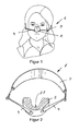
- the device 1 shows a device 1 fixed on the head of a teenager for reshaping nasal bones or for influencing the shape of the nose.
- the device comprises a molding device 2, which is connected via a connecting means 4 with a retaining device 3 running around the head at the rear.
- This device 1 is usually fixed overnight on the head, so that the molding device 2 exerts a pressing force on the skin and the underlying nasal bone during, for example, about eight hours.
- Figure 2 shows the device 1 shown in Figure 1 in detail.
- the shaping device 2 is shown in a cross section, so that the recess 21 for receiving the nose can be seen.
- the molding device 2 is designed in one piece and thus consists of a single part.
- the holding device 3 is preferably elastic and the connecting means 4 are preferably designed to be rigid so that the forming device 2 is pressed against the nose with a sufficiently large force and remains slip-resistant, in particular during sleep.
- the holding device 3 can be configured in various ways to be attached to the head. For example, the holding device 3 also two or have three behind the head extending bands to effect a better grip.
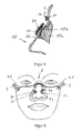
- FIG. 3 shows a longitudinal section through the molding apparatus 2 illustrated in FIG. 2.
- the course of the nose 17 is shown only schematically and by dashed lines.
- the nose has a bump 17b.
- the molding device 2 has at least one support surface 2b with a contact surface 2d that is intended to rest on the skin, so that the contact pressure exerted by the molding device 2 preferably takes place largely over the contact surface 2d.
- the bearing surface 2b is therefore designed with respect to orientation and / or size and / or surface profile such that the force generated via the contact surface 2d acts on a specific skin site and thus on a predetermined bone area 17b to influence its shape and / or growth.
- the contact surface 2d can be arranged and configured in various ways, and for example also consist of two or more partial surfaces, or for example along the entire length of the nose saddle or along the side contours.
- the arrangement, number, size and orientation of the contact surfaces 2d is determined by the position of the bone or cartilage regions whose shape and / or growth should be influenced. Therefore, it is also important that the forming device 2 can be reproducibly the same or similar arranged placed on the nose during preferably a larger number of applications, so that the pressing force is exerted on the same bone areas. Therefore, it may prove advantageous to provide the molding device 2 with a recess 21 configured in such a way that the molding device 2 can be placed on the nose virtually centering itself.
- the shaping device 2 is made, for example Made of plastic, wherein the molding device 2 may also have locally different elasticities.
- the shaping device 2 comprises a carrier 2a with an anatomically configured support surface 2b, the carrier 2a being connected to the connection means 4.
- the carrier 2a consists for example of a metallic frame 2m and an elastic plastic 2n, which forms the support surface 2b.
- the course of the inner contour of the carrier 2a corresponds to the course of the outer contour of the root of the nose, so that the carrier 2a can be applied to the face so that the carrier 2a surrounds the noses and rests on the nose over the support surface 2b on the face.
- This extensive and determined by the position of the nose application of the carrier 2a has the advantage that the carrier 2a reproducibly the same and slip resistant or substantially slip resistant, similar as shown in Figure 1, can be created.
- the carrier 2a or its metal frame 2m thus forms a base part to which one or more pressing bodies 2c can be fastened.
- a pressing body 2c is firmly connected to the carrier 2a via two holding means 2e formed as webs.
- the pressing body 2c has a contact surface 2d. It could also be several Anpress stresses 2c connected to the carrier 2a.
- the pressing bodies 2c could also be connected to the carrier 2a only with a single holding means 2e.
- the pressing bodies 2c could also be arranged to be displaceable and / or detachable and fixable with respect to the holding means 2e.
- the carrier 2a shown in FIG. 4 can thus be fitted in 2 different ways with Anpress emotionsn 2c.
- FIG. 5 schematically shows a longitudinal section through a nose 17 with a nasal bone 17a.
- the molding device 2 shown in Figure 4 is placed on the nose 17, the molding device 2 shown in Figure 4 is placed.
- the pressing body 2c with contact surface 2d bears against the nasal protuberance 17b, and exerts a contact force acting on the nasal protuberance 17b or on the nasal bone 17a.
- the pressing body 2c or the contact surface 2d can, as already described with FIG. 3, be designed and arranged in a large number of ways, depending on the respective anatomical shape of the nose. It is also possible to provide a plurality of contact surfaces 2d or even a plurality of contact bodies 2c.
- FIG. 6 schematically shows a forming device 2 with a carrier 2a, on which two pressing bodies 2c are arranged, each pressing body 2c being fixedly connected to the carrier 2a via a holding means 2e.
- the pressing bodies 2c are detachably connected to the respective holding means 2e, so that the pressing bodies 2c can be exchanged.
- the carrier 2a is connected to the holding device 3 with rigid connecting means 4 or via a face bow 5.
- FIG. 7 shows a further embodiment of a forming device 2 with carrier 2a and two pressing bodies 2c.
- a U-shaped designed holding means 2e is connected at both ends to the carrier 2a, wherein a pressing body 2c is attached to the U-shaped holding means 2e.
- the holding means 2e is over a as a face bow. 5 designed connecting means 4 connected to the holding device 3.
- the entire shaping device 2 is thus connected to the holding device 3 via the face bow 5.
- Face bow 5 is understood to mean a rigid, curved wire which transfers the force from the shaping device 2 to the holding device 3.
- the face bow 5 is preferably designed to be curved or arched so that it does not bear against the skin, and thus connect the shaping device 2 to the holding device 3 without touching the skin.
- the shaping device 2 could be connected to the holding device 3 simultaneously both via the connecting means 4 shown in FIG. 6 and via the face bow 5 shown in FIG.
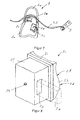
- FIG. 8 shows an embodiment of a pressing body 2c in detail.
- the pressing body 2c comprises a base part 2f with a recess 2g, wherein, as indicated by dashed lines, a carrier 2a or a holding means 2e extends through the recess 2g so that the pressing body 2c is slidably mounted with respect to the carrier 2a or the holding means 2e, and with a Screw 2h can be fixed.
- the pressing body 2c comprises a base plate 2i on which a molded part 2k is arranged.
- the molded part 2k has on the side opposite the base plate 2i a surface 21, which is preferably designed to extend three-dimensionally, wherein the surface 21 forms at least one defined contact surface 2d, which is indicated in Figure 8.
- the molded part 2k is preferably made of a skin-friendly material, for example a plastic.
- an Anpress stresses 2c has the advantage that the course of the surface 21 can be configured individually, whereas the other parts of the Anpress stressess 2c may be formed as identically designed standard parts.
- Each pressing body 2c is preferably provided with a mold part 2k which extends in accordance with the individual requirements or with an individually extending surface 21.
- FIG. 9 shows in detail how the contact bodies 2c shown in FIG. 8 could be fastened to a holding means 2e, for example the forming device 2 shown in FIG.
- FIG. 9 schematically shows a holding means 2e to which the two pressing bodies 2c are firmly fixed by means of screws 2h.
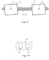
- FIG. 10 schematically shows a further molded part 2k which, in contrast to the exemplary embodiment shown in FIG. 8, is connected to two pressing bodies 2c.
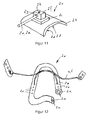
- FIG. 11 shows a further embodiment of a pressing body 2c.
- the pressing body 2c comprises a base part 2f with a recess 2g into which a holding means 2e protrudes.
- the holding means 2e is detachably connected to the base part 2f by means of the screw 2h.
- the pressing body 2c also comprises a molded part 2k, which is connected to the base part 2f via the base plate 2i.
- the molded part 2k has a surface 21 which forms a contact surface 2d.
- FIG. 12 shows a further exemplary embodiment of a carrier 2a with a round, metallic frame or a plastic frame 2m as well as an elastic plastic 2n enclosing the frame 2m.
- the metallic frame or the plastic frame 2m may be designed as flexible in an advantageous embodiment, so that the course of the frame 2m, for example, the anatomical profile of the nose or the root of the nose can be adjusted accordingly.
- Each leg of the carrier 2a is connected via a respective face bow 5 with the holding device 3.
- the two facial arches 5 are firmly connected to each other at the intersection.
- FIG. 13 shows in a detailed view how a holding means 2e or a face bow 5 can be connected to the carrier 2a.
- the carrier 2a has in the plastic 2n a hole 2o, which open into an internal thread 2p of the frame 2m.
- the holding means 2e or the face bow 5 has an external thread, which is screwed firmly to the internal thread 2p, so that the holding means 2e is firmly and detachably connected to the carrier 2a.
- the connection of frame 2m and holding means 2e could also be done via a plug or snap connection.
- the carrier 2a may have a plurality of such holes 2o, via which a pressing body 2c, for example the pressing body 2c shown in FIG. 11, can be connected to the carrier 2a. As shown in FIG.
- this plurality of holes 20 has the advantage that the pressing body 2c can be fastened in a large number of possible positions with respect to the carrier 2a or with respect to the nose 17. It is also possible to connect a plurality of AnpressMechn 2c firmly with a carrier 2a. In preferably opposite holes 2o, for example, as shown in Figure 7, a u-shaped holding means 2e can be anchored. It could also be a plurality in the longitudinal direction of the nose spaced holding means 2e connected to the carrier 2a.
- a kit or a kit when adapting the molding device 2, which has a plurality of carriers 2a of different size and / or shape, and a plurality of pressing bodies 2c, preferably also of different size and / or shape, and a plurality different face bow 5 includes.
- a kit makes it possible to form a plurality of differently designed, individually adapted to the anatomy of a human form devices 2.
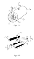
- FIG. 14 shows a further exemplary embodiment of a pressing body 2c, which is connected via a holding means 2p to a carrier 2a or a holding means 2e.
- the pressing body 2c comprises a preformed base plate 2i of preferably solid material such as metal or plastic, as well as a soft molded part 2k, for example of foam.
- the holding means 2p comprises two base parts 2f, the one base part 2f being fixedly and detachably connected to the carrier 2a or the holding means 2e by means of the screw 2h. After loosening the screw 2h, the base part 2f can be displaced along the carrier 2a or the holding means 2e.
- the base part 2f arranged at the bottom in FIG. 14 is firmly connected to the base plate 2i.
- the two base parts 2f have oppositely extending internal threads, in which a distance setting thread 2o is rotatably mounted, so that the distance between the two base parts 2f by turning the distance adjustment thread 20 can be increased or reduced.
- a key 2m may be inserted into a hole of the distance adjusting thread 2o and then rotated in the direction of movement A to thereby enlarge or reduce the overall length of the holding means 2p, thereby to act on the nose To increase or decrease the contact force.
- the key 2m is preferably inserted only for adjusting the holding means 2p in the distance adjusting thread 2o, and then completely removed.
- a plurality of holding means 2e which are detachably or fixedly connected to the carrier 2a, may also be arranged on the carrier 2a.
- the holding means 2e can also be configured in the form of a lattice, with, for example, firmly connected crossing points.
- the holding means 2e are advantageously configured as a thin wire of, for example, 1 mm, or 0.5 mm to 1.5 mm in diameter, wherein the grid is curved in such a way that, when the forming device 2 is attached, it extends at a distance from the nose.
- Such a carrier 2a with holding means 2e may have a very low weight.
- a Anpress redesign 2c used which has intersecting grooves 2n.
- This Pressing body 2c as shown in FIG. 16, is advantageously connected to them at intersecting holding means 2e, eg by soldering or gluing, so that the pressing body 2c is held in a precisely defined position in the grid or in the forming device 2.
- the contact body 2c can also be replaced by another contact body 2c.
- FIG. 17 shows a cross section through a further exemplary embodiment of a pressing body 2c.
- the Anpress stresses 2c according to Figure 17 in addition to a molded part 2k, which forms the contact surface 2d.
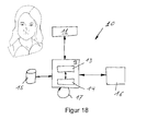
- FIG. 18 schematically shows a device 10 for producing the molding device 2.
- the creation of a molding device 2 for shaping the nose is shown.
- the same device 10 is also suitable for creating molding devices 2 for other body parts.
- the shape of the nose is scanned with a 3-dimensional scanner 11 and the data is transmitted to a server 12.
- a 3-dimensional data model of the measured shape of the nose is stored.
- the server has access to a database 15 in which the data of a plurality of forming devices 2, carriers 2a, pressing bodies 2c, etc. are stored.
- the processing module 13 stored in the server 12 is capable of, based on To propose the construction of a suitable shaping device 2 to the named, available data.
- the entire molding apparatus 2 may be assembled based on standard components, for example.
- the surface profile of the molded part 2k of each pressing body 2c is configured individually, for example, by connecting the server 12 to a machine 16, which allows to produce a molded part 2k with an individually extending surface 21.
- the pressing bodies 2c are provided in their basic form with a constantly thick molded part 2k. This molded part 2k can be processed individually in the machine 16, so that the molded part 2k produced in this way has an individually extending surface 21, with at least one contact surface 2d.
- the at least one pressing body 2c is then attached to the carrier 2a, so that the forming device 2 is formed, which can then be applied with a biasing force to the nose to influence the shape thereof.
Landscapes
- Health & Medical Sciences (AREA)
- Otolaryngology (AREA)
- Pulmonology (AREA)
- Nursing (AREA)
- Orthopedic Medicine & Surgery (AREA)
- Engineering & Computer Science (AREA)
- Biomedical Technology (AREA)
- Heart & Thoracic Surgery (AREA)
- Vascular Medicine (AREA)
- Life Sciences & Earth Sciences (AREA)
- Animal Behavior & Ethology (AREA)
- General Health & Medical Sciences (AREA)
- Public Health (AREA)
- Veterinary Medicine (AREA)
- Orthopedics, Nursing, And Contraception (AREA)
- Transplanting Machines (AREA)
- Blow-Moulding Or Thermoforming Of Plastics Or The Like (AREA)
Abstract
Description
Die Erfindung betrifft eine Vorrichtung zum Umformen von Knochen beziehungsweise zur Beeinflussung des Knochenwachstums, insbesondere des Nasenbeins. Die Erfindung betrifft weiter ein Verfahren zum Herstellen einer Vorrichtung zum Umformen von Knochen.The invention relates to a device for reshaping of bone or for influencing the bone growth, in particular of the nasal bone. The invention further relates to a method for producing a device for reshaping bones.
Die Form der Nase ist für ein attraktives Gesichtsprofil von zentraler Bedeutung. Idealerweise ist die Nase harmonisch verlaufend in den Gesichtszügen eingebettet. Weist die Nase jedoch eine eigenwillige Form und/oder eine überproportionale Grösse auf, so wird die Nase unweigerlich zum Blickfang und dadurch zum dominanten Teil des Gesichtes.The shape of the nose is central to an attractive facial profile. Ideally, the nose is embedded harmoniously in the facial features. However, if the nose has an idiosyncratic shape and / or a disproportionate size, the nose will inevitably become an eye-catcher and thus the dominant part of the face.
Die Form der Nase kann heute üblicherweise durch einen verhältnismäßig kleinen, aber dennoch sehr anspruchsvollen chirurgischen Eingriff dauerhaft korrigiert werden. In über 80 Prozent der Eingriffe wird die Nase verkleinert, in den übrigen die Nase vergrößert.The shape of the nose can today usually be permanently corrected by a relatively small but nevertheless very demanding surgical procedure. In more than 80 percent of the procedures, the nose is reduced in size, in the others the nose is enlarged.
Im Wesentlichen besteht die Nase aus knöchernen und knorpeligen Anteilen, die ein pyramidenförmiges Gerüst unter der bedeckenden Nasenhaut bilden. Senkrecht in der Mitte befindet sich die Nasenscheidewand, die im vorderen Anteil knorpelig, im hinteren Anteil knöchern ist. Bei Nasenoperationen gilt es, dieses Gerüst so zu gestalten, dass sich die äußere Form der Nase durch die bedeckende Haut verändert. Die Rhinoplastik kann die Nase verkleinern oder vergrößern, die Form des Nasenrückens sowie des Naseneinganges mit den Nasenflügeln und den Nasenlöchern korrigieren, sowie die Länge der Nase und den Winkel zwischen Nase und Oberlippe verändern. Der Eingriff wird insbesondere aus ästhetischen Gründen zur Harmonisierung der Nase und des gesamten Gesichtes (ästhetische Rhinoplastik) durchgeführt. Damit der Eingriff keine sichtbaren Spuren hinterlässt, werden die Hautschnitte im Naseninneren oder am Nasensteg angelegt. Durch diesen Zugang modelliert der Arzt das Knochen- und Knorpelgerüst der Nase je nach Zielsetzung vorteilhaft um. So kann die Nase zum Beispiel verkleinert, verschmälert oder begradigt werden. Eine derartige Korrektur der Nase sollte erst nach Abschluss des Knochenwachstums, also etwa ab dem 16. oder 17. Lebensjahr vorgenommen werden.Essentially, the nose consists of bony and cartilaginous parts, which form a pyramidal framework under the covering nose skin. Vertically in the middle is the nasal septum, which is cartilaginous in the anterior part, bony in the posterior part. In nasal surgery, this scaffolding must be designed so that the outer shape of the nose is changed by the covering skin. The rhinoplasty can make the nose smaller or larger, correct the shape of the nose and nose with the nostrils and nostrils, and change the length of the nose and the angle between the nose and upper lip. The procedure is performed especially for aesthetic reasons to harmonize the nose and the entire face (aesthetic rhinoplasty). So that the procedure leaves no visible traces, the incisions are made in the inside of the nose or at the bridge of the nose. Through this approach, the doctor advantageously models the bone and cartilage framework of the nose depending on the objective. For example, the nose can be downsized, narrowed or straightened. Such correction of the nose should be made only after the completion of bone growth, ie about the age of 16 or 17 years.
Dieses bekannte Verfahren weist die Nachteile auf, dass ein anspruchsvoller chirurgischer Eingriff mit all den damit verbundenen Risiken erforderlich ist, dass der Eingriff sehr teuer ist und üblicherweise von den Krankenkassen nicht finanziert wird, und dass das Verfahren aus finanziellen Gründen nur einer begrenzten Bevölkerung zugänglich ist.This known method has the disadvantages that a sophisticated surgical procedure with all the associated risks is required, that the procedure is very expensive and is usually not financed by the health insurance companies, and that the method is only accessible to a limited population for financial reasons ,
Aufgabe der Erfindung ist es, eine Vorrichtung, sowie ein Verfahren zum Herstellen der Vorrichtung vorzuschlagen, welche ein kostengünstiges und sicheres Umformen von Knochen, und insbesondere eine Korrektur der Nasenform ermöglicht.The object of the invention is to provide a device and a method for producing the device, which allows a cost-effective and secure reshaping of bones, and in particular a correction of the nose shape.
Diese Aufgabe wird gelöst mit einer Vorrichtung zum Umformen von Knochen oder Knorpel aufweisend die Merkmale von Anspruch 1. Die Unteransprüche 2 bis 12 betreffen weitere, vorteilhafte Ausgestaltungen. Die Aufgabe wird weiter gelöst mit einem Verfahren zum Herstellen der erfindungsgemässen Vorrichtung aufweisend die Merkmale von Anspruch 13.This object is achieved with a device for reshaping of bones or cartilage having the features of
Die Aufgabe wird insbesondere gelöst mit einer Vorrichtung zum Umformen von Knochen beziehungsweise zum Beeinflussen des Wachstums von Knochen oder Knorpel, insbesondere Nasenknochen, umfassend eine Formvorrichtung mit einer zur Auflage auf die Haut bestimmten Anpressfläche, und umfassend eine Haltevorrichtung, welche mit der Formvorrichtung verbindbar ist, wobei die Haltevorrichtung sowie die Formvorrichtung derart zusammenwirkend ausgestaltet ist, dass die Formvorrichtung zumindest an der Anpressfläche unter Ausübung einer Anpresskraft an der Haut anliegen kann.The object is in particular achieved with a device for reshaping bones or influencing the growth of bones or cartilage, in particular nasal bones, comprising a shaping device with a contact surface intended for resting on the skin, and comprising a holding device which is connectable to the forming device, wherein the holding device and the shaping device are designed cooperatively in such a way that the shaping device can rest on the skin at least on the contact surface while exerting a contact pressure.
Unter Knochen werden in der vorliegenden Schrift auch knochenähnliche Strukturen oder Knorpel verstanden.In the present document, bone is also understood to mean bone-like structures or cartilages.
Es hat sich herausgestellt, dass der Knochen des Menschen während des gesamten Lebens einem ständigen Umbauprozess unterworfen ist. Beim normalen Umbau des Knochens besteht ein Gleichgewicht zwischen osteoklastischer und osteoblastischer Aktivität. Eine dauernde Belastung des Knochens führt jedoch zu Anpassungsvorgängen wie Corticalisverdickung und Ausrichtung der Spongiosabälkchen. Wird die individuelle Belastungstoleranz durch wiederholte submaximale gleichartige Reize überschritten, finden im Bereich mechanischer Spannungsspitzen Strukturveränderungen und Umbauvorgänge statt. Die vorliegende Erfindung macht sich diesen Effekt zu nutzen, indem auf gewisse Knochenbereiche ein derartiger Druck erzeugt wird, sodass in diesem Knochen eine Spannung entsteht, welche die Ausformung des Knochens oder Knorpels beeinflusst. Dazu wird auf die Haut, welche sich über dem genannten Knochenbereich befindet, eine Kraft ausgeübt, welche sich über die Haut auf den Knochen fortpflanzt, sodass mit der erfindungsgemässen Formvorrichtung die Form des Knochens beeinflusst wird. Die erfindungsgemässe Vorrichtung wird vorzugsweise bei sich im Wachstum befindlichen Kindern verwendet, da die Ausgestaltung des Knochens, insbesondere des Nasenknochens, in dieser Phase relativ einfach beeinflussbar ist. Die erfindungsgemässe Vorrichtung ist jedoch auch für erwachsene Menschen verwendbar. Die erfindungsgemässe Vorrichtung wird vorzugsweise während mehreren Stunden pro Tag angewendet, beispielsweise während des Schlafs.It has been found that human bones undergo a constant process of remodeling throughout life is. During normal remodeling of the bone, there is a balance between osteoclastic and osteoblastic activity. However, a constant loading of the bone leads to adaptation processes such as corticalis thickening and alignment of the cancellous bone. If the individual load tolerance is exceeded by repeated submaximal, similar stimuli, structural changes and remodeling occur in the area of mechanical stress peaks. The present invention seeks to take advantage of this effect by creating such pressure on certain areas of the bone that a tension is created in that bone which affects the shape of the bone or cartilage. For this purpose, a force is exerted on the skin, which is located above the said bone area, which propagates via the skin to the bone, so that the shape of the bone is influenced by the inventive shaping device. The device according to the invention is preferably used in children growing up, since the configuration of the bone, in particular of the nasal bone, can be influenced relatively easily in this phase. However, the device according to the invention can also be used for adult humans. The device according to the invention is preferably used for several hours per day, for example during sleep.
Um beispielsweise die Nasenform zu korrigieren oder umzuformen wird die erfindungsgemässe Vorrichtung vor dem Schlafen gehen montiert, indem die Formvorrichtung auf die Nase gelegt wird, und die Formvorrichtung mit einer Haltevorrichtung am Kopf fixiert wird. Die Formvorrichtung weist Anpressflächen auf, welche derart ausgerichtet, angeordnet und ausgestaltet sind, dass während dem Schlafen auf eine vorherbestimmte Stelle des Nasenknochens eine Presskraft ausgeübt wird.To correct or reshape the nose shape, for example, the device according to the invention is mounted before going to sleep by placing the shaping device on the nose and fixing the shaping device to the head with a holding device. The molding device has contact surfaces, which are aligned, arranged and configured such that during the Sleeping on a predetermined site of the nasal bone a pressing force is exerted.
Durch üblicherweise mehrmonatiges bis jahrelanges Tragen der erfindungsgemässen Vorrichtung während des Schlafens verändert sich die Form des Nasenknochens, beziehungsweise der wachsende Nasenknochen gleicht sich einer vorgegebenen Form an. Dies wird vorzugsweise während der Wachstumsphase angewendet, damit der Nasenknochen nach Abschluss des Knochenwachstums, das heisst nach dem 16. bis 17. Lebensjahr, die gewünscht Nasenknochenform aufweist und diese auch beibehält.By usually several months to years of wearing the inventive device during sleep, the shape of the nasal bone changes, or the growing nasal bone is similar to a predetermined shape. This is preferably used during the growth phase, so that the nasal bone has the desired nasal bone shape after completion of bone growth, that is, after the 16th to 17th year of life, and this also retains.
Die erfindungsgemässe Vorrichtung wird nachfolgend am Beispiel der Umformung der Nase im Detail erläutert. Die erfindungsgemässe Vorrichtung ist jedoch zur Umformung beinahe jedes Knochens des Menschen geeignet, beispielsweise auch zur Umformung des Kinns oder der Backenknochen. Die Erfindung wird nachfolgend an Hand von Ausführungsbeispielen beschreiben.The inventive device is explained below using the example of the deformation of the nose in detail. However, the device according to the invention is suitable for reshaping almost any human bone, for example also for reshaping the chin or the cheekbones. The invention will be described below with reference to exemplary embodiments.
Die zur Erläuterung der Ausführungsbeispiele verwendeten Zeichnungen zeigen:
- Fig. 1
- eine montierte Vorrichtung zum Umformen von Knochen;
- Fig. 2
- die in
Figur 1 dargestellte Vorrichtung im Detail; - Fig. 3
- einen Längsschnitt durch die in
Figur 2 im Schnitt dargestellte, einstückige Formvorrichtung; - Fig. 4
- ein weiteres Ausführungsbeispiel einer Formvorrichtung;
- Fig. 5
- einen Längsschnitt durch die in
Figur 4 dargestellte und auf eine Nase aufgesetzte Formvorrichtung; - Fig. 6
- ein weiteres Ausführungsbeispiel einer Formvorrichtung;
- Fig. 7
- ein weiteres Ausführungsbeispiel einer Formvorrichtung;
- Fig. 8
- ein Ausführungsbeispiel eines Anpresskörpers;
- Fig. 9
- ein weiteres Ausführungsbeispiel einer Vorrichtung zum Umformen von Knochen;
- Fig. 10
- ein weiteres Ausführungsbeispiel eines Anpresskörpers;
- Fig. 11
- ein weiteres Ausführungsbeispiel eines Anpresskörpers;
- Fig. 12
- ein weiteres Ausführungsbeispiel eines Trägers;
- Fig. 13
- ein Detail des in
Figur 12 dargestellten Trägers; - Fig. 14
- ein weiteres Ausführungsbeispiel eines Trägers mit daran befestigtem Anpresskörper;
- Fig. 15
- ein weiteres Ausführungsbeispiel eines Anpresskörpers;
- Fig. 16
- ein weiteres Ausführungsbeispiel einer Formvorrichtung;
- Fig. 17
- einen Querschnitt durch ein weiteres Ausführungsbeispiel eines Anpresskörpers;
- Fig. 18
- eine Vorrichtung zum Herstellen der Vorrichtung zum Umformen von Knochen.
- Fig. 1
- an assembled bone reshaping device;
- Fig. 2
- the device shown in Figure 1 in detail;
- Fig. 3
- a longitudinal section through the one-piece molding device shown in section in Figure 2;
- Fig. 4
- another embodiment of a molding apparatus;
- Fig. 5
- a longitudinal section through the illustrated in Figure 4 and placed on a nose molding device;
- Fig. 6
- another embodiment of a molding apparatus;
- Fig. 7
- another embodiment of a molding apparatus;
- Fig. 8
- an embodiment of a pressing body;
- Fig. 9
- a further embodiment of an apparatus for reshaping bones;
- Fig. 10
- a further embodiment of a pressing body;
- Fig. 11
- a further embodiment of a pressing body;
- Fig. 12
- another embodiment of a carrier;
- Fig. 13
- a detail of the carrier shown in Figure 12;
- Fig. 14
- a further embodiment of a carrier with Anpresskörper attached thereto;
- Fig. 15
- a further embodiment of a pressing body;
- Fig. 16
- another embodiment of a molding apparatus;
- Fig. 17
- a cross section through a further embodiment of a pressing body;
- Fig. 18
- a device for producing the device for forming bone.
Grundsätzlich sind in den Zeichnungen gleiche Teile mit gleichen Bezugszeichen versehen.Basically, the same parts are given the same reference numerals in the drawings.
Fig. 1 zeigt eine am Kopf eines Teenagers fixierte Vorrichtung 1 zum Umformen von Nasenknochen beziehungsweise zur Beeinflussung der Form der Nase. Die Vorrichtung umfasst eine Formvorrichtung 2, welche über ein Verbindungsmittel 4 mit einer hinten um den Kopf verlaufenden Haltevorrichtung 3 verbunden ist. Diese Vorrichtung 1 wird üblicherweise über Nacht am Kopf fixiert, sodass die Formvorrichtung 2 während beispielsweise etwa acht Stunden eine Anpresskraft auf die Haut und den darunter liegenden Nasenknochen ausübt.1 shows a
Figur 2 zeigt die in Figur 1 dargestellte Vorrichtung 1 im Detail. Die Formvorrichtung 2 ist in einem Querschnitt dargestellt, sodass die zur Aufnahme der Nase bestimmte Ausnehmung 21 ersichtlich ist. Die Formvorrichtung 2 ist einstückig ausgestaltet und besteht somit aus einem einzigen Teil. Die Haltevorrichtung 3 ist vorzugsweise elastische und die Verbindungsmittel 4 sind vorzugsweise starr ausgestaltet, damit die Formvorrichtung 2 mit genügend grosser Kraft gegen die Nase gepresst wird und verrutschfest bleibt, insbesondere während dem Schlaf. Die Haltevorrichtung 3 kann auf unterschiedlichste Weise ausgestaltet sein, um am Kopf befestigt zu werden. Beispielsweise kann die Haltevorrichtung 3 auch zwei oder drei hinter dem Kopf verlaufende Bänder aufweisen, um einen besseren Halt zu bewirken.Figure 2 shows the
Figur 3 zeigt einen Längsschnitt durch die in Figur 2 dargestellte Formvorrichtung 2. Nur schematisch und gestrichelt ist der Verlauf der Nase 17 dargestellt. Die Nase weist einen Höcker 17b auf. Die Formvorrichtung 2 weist zumindest eine zur Auflage auf die Haut bestimmte Auflagefläche 2b mit Anpressfläche 2d auf, sodass die von der Formvorrichtung 2 ausgeübte Anpresskraft vorzugsweise zum grossen Teil über die Anpressfläche 2d erfolgt. Die Auflagefläche 2b ist daher derart bezüglich Ausrichtung und/oder Grösse und/oder Oberflächenverlauf ausgestaltet, dass die über die Anpressfläche 2d erzeugte Kraft auf eine bestimmte Hautstelle und somit auf einen vorherbestimmten Knochenbereich 17b einwirkt, um dessen Form und/oder Wachstum zu beeinflussen. Die Anpressfläche 2d kann auf unterschiedlichste Weise angeordnet und ausgestaltet sein, und beispielsweise auch aus zwei oder mehreren Teilflächen bestehen, oder beispielsweise entlang der gesamten Länge des Nasensattels oder entlang der Seitenkonturen verlaufen. Die Anordnung, Anzahl, Grösse und Ausrichtung der Anpressflächen 2d ist bestimmt durch die Lage der Knochen- beziehungsweise Knorpelbereiche, deren Form und/oder Wachstum beeinflusst werden sollten. Daher ist es auch wichtig, dass die Formvorrichtung 2 während vorzugsweise einer grösseren Anzahl Anwendungen reproduzierbar gleich oder ähnlich angeordnet auf die Nase aufgesetzt werden kann, damit die Anpresskraft auf dieselben Knochenbereiche ausgeübt wird. Daher kann es sich als vorteilhaft erweisen, die Formvorrichtung 2 mit einer derartig ausgestalteten Ausnehmung 21 zu versehen, dass die Formvorrichtung 2 quasi selbst zentrierend auf die Nase aufgesetzt werden kann. Die Formvorrichtung 2 ist beispielsweise aus Kunststoff gefertigt, wobei die Formvorrichtung 2 auch lokal unterschiedliche Elastizitäten aufweisen kann.FIG. 3 shows a longitudinal section through the
In einer vorteilhaften Ausgestaltung umfasst die Formvorrichtung 2, wie in Figur 4 dargestellt, einen Träger 2a mit anatomisch ausgestalteter Auflagefläche 2b, wobei der Träger 2a mit den Verbindungsmitteln 4 verbunden ist. Der Träger 2a besteht beispielsweise aus einem metallischen Rahmen 2m sowie einem elastischen Kunststoff 2n, welcher die Auflagefläche 2b ausbildet. Im dargestellten Ausführungsbeispiel entspricht der Verlauf der Innenkontur des Trägers 2a dem Verlauf der Aussenkontur der Nasenwurzel, sodass der Träger 2a derart am Gesicht angelegt werden kann, dass der Träger 2a die Nasen umschliesst und im Bereich der Nasenwurzel über die Auflagefläche 2b am Gesicht anliegt. Dieses grossflächige und durch die Lage der Nase bestimmte Anlegen des Trägers 2a weist den Vorteil auf, dass der Träger 2a reproduzierbar gleich und verrutschfest oder im Wesentlichen verrutschfest, ähnliche wie in Figur 1 dargestellt, angelegt werden kann. Der Träger 2a beziehungsweise dessen Metallrahmen 2m bildet somit eine Basisteil, an welchem ein oder mehrere Anpresskörper 2c befestigt werden können. Im dargestellten Ausführungsbeispiel ist ein Anpresskörper 2c über zwei als Stege ausgebildete Haltemittel 2e fest mit dem Träger 2a verbunden. Der Anpresskörper 2c weist eine Anpressfläche 2d auf. Es könnten auch mehrere Anpresskörper 2c mit dem Träger 2a verbunden sein. Die Anpresskörper 2c könnte auch nur mit einem einzigen Haltemittel 2e mit dem Träger 2a verbunden sein. Die Anpresskörper 2c könnten bezüglich dem Haltemittel 2e auch verschiebbar und/oder lösbar und wieder fixierbar angeordnet sein. Der in Figur 4 dargestellte Träger 2a kann somit auf unterschiedlichste Weise mit Anpresskörpern 2c bestückt werden.In an advantageous embodiment, as shown in FIG. 4, the
Figur 5 zeigt schematisch einen Längsschnitt durch eine Nase 17 mit Nasenknochen 17a. Auf die Nase 17 ist die in Figur 4 dargestellte Formvorrichtung 2 aufgesetzt. Der Anpresskörper 2c mit Anpressfläche 2d liegt am Nasenhöcker 17b an, und übt eine auf den Nasenhöcker 17b beziehungsweise auf den Nasenknochen 17a wirkende Anpresskraft aus. Der Anpresskörper 2c beziehungsweise die Anpressfläche 2d kann, wie bereits mit Figur 3 beschrieben, abhängig von der jeweiligen anatomischen Form der Nase, in einer Vielzahl von Möglichkeiten ausgestaltet und angeordnet sein. Es können auch mehrere Anpressflächen 2d oder auch eine Mehrzahl von Anpresskörper 2c vorgesehen sein.FIG. 5 schematically shows a longitudinal section through a
Figur 6 zeigt schematisch eine Formvorrichtung 2 mit einem Träger 2a, an welchem zwei Anpresskörper 2c angeordnet sind, wobei jeder Anpresskörper 2c über ein Haltemittel 2e mit dem Träger 2a fest verbunden ist. In einer bevorzugten Ausgestaltung sind die Anpresskörper 2c lösbar mit dem jeweiligen Haltemittel 2e verbunden, sodass die Anpresskörper 2c ausgetauscht werden können. Der Träger 2a ist mit starren Verbindungsmitteln 4 beziehungsweise über einen Gesichtsbogen 5 mit der Haltevorrichtung 3 verbunden.FIG. 6 schematically shows a forming
Figur 7 zeigt ein weiteres Ausführungsbeispiel einer Formvorrichtung 2 mit Träger 2a und zwei Anpresskörpern 2c. Ein u-förmig ausgestaltetes Haltemittel 2e ist an beiden Enden mit dem Träger 2a verbunden, wobei ein Anpresskörper 2c am u-förmigen Haltemittel 2e befestigt ist. Das Haltemittel 2e ist über ein als Gesichtsbogen 5 ausgestaltetes Verbindungsmittel 4 mit der Haltevorrichtung 3 verbunden. Die gesamte Formvorrichtung 2 ist somit über den Gesichtsbogen 5 mit der Haltevorrichtung 3 verbunden. Unter Gesichtsbogen 5 wird ein starrer, gekrümmt verlaufender Draht verstanden, welche die Kraft von der Formvorrichtung 2 zur Haltevorrichtung 3 überträgt. Der Gesichtsbogen 5 ist vorzugsweise derart gekrümmt beziehungsweise gewölbt verlaufend ausgestaltet, dass dieser nicht an der Haut anliegt, und somit die Formvorrichtung 2 mit der Haltevorrichtung 3 verbinden, ohne die Haut zu berühren.FIG. 7 shows a further embodiment of a forming
In einem weiteren, nicht dargestellten Ausführungsbeispiel könnte die Formvorrichtung 2 gleichzeitig sowohl über das in Figur 6 dargestellte Verbindungsmittel 4 als auch über den in Figur 7 dargestellten Gesichtsbogen 5 mit der Haltevorrichtung 3 verbunden sein.In a further, not shown embodiment, the
Figur 8 zeigt ein Ausführungsbeispiel eines Anpresskörpers 2c im Detail. Der Anpresskörper 2c umfasst ein Basisteil 2f mit einer Ausnehmung 2g, wobei, wie gestrichelt angedeutet, ein Träger 2a beziehungsweise ein Haltemittel 2e durch die Ausnehmung 2g verläuft, sodass der Anpresskörper 2c bezüglich dem Träger 2a beziehungsweise dem Haltemittel 2e verschiebbar gelagert ist, und mit einer Schraube 2h fixiert werden kann. Der Anpresskörper 2c umfasst eine Basisplatte 2i, auf welcher ein Formteil 2k angeordnet ist. Das Formteil 2k weist auf der der Basisplatte 2i gegenüberliegenden Seite eine Oberfläche 21 auf, welche vorzugsweise dreidimensional verlaufend ausgestaltet ist, wobei die Oberfläche 21 zumindest eine definierte Anpressfläche 2d ausbildet, welche in Figur 8 angedeutet ist. Das Formteil 2k ist vorzugsweise aus einem hautfreundlichen Material, beispielsweise einem Kunststoff gefertigt.FIG. 8 shows an embodiment of a
Das in Figur 8 dargestellte Ausführungsbeispiel eines Anpresskörpers 2c weist den Vorteil auf, dass der Verlauf der Oberfläche 21 individuell ausgestaltet werden kann, wogegen die übrigen Teile des Anpresskörpers 2c als identisch ausgestaltete Standardteile ausgebildet sein können. Ebenso ist es möglich die Anpresskörper 2c in wenigen unterschiedlichen Grössen, zum Beispiel in drei bis vier Einheitsgrössen zu fertigen, sodass eine Formvorrichtung 2 mit Hilfe eines Trägers 2a und einer Mehrzahl der standardisierten Anpresskörper 2c zusammengebaut werden kann. Jeder Anpresskörper 2c wird vorzugsweise mit einem den individuellen Bedürfnissen angepasst verlaufenden Formteil 2k beziehungsweise mit einer individuell verlaufenden Oberfläche 21 versehen.The illustrated in Figure 8 embodiment of an
Figur 9 zeigt im Detail, wie die in Figur 8 dargestellten Anpresskörper 2c an einem Haltemittel 2e, beispielsweise der in Figur 6 dargestellten Formvorrichtung 2 befestigt werden könnten. Figur 9 zeigt schematisch ein Haltemittel 2e, an welchem die zwei Anpresskörper 2c mit Hilfe von Schrauben 2h fest fixiert sind.FIG. 9 shows in detail how the
Figur 10 zeigt schematisch ein weiteres Formteil 2k, welches im Unterschied zu dem in Figur 8 dargestellten Ausführungsbeispiel, mit zwei Anpresskörpern 2c verbunden ist.FIG. 10 schematically shows a further molded
Figur 11 zeigt ein weiteres Ausführungsbeispiel eines Anpresskörpers 2c. Der Anpresskörper 2c umfasst ein Basisteil 2f mit einer Ausnehmung 2g, in welche ein Haltemittel 2e hineinragt. Das Haltemittel 2e ist mit Hilfe der Schraube 2h lösbar mit dem Basisteil 2f verbunden. Der Anpresskörper 2c umfasst zudem ein Formteil 2k, welches über die Basisplatte 2i mit dem Basisteil 2f verbunden ist.FIG. 11 shows a further embodiment of a
Das Formteil 2k weist eine Oberfläche 21 auf, welche eine Anpressfläche 2d ausbildet.The molded
Figur 12 zeigt ein weiteres Ausführungsbeispiel eines Trägers 2a mit einem runden, metallischen Rahmen oder einem Kunststoffrahmen 2m sowie einem den Rahmen 2m umschliessenden elastischen Kunststoff 2n. Der metallische Rahmen oder der Kunststoffrahmen 2m kann in einer vorteilhaften Ausführungsform als biegsam ausgestaltet sein, sodass der Verlauf des Rahmens 2m beispielsweise dem anatomischen Verlauf der Nase beziehungsweise der Nasenwurzel entsprechend angepasst werden kann. Jeder Schenkel des Trägers 2a ist über je einen Gesichtsbogen 5 mit der Haltevorrichtung 3 verbunden. Die beiden Gesichtsbögen 5 sind an deren Kreuzungsstelle fest miteinander verbunden.
Figur 13 zeigt in einer Detailansicht, wie ein Haltemittel 2e beziehungsweise ein Gesichtsbogen 5 mit dem Träger 2a verbindbar ist. Der Träger 2a weist im Kunststoff 2n ein Loch 2o auf, welches in ein Innengewinde 2p des Rahmens 2m münden. Das Haltemittel 2e beziehungsweise der Gesichtsbogen 5 weist ein Aussengewinde auf, welches fest mit dem Innengewinde 2p verschraubbar ist, sodass das Haltemittel 2e fest und lösbar mit dem Träger 2a verbunden ist. Anstelle eines Gewindes könnte die Verbindung von Rahmen 2m und Haltemittel 2e auch über eine Steck- oder Schnappverbindung erfolgen. Der Träger 2a kann eine Mehrzahl derartiger Löcher 2o aufweisen, über welche ein Anpresskörper 2c, beispielsweise der in Figur 11 dargestellte Anpresskörper 2c, mit dem Träger 2a verbindbar ist. Diese Mehrzahl von Löchern 2o weist, wie in Figur 12 dargestellt, den Vorteil auf, dass der Anpresskörper 2c in einer Vielzahl möglicher Positionen bezüglich dem Träger 2a beziehungsweise bezüglich der Nase 17 befestigbar ist. Zudem ist es möglich eine Mehrzahl von Anpresskörpern 2c fest mit einem Träger 2a zu verbinden. In vorzugsweise gegenüberliegenden Löchern 2o könne beispielsweise auch, wie in Figur 7 dargestellt, ein u-förmiges Haltemittel 2e verankert werden. Es könnten auch eine Mehrzahl in Längsrichtung der Nase beabstandet angeordnete Haltemittel 2e mit dem Träger 2a verbunden sein.FIG. 12 shows a further exemplary embodiment of a
FIG. 13 shows in a detailed view how a holding means 2e or a face bow 5 can be connected to the
In einer vorteilhaften Ausgestaltung steht beim Anpassen der Formvorrichtung 2 ein Bausatz beziehungsweise ein Kit zur Verfügung, welcher eine Mehrzahl von Trägern 2a unterschiedlicher Grösse und/oder Gestalt, sowie eine Mehrzahl von Anpresskörpern 2c, vorzugsweise auch unterschiedlicher Grösse und/oder Gestalt, sowie eine Mehrzahl unterschiedlicher Gesichtsbogen 5 umfasst. Ein derartiger Bausatz ermöglicht es eine Vielzahl unterschiedlich ausgestalteter, individuell an die Anatomie eines Menschen angepasste Formvorrichtungen 2 zu bilden.In an advantageous embodiment, when adapting the
Figur 14 zeigt ein weiteres Ausführungsbeispiel eines Anpresskörpers 2c, welcher über ein Haltemittel 2p mit einem Träger 2a oder einem Haltemittel 2e verbunden ist. Der Anpresskörper 2c umfasst eine vorgeformte Basisplatte 2i aus vorzugsweise festem Material wie Metall oder Kunststoff, sowie eine weiches Formteil 2k, beispielsweise aus Schaumstoff. Das Haltemittel 2p umfasst zwei Basisteile 2f, wobei das eine Basisteil 2f mit Hilfe der Schraube 2h fest und lösbar mit dem Träger 2a oder dem Haltemittel 2e verbunden ist. Nach dem Lösen der Schraube 2h kann das Basisteil 2f entlang des Trägers 2a beziehungsweise des Haltemittels 2e verschoben werden. Das in Figur 14 unten angeordnete Basisteil 2f ist fest mit der Basisplatte 2i verbunden. Die beiden Basisteile 2f weisen entgegengesetzt verlaufende Innengewinde auf, in welchen ein Distanzeinstellgewinde 2o verdrehbar gelagert ist, sodass die Distanz zwischen den beiden Basisteilen 2f durch Drehen des Distanzeinstellgewindes 20 vergrösserbar oder verkleinerbar ist. Um das Distanzeinstellgewinde 20 zu verdrehen kann, wie dargestellt, ein Schlüssel 2m in ein Loch des Distanzeinstellgewindes 2o eingeführt und anschliessend in Bewegungsrichtung A gedreht werden, um dadurch die Gesamtlänge des Haltemittel 2p zu vergrössern oder zu verkleinern, beziehungsweise um dadurch die auf die Nase wirkende Anpresskraft zu vergrössern oder zu verkleinern. Der Schlüssel 2m wird vorzugsweise nur zum Verstellen des Haltemittels 2p in das Distanzeinstellgewinde 2o eingeführt, und danach wieder vollständig entfernt. Die Verwendung eines derartigen Schlüssel 2m weist den Vorteil auf, dass dieser relativ lang ausgestaltet sein kann, sodass mit Hilfe dieses Schlüssels 2m ein relativ grosses Drehmoment auf das Distanzeinstellgewinde 2o bewirkt werden kann, sodass der Anpresskörper 2c, falls erforderlich, auch mit einer hohen Anpresskraft versehen werden kann.FIG. 14 shows a further exemplary embodiment of a
Am Träger 2a könnten auch, wie in Figur 16 in einer Draufsicht dargestellt, eine Mehrzahl von Haltemitteln 2e angeordnet sein, welche lösbar oder fest mit dem Träger 2a verbunden sind. Die Haltemittel 2e können auch gitterförmig ausgestaltet sein, mit zum Beispiel fest verbundenen Kreuzungspunkten. Die Haltemittel 2e sind vorteilhafterweise als dünner Draht von beispielsweise 1 mm, oder 0.5 mm bis 1.5 mm, Durchmesser ausgestaltet, wobei das Gitter derart gewölbt ist, dass dieses bei aufgesetzter Formvorrichtung 2 bezüglich der Nase beabstandet verläuft. Ein derartiger Träger 2a mit Haltemittel 2e kann ein sehr geringes Gewicht aufweisen. Vorteilhafterweise wird, wie in Figur 15 dargestellt, ein Anpresskörper 2c verwendet, der sich kreuzende Nuten 2n aufweist. Dieser Anpresskörper 2c wird, wie in Figur 16 dargestellt, vorteilhafterweise an sich kreuzenden Haltemitteln 2e mit diesen verbunden, z.B. durch Löten oder Kleben, sodass der Anpresskörper 2c in einer genau definierten Lage im Gitter beziehungsweise in der Formvorrichtung 2 gehalten ist. Falls erforderlich kann der Anpresskörper 2c auch durch einen anderen Anpresskörper 2c ersetzt werden. Es wäre jedoch auch ein Anpresskörper 2c ohne kreuzende Nuten geeignet, welcher am Gitter befestigt werden kann. Es könnten auch eine Mehrzahl von Anpresskörper 2c am Gitter befestigt werden.As shown in FIG. 16 in a plan view, a plurality of holding means 2e, which are detachably or fixedly connected to the
Figur 17 zeigt einen Querschnitt durch ein weiteres Ausführungsbeispiel eines Anpresskörpers 2c. Im Unterschied zu dem in Figur 15 dargestellten Ausführungsbeispiel weist der Anpresskörper 2c gemäss Figur 17 zusätzlich ein Formteil 2k auf, welche die Anpressfläche 2d ausbildet.FIG. 17 shows a cross section through a further exemplary embodiment of a
Figur 18 zeigt schematisch eine Vorrichtung 10 zum Herstellen der Formvorrichtung 2. Im dargestellten Ausführungsbeispiel wird die Erstellung einer Formvorrichtung 2 zum Umformen der Nase dargestellt. Dieselbe Vorrichtung 10 ist natürlich auch zum Erstellen von Formvorrichtungen 2 für andere Körperteile geeignet. Die Form der Nase wird mit einem 3-dimensionalen Scanner 11 abgetastet und die Daten einem Server 12 übermittelt. Im Speicher 14 wird ein 3-dimensionales Datenmodell der ausgemessenen Form der Nase bespeichert. Daraufhin kann mit Hilfe eines interaktiven Verfahrens 17 ein 3-dimensionales Datenmodell der gewünschten Nasenform gespeichert werden. Der Server hat Zugriff auf eine Datenbank 15, in welcher die Daten einer Mehrzahl von Formvorrichtungen 2, Trägern 2a, Anpresskörper 2c usw. gespeichert sind. Das im Server 12 gespeicherte Verarbeitungsmodul 13 ist in der Lage, basierend auf den genannten, zur Verfügung stehenden Daten den Aufbau einer geeigneten Formvorrichtung 2 vorzuschlagen. Die gesamte Formvorrichtung 2 kann beispielsweise basierend auf Standartkomponenten zusammengestellt werden. In einer bevorzugten Ausgestaltung wird der Oberflächenverlauf des Formteils 2k jedes Anpresskörpers 2c individuell ausgestaltet, indem beispielsweise der Server 12 mit einer Maschine 16 verbunden ist, welche ein Formteil 2k mit individuell verlaufender Oberfläche 21 herzustellen erlaubt. In einer vorteilhaften Ausgestaltung sind die Anpresskörper 2c in ihrer Grundform mit einem konstant dicken Formteil 2k versehen. Dieses Formteil 2k kann in der Maschine 16 individuell bearbeitet werden, sodass das derart gefertigte Formteil 2k eine individuell verlaufende Oberfläche 21 aufweist, mit zumindest einer Anpressfläche 2d. Der zumindest eine Anpresskörper 2c wird daraufhin am Träger 2a befestigt, sodass die Formvorrichtung 2 ausgebildet wird, welche daraufhin mit einer Vorspannkraft an die Nase angelegt werden kann, um deren Form zu beeinflussen.FIG. 18 schematically shows a
Das Verfahren zum Herstellen einer Formvorrichtung umfasst in einer bevorzugten Ausgestaltung die folgenden Schritte:
- a) Berührungsloses Abtasten der zu verändernden Hautoberfläche und Erstellen eines digitalen Modells des Verlaufs der Hautoberfläche der zu verändernden Körperstelle;
- b) Erhalten eines digitalen Modells des Verlaufs der darunter liegenden Knochen;
- c) Festlegen des gewünschten Verlaufs der Hautoberfläche der Körperstelle nach der Veränderung;
- d) Festlegen der zu verändernden Bereiche der Knochen;
- e) Bestimmen von zumindest einer
Anpressfläche 2d bezüglich mindestens eines Parameters aus der Gruppe Grösse, Ausrichtung, Oberflächenverlauf; - f) und Herstellen der Formvorrichtung 2 umfassend die
Anpressfläche 2d.
- a) Non-contact scanning of the skin surface to be changed and creation of a digital model of the course of the skin surface of the body site to be changed;
- b) obtaining a digital model of the history of the underlying bones;
- c) determining the desired course of the skin surface of the body site after the change;
- d) determining the areas of the bones to be changed;
- e) determining at least one
contact surface 2d with respect to at least one parameter from the group of size, orientation, Surface profile; - f) and producing the
molding device 2 comprising thecontact surface 2d.
Claims (14)
Priority Applications (9)
| Application Number | Priority Date | Filing Date | Title |
|---|---|---|---|
| EP06121632A EP1908438A1 (en) | 2006-10-02 | 2006-10-02 | Instrument to adjust the shape of a bone |
| US12/311,582 US20100042139A1 (en) | 2006-10-02 | 2007-10-01 | Device for reshaping bones |
| PCT/EP2007/060402 WO2008040707A2 (en) | 2006-10-02 | 2007-10-01 | Device for reshaping bones |
| PCT/EP2007/060403 WO2008040708A2 (en) | 2006-10-02 | 2007-10-01 | Device for reshaping bones |
| BRPI0719958-9A2A BRPI0719958A2 (en) | 2006-10-02 | 2007-10-01 | BONE REMODELING DEVICE |
| AT07820785T ATE539717T1 (en) | 2006-10-02 | 2007-10-01 | DEVICE FOR SHAPING BONE |
| ES07820785T ES2379894T3 (en) | 2006-10-02 | 2007-10-01 | Bone Remodeling Device |
| EP07820785A EP2068787B1 (en) | 2006-10-02 | 2007-10-01 | Device for reshaping bones |
| MA31828A MA30861B1 (en) | 2006-10-02 | 2009-04-28 | DEVICE FOR DEFORMING BONES |
Applications Claiming Priority (1)
| Application Number | Priority Date | Filing Date | Title |
|---|---|---|---|
| EP06121632A EP1908438A1 (en) | 2006-10-02 | 2006-10-02 | Instrument to adjust the shape of a bone |
Publications (1)
| Publication Number | Publication Date |
|---|---|
| EP1908438A1 true EP1908438A1 (en) | 2008-04-09 |
Family
ID=37775194
Family Applications (2)
| Application Number | Title | Priority Date | Filing Date |
|---|---|---|---|
| EP06121632A Withdrawn EP1908438A1 (en) | 2006-10-02 | 2006-10-02 | Instrument to adjust the shape of a bone |
| EP07820785A Not-in-force EP2068787B1 (en) | 2006-10-02 | 2007-10-01 | Device for reshaping bones |
Family Applications After (1)
| Application Number | Title | Priority Date | Filing Date |
|---|---|---|---|
| EP07820785A Not-in-force EP2068787B1 (en) | 2006-10-02 | 2007-10-01 | Device for reshaping bones |
Country Status (7)
| Country | Link |
|---|---|
| US (1) | US20100042139A1 (en) |
| EP (2) | EP1908438A1 (en) |
| AT (1) | ATE539717T1 (en) |
| BR (1) | BRPI0719958A2 (en) |
| ES (1) | ES2379894T3 (en) |
| MA (1) | MA30861B1 (en) |
| WO (2) | WO2008040707A2 (en) |
Cited By (2)
| Publication number | Priority date | Publication date | Assignee | Title |
|---|---|---|---|---|
| CN106726079A (en) * | 2017-02-07 | 2017-05-31 | 济南市第三人民医院 | A kind of adjustable outer nasal deviation apparatus for correcting |
| FR3047410A1 (en) * | 2016-02-09 | 2017-08-11 | S E L A R L De Medecins Plasticiens Paris | ASSEMBLY OF NOSE MODELING INSTRUMENTS, METHOD FOR CARRYING OUT THE METHOD AND METHOD FOR MODELING THE NOSE |
Families Citing this family (9)
| Publication number | Priority date | Publication date | Assignee | Title |
|---|---|---|---|---|
| US8801751B2 (en) * | 2012-10-26 | 2014-08-12 | Heal Medical Llc | Nasal splint |
| WO2016187465A1 (en) * | 2015-05-20 | 2016-11-24 | Kurzban Scott | Facial alignment system |
| FR3080025B1 (en) | 2018-04-17 | 2023-04-21 | Bone 3D | NOSE SPLINT AND METHOD FOR MAKING A NOSE SPLINT |
| US12419775B2 (en) * | 2019-09-20 | 2025-09-23 | R. Joseph Magness | Nasal device for improving nasal breathing |
| CN110840641B (en) * | 2019-12-02 | 2021-10-08 | 首都医科大学附属北京口腔医院 | Individualized nose base shaper and manufacturing method thereof |
| CN111603292B (en) * | 2020-05-19 | 2023-04-28 | 河南大学 | Appliance for correcting deflection of nasal septum of children |
| US11484430B2 (en) | 2020-10-06 | 2022-11-01 | Paul E. Chasan MD Inc. | Compressive nasal device and method for using the same |
| CN112641489A (en) * | 2020-12-31 | 2021-04-13 | 华中科技大学 | Nasal cavity filling balloon for nasal septum orthopaedy and manufacturing method and system thereof |
| US11690751B2 (en) | 2021-01-25 | 2023-07-04 | Marcelo Ghersi | Adjustable nasal molding splint |
Citations (5)
| Publication number | Priority date | Publication date | Assignee | Title |
|---|---|---|---|---|
| DE76055C (en) * | H. WEIDLER in Stauchitz, Sachsen | Straightener for crooked noses | ||
| DE321737C (en) * | 1919-04-13 | 1920-06-12 | Max Baginski | A nasal former consisting of a covering cap and an adjustable pressure part enclosed by it |
| DE811255C (en) * | 1949-07-17 | 1951-08-20 | Wilhelm Wesche | Device for changing nose shapes |
| DE1104655B (en) * | 1954-04-15 | 1961-04-13 | Gustave Aufricht | Nose shaper |
| US3742943A (en) * | 1972-01-03 | 1973-07-03 | O Malmin | Rhinoplasty treatment, method, and apparatus |
Family Cites Families (56)
| Publication number | Priority date | Publication date | Assignee | Title |
|---|---|---|---|---|
| US1100991A (en) * | 1914-01-28 | 1914-06-23 | Anna D Rostow | Device for shaping noses. |
| US1372089A (en) * | 1920-02-21 | 1921-03-22 | Anna D Rostow | Nose-shaper and surgical supporter |
| US1378455A (en) * | 1920-08-04 | 1921-05-17 | Hilgers John | Nose-shaper |
| US1436313A (en) * | 1921-10-12 | 1922-11-21 | George E Hafer | Nose protector |
| US1487628A (en) * | 1922-07-28 | 1924-03-18 | Hofe Frederick Herbert Von | Bandage |
| US1950839A (en) * | 1933-01-06 | 1934-03-13 | Chirila Doonisie Daniel | Nostril dilator |
| US2024491A (en) * | 1935-01-10 | 1935-12-17 | Veysey Helen Beatrice | Surgical bandage |
| US2161607A (en) * | 1938-02-09 | 1939-06-06 | Elmer W Anderson | Nasal filter device |
| US2241292A (en) * | 1939-05-13 | 1941-05-06 | Anthony A Burke | Swimming appliance |
| US2245969A (en) * | 1939-11-27 | 1941-06-17 | Francisco Charles Henry | Nasal inhaler |
| US2318790A (en) * | 1941-09-08 | 1943-05-11 | Martindale Electric Company | Respirator |
| US2319837A (en) * | 1942-12-09 | 1943-05-25 | David R Womack | Adjustable nose splint |
| US2398073A (en) * | 1945-04-07 | 1946-04-09 | Joseph G Bonde | Adjustable nose splint |
| US3426751A (en) * | 1967-01-03 | 1969-02-11 | Milton G Radewan | Post-operative nose stent |
| US3594813A (en) * | 1968-07-10 | 1971-07-27 | Roger S Sanderson | Protective device |
| US4213452A (en) * | 1979-05-03 | 1980-07-22 | The Denver Splint Company | Compound splint and kit |
| US4340040A (en) * | 1981-01-02 | 1982-07-20 | Straith Richard E | Nose splint |
| US4534342A (en) * | 1984-03-28 | 1985-08-13 | Charles Pexa | Nose bandage |
| US5362303A (en) * | 1991-11-08 | 1994-11-08 | Dale Medical Products, Inc. | Nasal dressing holder |
| AT403003B (en) * | 1996-01-24 | 1997-10-27 | Raunig Hermann Dr | COMPOSITE MATERIAL NOSE RAIL |
| US5752511A (en) * | 1996-11-22 | 1998-05-19 | Simmons; Carl J. | Universal medical tube retainer and nasal wall tissue dilator |
| US6106541A (en) * | 1997-05-16 | 2000-08-22 | Hurbis; Charles G. | Surgically implantable nasal dilator |
| US6039710A (en) * | 1997-09-29 | 2000-03-21 | Twentieth Century Fox Film Corporation | Apparatus for providing facial support |
| US6116236A (en) * | 1997-11-12 | 2000-09-12 | Wyss; Gerard J. | Respirator |
| US5947123A (en) * | 1998-03-06 | 1999-09-07 | Shippert; Ronald D. | Nose splint with contoured nose contacting surface |
| US6196223B1 (en) * | 1998-04-10 | 2001-03-06 | William A. Belfer | Strapless respiratory facial mask for customizing to the wearer's face |
| DE19917287A1 (en) * | 1999-04-16 | 2000-11-02 | Storz Karl Gmbh & Co Kg | Medical instrument for nasal surgery |
| US6336456B1 (en) * | 1999-05-21 | 2002-01-08 | Philip H. Ruben | Surgical mask with nasal dilator |
| US6375667B1 (en) * | 1999-09-23 | 2002-04-23 | North American Financial Corp | Nasal dilator |
| US6669712B1 (en) * | 2000-06-30 | 2003-12-30 | Norman Cardoso | Nasal oxygen cannula with supply tube management |
| CN1298300C (en) * | 2000-10-03 | 2007-02-07 | 西岡正树 | Nose shaping device |
| US6837238B2 (en) * | 2001-10-12 | 2005-01-04 | Southmedic Incorporated | Lightweight oxygen delivery device for patients |
| US7156097B2 (en) * | 2001-11-27 | 2007-01-02 | Norman Cardoso | Nasal cannula |
| US6532598B1 (en) * | 2002-02-07 | 2003-03-18 | Venanzio Cardarelli | Patient mask |
| US8012163B2 (en) * | 2002-02-15 | 2011-09-06 | Medtronic, Inc. | Occluding and stabilizing medical device |
| US7000611B2 (en) * | 2002-03-26 | 2006-02-21 | Klemperer Walter G | Mouthpiece, nasal seal, head appliance, apparatus, and methods of treating sleep apnea |
| US6758215B2 (en) * | 2002-10-17 | 2004-07-06 | Paul G. Begum | Aromatic travel mask |
| KR200316234Y1 (en) * | 2003-03-03 | 2003-06-12 | 박성용 | Mask using health textile |
| US7328705B2 (en) * | 2003-03-10 | 2008-02-12 | Mark Abramson | Dental appliance for improving airflow through nasal-pharyngeal airway |
| US7048761B2 (en) * | 2003-03-18 | 2006-05-23 | Farideh Salehi Ajili | Breast augmentation apparatus and method of use |
| US7284730B2 (en) * | 2003-04-09 | 2007-10-23 | Dale Medical Products, Inc. | Transducer holder |
| TWI257872B (en) * | 2003-04-28 | 2006-07-11 | Wisepoint Technology Co Ltd | Nose mask |
| US7117543B1 (en) * | 2003-10-14 | 2006-10-10 | Angel Gunnarshaug | Nose protection shield |
| US7559907B2 (en) * | 2004-02-23 | 2009-07-14 | Aqueduct Medical, Inc. | Temperature-controllable device |
| WO2006034227A2 (en) * | 2004-09-20 | 2006-03-30 | California Pacific Medical Center | Face mask |
| US7624735B2 (en) * | 2004-09-21 | 2009-12-01 | Respironics Respiratory Drug Delivery (Uk) Ltd | Cheek-mounted patient interface |
| US7861317B2 (en) * | 2004-10-08 | 2011-01-04 | Robert Beliveau | Nose cover |
| US7055523B1 (en) * | 2005-02-24 | 2006-06-06 | Brown Thomas W | Internal nasal dilator and delivery mechanism |
| US7287528B2 (en) * | 2005-04-13 | 2007-10-30 | Ric Investments, Llc | Cushion inside a cushion patient interface |
| US8161971B2 (en) * | 2006-08-04 | 2012-04-24 | Ric Investments, Llc | Nasal and oral patient interface |
| US20080082030A1 (en) * | 2006-09-08 | 2008-04-03 | Steven Mark Clark | Adjustable nose splint |
| US7726314B1 (en) * | 2006-12-06 | 2010-06-01 | Christopher Koo Khim Ming | Nebulizer, filter or inhalant mask encouraging use thereof |
| US20080271739A1 (en) * | 2007-05-03 | 2008-11-06 | 3M Innovative Properties Company | Maintenance-free respirator that has concave portions on opposing sides of mask top section |
| CN106039505A (en) * | 2008-06-04 | 2016-10-26 | 瑞思迈有限公司 | Patient interface systems |
| USD592358S1 (en) * | 2008-06-05 | 2009-05-12 | Yaroslav Masliantchouk | Nose protector |
| US8074660B2 (en) * | 2008-12-18 | 2011-12-13 | 3M Innovative Properties Company | Expandable face mask with engageable stiffening element |
-
2006
- 2006-10-02 EP EP06121632A patent/EP1908438A1/en not_active Withdrawn
-
2007
- 2007-10-01 BR BRPI0719958-9A2A patent/BRPI0719958A2/en not_active IP Right Cessation
- 2007-10-01 US US12/311,582 patent/US20100042139A1/en not_active Abandoned
- 2007-10-01 ES ES07820785T patent/ES2379894T3/en active Active
- 2007-10-01 WO PCT/EP2007/060402 patent/WO2008040707A2/en not_active Ceased
- 2007-10-01 WO PCT/EP2007/060403 patent/WO2008040708A2/en not_active Ceased
- 2007-10-01 AT AT07820785T patent/ATE539717T1/en active
- 2007-10-01 EP EP07820785A patent/EP2068787B1/en not_active Not-in-force
-
2009
- 2009-04-28 MA MA31828A patent/MA30861B1/en unknown
Patent Citations (5)
| Publication number | Priority date | Publication date | Assignee | Title |
|---|---|---|---|---|
| DE76055C (en) * | H. WEIDLER in Stauchitz, Sachsen | Straightener for crooked noses | ||
| DE321737C (en) * | 1919-04-13 | 1920-06-12 | Max Baginski | A nasal former consisting of a covering cap and an adjustable pressure part enclosed by it |
| DE811255C (en) * | 1949-07-17 | 1951-08-20 | Wilhelm Wesche | Device for changing nose shapes |
| DE1104655B (en) * | 1954-04-15 | 1961-04-13 | Gustave Aufricht | Nose shaper |
| US3742943A (en) * | 1972-01-03 | 1973-07-03 | O Malmin | Rhinoplasty treatment, method, and apparatus |
Cited By (4)
| Publication number | Priority date | Publication date | Assignee | Title |
|---|---|---|---|---|
| FR3047410A1 (en) * | 2016-02-09 | 2017-08-11 | S E L A R L De Medecins Plasticiens Paris | ASSEMBLY OF NOSE MODELING INSTRUMENTS, METHOD FOR CARRYING OUT THE METHOD AND METHOD FOR MODELING THE NOSE |
| WO2017137356A1 (en) * | 2016-02-09 | 2017-08-17 | S.E.L.A.R.L De Medecins Plasticiens Paris | Set of nose-modelling instruments, production method and a method for modelling the nose |
| CN108778196A (en) * | 2016-02-09 | 2018-11-09 | 法国医疗整形公司 | One group of nose moulds utensil, manufacturing method and the method for moulding nose |
| CN106726079A (en) * | 2017-02-07 | 2017-05-31 | 济南市第三人民医院 | A kind of adjustable outer nasal deviation apparatus for correcting |
Also Published As
| Publication number | Publication date |
|---|---|
| EP2068787A2 (en) | 2009-06-17 |
| WO2008040708A2 (en) | 2008-04-10 |
| MA30861B1 (en) | 2009-11-02 |
| EP2068787B1 (en) | 2012-01-04 |
| WO2008040707A2 (en) | 2008-04-10 |
| BRPI0719958A2 (en) | 2014-04-29 |
| US20100042139A1 (en) | 2010-02-18 |
| ES2379894T3 (en) | 2012-05-04 |
| WO2008040708A3 (en) | 2008-06-05 |
| WO2008040707A3 (en) | 2008-06-05 |
| ATE539717T1 (en) | 2012-01-15 |
Similar Documents
| Publication | Publication Date | Title |
|---|---|---|
| WO2008040707A2 (en) | Device for reshaping bones | |
| DE69738301T2 (en) | Wirbelsäulendistraktionsimplantat | |
| DE69633302T2 (en) | REGULATORY POSITIONING SYSTEM FOR BONE | |
| DE60209732T2 (en) | SYSTEM FOR OSTEOSYNTHESIS ON THE SPINE AND METHOD FOR THE PRODUCTION THEREOF | |
| EP2001381B1 (en) | Method and device for producing a planar implant for a human or animal body, which planar implant is preformed corresponding to a desired anatomical shape | |
| EP0039323B1 (en) | Splint for the setting and immobilisation of finger and metacarpus fractures, and process for its manufacture | |
| DE2718515A1 (en) | ORTHOPEDIC FIXING DEVICE | |
| DE3839859A1 (en) | Bone plate | |
| EP3033019B1 (en) | Pre-formed implant for repositioning and fixation of a centrolateral midfacial fracture | |
| DE4432891A1 (en) | Head locating fixtures for reproducible positioning | |
| DE102015107484A1 (en) | Orthogonal sawing and positioning implant | |
| WO2004045481A1 (en) | Headrest for a patient-bearing surface | |
| EP3134026A1 (en) | Dental implant system | |
| DE68919698T2 (en) | MANDIBULAR BONE BASE PLATE. | |
| DE102008051532B4 (en) | Method for the preoperative adaptation of an implant serving for fixing the fracture fragments of a bone to the outer contour of the bone | |
| DE2946784A1 (en) | DEVICE FOR DETERMINING BROKEN BONES | |
| EP3834778A1 (en) | Bone treatment implant | |
| EP0443388B1 (en) | Fixation and mobilization splint | |
| EP3593767A1 (en) | Orthesis with at least one shell-shaped support part | |
| EP4197466A1 (en) | Bone plate, surgical sets and reconstruction sets | |
| DE29718091U1 (en) | Ear prosthesis | |
| DE202016101200U1 (en) | Control structure for the positioning of orthodontic brackets | |
| DE29922459U1 (en) | Device for regulating teeth | |
| DE4311418A1 (en) | Method of manufacturing a jaw-angle support for violins and violas and a jaw-angle support manufactured according to the method | |
| DE102019002200A1 (en) | External head appliance to lower the tone of the masticatory muscles in patients with bruxism and / or other craniomandibular dysfunction (CMD) |
Legal Events
| Date | Code | Title | Description |
|---|---|---|---|
| PUAI | Public reference made under article 153(3) epc to a published international application that has entered the european phase |
Free format text: ORIGINAL CODE: 0009012 |
|
| AK | Designated contracting states |
Kind code of ref document: A1 Designated state(s): AT BE BG CH CY CZ DE DK EE ES FI FR GB GR HU IE IS IT LI LT LU LV MC NL PL PT RO SE SI SK TR |
|
| AX | Request for extension of the european patent |
Extension state: AL BA HR MK RS |
|
| AKX | Designation fees paid | ||
| REG | Reference to a national code |
Ref country code: DE Ref legal event code: 8566 |
|
| STAA | Information on the status of an ep patent application or granted ep patent |
Free format text: STATUS: THE APPLICATION IS DEEMED TO BE WITHDRAWN |
|
| 18D | Application deemed to be withdrawn |
Effective date: 20081010 |