EP1905967B1 - Verbrennungsmotor mit variabler Ventilhebung - Google Patents
Verbrennungsmotor mit variabler Ventilhebung Download PDFInfo
- Publication number
- EP1905967B1 EP1905967B1 EP07017795A EP07017795A EP1905967B1 EP 1905967 B1 EP1905967 B1 EP 1905967B1 EP 07017795 A EP07017795 A EP 07017795A EP 07017795 A EP07017795 A EP 07017795A EP 1905967 B1 EP1905967 B1 EP 1905967B1
- Authority
- EP
- European Patent Office
- Prior art keywords
- internal combustion
- variable valve
- valve lift
- combustion engine
- engine
- Prior art date
- Legal status (The legal status is an assumption and is not a legal conclusion. Google has not performed a legal analysis and makes no representation as to the accuracy of the status listed.)
- Expired - Fee Related
Links
- 238000002485 combustion reaction Methods 0.000 title claims description 25
- 230000007246 mechanism Effects 0.000 claims description 31
- 239000003921 oil Substances 0.000 claims description 19
- 239000010687 lubricating oil Substances 0.000 claims description 7
- 230000002093 peripheral effect Effects 0.000 claims description 7
- 230000002349 favourable effect Effects 0.000 description 6
- 239000010705 motor oil Substances 0.000 description 6
- 238000005461 lubrication Methods 0.000 description 4
- 239000000446 fuel Substances 0.000 description 3
- 230000000694 effects Effects 0.000 description 2
- 230000004075 alteration Effects 0.000 description 1
- 238000005452 bending Methods 0.000 description 1
- 238000006243 chemical reaction Methods 0.000 description 1
- 239000000498 cooling water Substances 0.000 description 1
- 230000008030 elimination Effects 0.000 description 1
- 238000003379 elimination reaction Methods 0.000 description 1
- 238000012986 modification Methods 0.000 description 1
- 230000004048 modification Effects 0.000 description 1
- 230000000717 retained effect Effects 0.000 description 1
- 238000005096 rolling process Methods 0.000 description 1
- 238000007789 sealing Methods 0.000 description 1
Images


Classifications
-
- F—MECHANICAL ENGINEERING; LIGHTING; HEATING; WEAPONS; BLASTING
- F01—MACHINES OR ENGINES IN GENERAL; ENGINE PLANTS IN GENERAL; STEAM ENGINES
- F01L—CYCLICALLY OPERATING VALVES FOR MACHINES OR ENGINES
- F01L13/00—Modifications of valve-gear to facilitate reversing, braking, starting, changing compression ratio, or other specific operations
- F01L13/0015—Modifications of valve-gear to facilitate reversing, braking, starting, changing compression ratio, or other specific operations for optimising engine performances by modifying valve lift according to various working parameters, e.g. rotational speed, load, torque
- F01L13/0063—Modifications of valve-gear to facilitate reversing, braking, starting, changing compression ratio, or other specific operations for optimising engine performances by modifying valve lift according to various working parameters, e.g. rotational speed, load, torque by modification of cam contact point by displacing an intermediate lever or wedge-shaped intermediate element, e.g. Tourtelot
-
- F—MECHANICAL ENGINEERING; LIGHTING; HEATING; WEAPONS; BLASTING
- F01—MACHINES OR ENGINES IN GENERAL; ENGINE PLANTS IN GENERAL; STEAM ENGINES
- F01L—CYCLICALLY OPERATING VALVES FOR MACHINES OR ENGINES
- F01L1/00—Valve-gear or valve arrangements, e.g. lift-valve gear
- F01L1/02—Valve drive
- F01L1/04—Valve drive by means of cams, camshafts, cam discs, eccentrics or the like
- F01L1/047—Camshafts
- F01L2001/0476—Camshaft bearings
-
- F—MECHANICAL ENGINEERING; LIGHTING; HEATING; WEAPONS; BLASTING
- F01—MACHINES OR ENGINES IN GENERAL; ENGINE PLANTS IN GENERAL; STEAM ENGINES
- F01L—CYCLICALLY OPERATING VALVES FOR MACHINES OR ENGINES
- F01L2305/00—Valve arrangements comprising rollers
-
- Y—GENERAL TAGGING OF NEW TECHNOLOGICAL DEVELOPMENTS; GENERAL TAGGING OF CROSS-SECTIONAL TECHNOLOGIES SPANNING OVER SEVERAL SECTIONS OF THE IPC; TECHNICAL SUBJECTS COVERED BY FORMER USPC CROSS-REFERENCE ART COLLECTIONS [XRACs] AND DIGESTS
- Y10—TECHNICAL SUBJECTS COVERED BY FORMER USPC
- Y10T—TECHNICAL SUBJECTS COVERED BY FORMER US CLASSIFICATION
- Y10T74/00—Machine element or mechanism
- Y10T74/21—Elements
- Y10T74/2101—Cams
- Y10T74/2107—Follower
Definitions
- the present invention relates to a variable valve lift internal combustion engine, according to the preamble part of claim 1.
- valve lift varying mechanisms In the field of four-stroke gasoline engines, there have been proposals to use valve lift varying mechanisms with the aims of improving engine output and fuel economy and reducing undesired emission from the engine. It has been practiced to prepare low speed cams and high speed cams on a same camshaft and select the cams according to the operating condition of the engine. It has also been practiced to interpose a control arm or control link between a valve cam and a rocker arm and varying the geometry of the control arm or control link for varying the valve lift in a continuous manner (See WO2002/092972 and Japanese patent laid open publication No. 2005-248874 ). Presently, there is a growing demand for a system that can vary the cam phase and valve lift individually.
- variable valve lift system for a multi-cylinder engine which uses a control shaft pivotally supported by a cylinder head so as to be able to move angularly around a rotational center line extending in parallel with the camshaft of the engine.
- the control shaft pivotally supports a control link having a free end interposed between the cam lobe and the rocker arm.
- a pivot arm that pivotally supports the control shaft is subjected to a significant load, and it is important to ensure a high mechanical rigidity in pivotally supporting the control arm so that the tilting or twisting of the control shaft may be avoided. It was also noted that lubrication of various parts is highly important for ensuring a reliability of the system.
- variable valve lift internal combustion engines each comprising an engine valve, a camshaft mounted on a cylinder head of the engine and including a cam lobe, a rocker arm pivotally supported by the cylinder head and including a first part that engages a valve stem of the engine valve; a control shaft pivotally supported by the cylinder head via a pivot arm pivotally supported by the cylinder head so as to be able to move angularly around a rotational center line extending in parallel with an axial line of the control shaft; a power transmitting member supporting the control shaft, an actuator for causing an angular movement of the control shaft around the rotational center line via the power transmitting member and a control arm having a base end pivotally supported by the control shaft and a free end interposed between the cam lobe and a second part of the rocker arm, wherein a lift of the engine valve is varied by angularly moving the control shaft around the rotational center line and moving the
- a primary object of the present invention is to provide a variable valve lift internal combustion engine which is compact in design.
- a second object of the present invention is to provide a variable valve lift internal combustion engine which is durable in use.
- a third object of the present invention is to provide a variable valve lift internal combustion engine which is provided with a highly rigid structure so that the valve lift of the engine valve can be controlled in a highly precise manner.
- a variable valve lift internal combustion engine comprising: an engine valve; a camshaft mounted on a cylinder head of the engine and including a cam lobe; a rocker arm pivotally supported by the cylinder head and including a first part that engages a valve stem of the engine valve; a control shaft pivotally supported by the cylinder head via a pivot arm pivotally supported by the cylinder head so as to able to move angularly around a rotational center line extending in parallel with an axial line of the control shaft; a power transmitting member supporting the control shaft; an actuator for causing an angular movement of the control shaft around the rotational center line via the power transmitting member; and a control arm having a base end pivotally supported by the control shaft and a free end interposed between the cam lobe and a second part of the rocker arm; a lift of the engine valve being varied by
- the cam holder supporting the base end of the pivot arm is located centrally along a length of the control shaft.
- the control arm is thus supported by the control shaft which is in turn supported by the cylinder head in such a manner that the control arm can be supported in an adjustable manner while ensuring a high mechanical rigidity of the overall structure. Therefore, the lift of the engine valve can be precisely controlled.
- the pivot arm and the power transmitting member are formed by an integral link member including a pivot arm portion pivotally supported by the cylinder head, a support portion pivotally supporting the control shaft and a power transmitting portion extending from the support portion and engaging an output end of the actuator, a highly rigid and compact structure can be achieved.
- the power transmitting portion of the integral link member comprises a driven gear portion that meshes with a drive gear of the actuator.
- the overall height of the system can be minimized if the drive gear comprises a sector gear.
- the power transmitting portion of the integral link member may comprise a driven gear portion that meshes with a drive gear of the actuator, and an oil hole is provided in the cam holder for supplying lubricating oil to a part where the driven gear portion meshes with the drive gear.
- the base end of the pivot arm is pivotally supported by a pivot pin which is passed partly into a journal bore or a journal bearing of the cam holder, the cam holder including an oil hole for supplying lubricating oil to the journal bearing, a highly robust and favorably lubricated structure can be realized.
- the cam holder includes a pair of bifurcated support walls, and the pivot pin is passed across the support walls, the base end of the pivot arm being formed with a journal bore or a journal bearing through which an intermediate part of the pivot pin passes.
- the pivot pin may be formed with an axial oil groove for conducting lubricating oil to the journal bearing formed in the base end of the pivot arm.
- the control shaft is allowed to move angularly between a minimum valve lift position and a maximum valve lift position, and it is necessary to avoid any overshooting of the control shaft beyond such limit positions for a proper operation of the system. If the cam holder is provided with stopper portions for restricting a range of the angular movement of the control shaft, highly robust and durable stopper portions can be obtained, and this contributes to a proper and reliable operation of the variable valve lift mechanism.
- the upper ends of the cam holders may be connected by a base plate with one another.
- the base plate may be conveniently used as a part of a head cover.
- the head cover may cover a valve actuating mechanism provided on a cylinder head of the engine jointly with the base plate, the head cover including an edge that abuts a surface of the base plate via a seal member.
- the head cover is provided with an annular configuration including a central window, and a peripheral edge of the head cover surrounding the central window abuts a surface of the base plate via a seal member.
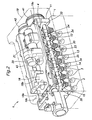
- the engine E (variable valve lift internal combustion engine) shown in Figure 1 consists of a four-stroke, in-line four-cylinder gasoline engine for automobiles, and a cylinder head 1 of this engine comprises a pair of exhaust valves 2 and a pair of intake valves 3 for each cylinder C.
- These valves 2 and 3 are actuated by DOHC four-valve valve actuating system driven by an exhaust camshaft 4 and an intake camshaft 5 (which is omitted from illustration in Figure 2 ).
- an exhaust camshaft 4 Between each exhaust valve 2 and the exhaust camshaft 4 is interposed an exhaust rocker arm 6. Between each intake valve 3 and the intake camshaft 5 is interposed an intake rocker arm 7.
- the exhaust valves 2 and intake valves 3 are normally urged in the closing directions by corresponding valve springs 9 and 10.
- the application of the present invention is not limited to the engine of the illustrated embodiment, and is applicable to all kinds of reciprocating internal combustion engines including, not exclusively, Otto cycle engines, diesel engines as well as single cylinder engines and multiple cylinder engines which may be either in-line or V-type.
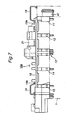
- cam holders 11 to 15 are secured to the upper surface of the cylinder head 1 in a mutually spaced relationship and along the lengthwise direction of the cylinder head 1 to rotatably support the two camshafts 4 and 5 and rocker shafts for the rocket arms 6 and 7.
- the cam holder on the right end as seen in Figure 2 is referred to as the front cam holder 11, the one in the middle as the center cam holder 13, the one the left end as the rear cam holder 15, and the remaining ones as the middle cam holders 12 and 14.
- the center cam holder 13 is bifurcated into a pair of support walls 16 and 17 at the exhaust end thereof, and the axially central part of the exhaust camshaft 4 is supported by these support walls 16 and 17.
- a base plate 18 that covers the valve actuating mechanism in cooperation with a head cover 19.
- the engine E of the illustrated embodiment is equipped with a pair of variable valve timing control (VTC) mechanisms 41 and 42 that variably and continually control the angular phases of the two camshafts 4 and 5, respectively, and a variable valve lift control (VLC) mechanism 20 for variable and continually controlling the lift of the exhaust valve 2 as a part of a variable valve control system.
- VTC variable valve timing control
- VLC variable valve lift control
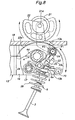
- the VLC mechanism 20 comprises an electric motor (actuator) 21 mounted on the base plate 18 (not shown in Figure 3 ) in parallel with the two camshafts 4 and 5, a sector drive gear 22 attached to an output shaft 2 1 a of the electric motor 21, a gear link (driven gear) 23 consisting of an integral member including a driven gear portion 23a, a pivot arm portion 23c and a shaft holder portion 23b, a control shaft 24 rotatably passed through the shaft holder portion 23b of the gear link 23, a control arm (roller link) 25 provided for each cylinder and having a base end through which the control shaft 24 is rotatably passed, a roller 27 rotatably supported by the free end of each control arm 25 via a roller shaft 26, and a spring unit 28 which normally urges each roller 27 toward the exhaust camshaft 4 or in particular the corresponding cam lobe thereof.
- actuator electric motor
- a sector drive gear 22 attached to an output shaft 2 1 a of the electric motor 21
- a gear link (driven gear) 23
- Numeral 29 in Figures 1 and 2 denote a rotary encoder for detecting the angular position of the drive gear 22, and an engine ECU not shown in the drawings determines the position of the control shaft 24 according to an output signal from the rotary encoder 29 to feedback control the electric current supplied to the electric motor 21.
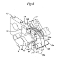
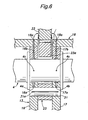
- Figure 5 is a fragmentary perspective view showing the relationship between the center cam holder 13 and gear link 23, and Figure 6 is a sectional view of the center cam holder 13 and gear link 23 at a part where these two components are connected to each other.
- the gear link 23 is rotatably supported at the pivot arm portion 23c thereof by the support walls 16 and 17 of the center cam holder 13 via a support pin 31, and is angularly actuated by the drive gear 22 that meshes with the driven gear portion 23a.
- the two axial ends surfaces of the support pin 31 are engaged by corresponding thrust flanges 4a and 4b formed in the exhaust camshaft 4.
- an oil groove 31a is formed longitudinally on the outer circumferential surface of the support pin 31, and oil holes 16a and 17a are formed in the corresponding support walls 16 and 17 of the center cam holder 13 so that the engine oil fed from an oil hole 4c formed in the exhaust camshaft 4 is supplied to the outer circumferential surface of the support pin 31 via the oil holes 16a and 17a and the oil groove 31a.
- the center cam holder 13 and base plate 18 are also formed with oil holes 16b, 17b and 18a for spouting the engine oil fed from an oil hole 4c formed in the exhaust camshaft 4 upward from the upper surface of the base plate 18 to lubricate the part where the drive gear 22 and the driven gear portion 23a among other places.
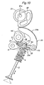
- Figure 8 shows the range of the variable actuation stroke of the VLC mechanism.
- the gear link 23 can turn continuously from a position indicated by the solid lines in Figure 8 (minimum lift position) and a position indicated by broken lines in Figure 8 (maximum lift position), and this angular movement of the gear link 23 causes a rotation of the control shaft 24 (and hence the shaft holder portion 23b) around the support pin 31.
- the vertical end surfaces of the support walls 16 and 17 facing the exhaust side are each provided with an upper stopper portion 13a for limiting an upward angular movement of the shaft holder portion 23b (and hence the gear link 23) and a lower stopper portion 13b for liming a downward angular movement of the shaft holder portion 23b (and hence the gear link 23).
- the range of the angular movement of the gear link 23 is defined not by any separate stopper members but by stopper portions 13a and 13b formed in appropriate parts of the support walls 16 and 17. Because the gear link 23 moves only between the minimum lift position and maximum lift position, the contact between the stopper portions 13a and 13b and the shaft holder portion 23b does not cause any wear to these components. The engagement between the stopper portions 13a and 13b and the shaft holder portion 23b positively prevent any overshooting of the gear link 23 beyond the minimum lift position or maximum lift position.
- the control shaft 24 is rotatably supported not only by the center cam holder 13 via the gear link 23 but also by the remaining cam holders 11, 12, 14 and 15 via a front link holder 33, a pair of middle link holders 34 and a rear link holder 35.
- the front link holder 33 is pivotally supported on an end surface of the front cam holder 11 and the rear link holder 35 is pivotally supported on an end surface of the rear cam holder 15 while each of the middle link holders 34 is pivotally supported by the corresponding middle cam holder 12, 14 via a pair of arms 34b and 34c as illustrated in Figure 3 .
- the ends of the arms 34b and 34c remote from the control shaft 24 are connected to either end of a pin 38, via a C clip 39, which is passed through the corresponding middle cam holder 12, 14. Therefore, the arms 34b and 34c are supported by the corresponding middle cam holder 12, 14 in a symmetric manner.
- the pin 38 is lubricated by the engine oil which is supplied from the middle cam holders 12 and 14 via oil holes (not shown in the drawings) communicating with the exhaust camshaft 4.
- Each of the front cam holder 11, the middle cam holders 12 and 14 and the rear cam holder 15 is provided with an upper stopper portion and a lower stopper portion for limiting the angular movement of the corresponding link holder.
- each the control arm 25 pivots around a minimum lift point P1 when the gear link 23 is at the minimum lift position, and around a maximum lift point P2 when the gear link 23 is at the maximum lift position.
- the roller 27 is interposed between a pair of link arms 25a and 25b forming the control arm 25 and is rotatably supported by the roller shaft 26 around an axial line extending across the link arms 25a and 25b, and engages the cam lobe 4b of the exhaust camshaft 4.
- the roller shaft 26 extends laterally outward from either link arms 25a and 25b, and engages arcuate surfaces 6a formed on the corresponding exhaust rocker arms 6.
- Each arcuate surface 6a has an arc center P3 located upwardly and inwardly with respect to the minimum lift point P1.
- the planar base plate 18 is attached to the upper surfaces of the cam holders 11 to 15 by passing threaded bolts through mounting holes 18b formed in the base plate 18 and threading into the threaded holes of the corresponding cam holders 11 to 15.
- the base plate 18 securely joins the upper parts of the cam holders 11 to 15 with one another so as to reinforce the cam holders 11 to 15 against forces that may tend to tilt the cam holders.
- the base plate 18 additionally serves as a base for supporting the electric motor 21, and a fuel pipe housing 43 accommodating fuel delivery pipes therein. As will be discussed hereinafter, the base plate 18 serves also as a part of the head cover for the cylinder head 1.
- the base plate 18 includes a planar region for supporting the electric motor 21, and threaded holes 18c for securing the head cover 19 are provided in a peripheral part of the base plate 18.
- the head cover 19 is formed with mounting holes 19c, and is attached to the upper part of the cylinder head 1 by passing threaded bolts through these mounting holes 19c and threading them into the threaded holes 18c.
- oil holes 18a and 18b are formed in parts of the base plate 18 adjacent to the center cam holder 18 for upwardly spouting lubricating oil supplied thereto via oil holes 16b and 17b formed in the support walls 16 and 17. This oil lubricates the meshing part between the sector drive gear 22 and the driven gear portion 23a of the gear link 23, and other parts of the gear link 23.
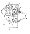
- Figure 4 shows a cross section of the head cover 19
- Figure 7 shows a longitudinal section of the head cover 19.
- the head cover 19 is provided with a central window 19a which overlaps with a central part of the base plate 18, and the peripheral edge of the head cover 19 surrounding the central window 19a is formed as a vertical flange whose free end abuts the upper surface of the outer peripheral part of the base plate 18 via a seal member 19d that is received in a groove 19b extending over the entire length of the vertical flange.
- the seal member 19d partly projects from the groove 19 under an unstressed condition so that the seal member 19d provides a favorable sealing effect in cooperation with the opposing surface by undergoing a resilient deformation.
- the outer peripheral edge of the head cover 19 is also formed as a vertical flange that abuts the outer peripheral part of the top surface of the cylinder head 1 via a similar seal member 19d that is received in a groove 19b extending over the entire length of the vertical flange.
- the valve actuating mechanism is completely enclosed jointly by the head cover 19 and the base plate 18 in an air tight manner.
- the head cover 19 in the illustrated embodiment is generally annular in shape, but may also take other form such as C-shape, L-shape and so on as seen in plan view. Therefore, the central window in such a case would consist of a cutout instead of a fully surrounded opening.
- Figure 9 shows the VLC mechanism at the maximum lift position
- Figure 10 shows the VLC mechanism at the minimum lift position.
- the gear link 23 When the drive gear 22 drives the gear link 23, the meshing between the drive gear 23 and the driven gear portion 23a of the gear link 23 causes a significant reaction that tends to push the two parts away from each other. In particular, the gear link 23 is subjected to a significant downward force. In the illustrated embodiment, because the gear link 23 is supported by the support walls 16 and 17 on either side, and the gear link 23 is located in an axially central part of the exhaust camshaft 4, the gear link 23 and control shaft 24 are favorably supported against tilting and twisting deformations.
- the support pin 31 supporting the gear link 23 is lubricated by the engine oil not only at the journal bearings formed in the support walls 16 and 17 for supporting the support pin 31 but also at the journal bearing formed in the gear link 23 on account of the oil groove 31a formed in the support pin 31.
- the engine oil which is upwardly spouted from the oil holes 18a of the base plate 18 favorably lubricates the meshing part between the drive gear 23 and the driven gear portion 23a and other parts above the base plate 18. Therefore, the various sliding parts of the gear link 23 are favorably lubricated, and are prevented from any undesired wear.
- the exhaust camshaft 4 is supported by the bifurcated support walls 16 and 17 of the central cam holder 13 and is therefore supported over a greater length by the central cam holder 13 than any of the remaining cam holders 11, 12, 14 and 15.
- the resulting increase in the support rigidity of the exhaust camshaft 4 contributes in the reduction in the bending deformation of the exhaust camshaft 4 and the elimination in the variations in the valve lift from one cylinder to another.
- each of the front cam holder 11, the middle cam holders 12 and 14 and the rear cam holder 15 is provided with an upper stopper portion and a lower stopper portion for limiting the angular movement of the corresponding link holder. Therefore, any excessive lifting of the valve can be avoided, and this prevents generation of noises and improper mode of engine operation.
- the cam holders 11 to 15 are subjected to various forces as they support not only the camshafts 4 and 5 and rocket arms 6 and 7, but also the gear link 23 and control shaft 24.
- the base plate 18 connects the upper parts of the cam holders 11 to 15 to one another, the rigidity of the cam holders 11 to 15, in particular the rigidity against the tilting of the cam holders 11 to 15 can be increased. Therefore, the thickness (in the axial direction) of each cam holder can be reduced without any ill effect, and this contributes to a compact design of the engine E.
- a seal member 19d is interposed between the head cover 19 and base plate 18, the base plate 18 is able to fully function as a part of the head cover 19, and leaking of engine oil from the cam chamber can be avoided. Thereby, the head cover 19 may be provided with a central window 19a, and this also contributes to a light-weight design of the engine E.
- the drive gear 22 for transmitting the torque of the electric motor is formed as a sector gear having teeth only over an angular range necessary to mesh with the drive gear portion 23a, instead of a circular gear so that the weight of the drive gear 22 as well as the space requirement for the drive gear can be minimized. This again contributes to a compact and light-weight design of the engine E.
- the present invention has been described in terms of preferred embodiments thereof, it is obvious to a person skilled in the art that various alterations and modifications are possible without departing from the scope of the present invention which is set forth in the appended claims.
- the illustrated embodiments were directed to the in-line four-cylinder DOHC gasoline engine having a variable valve lift mechanism provided only to the exhaust valve actuating mechanism, but the present invention is also applicable to different types engines such as V-cylinder engines, SOHC engines and diesel engines, and to those having a variable valve lift mechanism provided only to or additionally to the intake valve actuating mechanism.
- the speed reduction gear used in the foregoing embodiments essentially consisted of spur gear mechanism, but worm speed reduction mechanisms, chain mechanisms, belt mechanisms and cam mechanisms may also be used.
- the various details of the variable valve lift mechanism can be modified without departing from the spirit of the present invention.
- a variable valve lift internal combustion engine including a control shaft (24) pivotally supported by a cylinder head (1) via a pivot arm (23c) pivotally supported by the cylinder head so as to able to move angularly around a rotational center line extending in parallel with an axial line of the control shaft, a power transmitting member (23a) supporting the control shaft, an actuator (21) for causing an angular movement of the control shaft around the rotational center line via the power transmitting member and a control arm (25) having a base end pivotally supported by the control shaft and a free end interposed between a cam lobe (4d) of an engine camshaft (4) and a part of a rocker arm (6).
- the lift of the engine valve can be varied by angularly moving the control shaft around the rotational center line and moving the base end of the control arm.
Landscapes
- Engineering & Computer Science (AREA)
- Mechanical Engineering (AREA)
- General Engineering & Computer Science (AREA)
- Valve Device For Special Equipments (AREA)
Claims (12)
- Verbrennungsmotor (E) mit variablem Ventilhub, umfassend:ein Motorventil (2);eine Nockenwelle (4), die an einem Zylinderkopf (1) des Motors (E) angebracht ist und eine Nockenerhebung (4d) umfasst;einen Kipphebel (6), der schwenkbar von dem Zylinderkopf (1) gelagert ist und einen ersten Teil umfasst, welcher in einen Ventilstössel des Motorventils eingreift;eine Steuerwelle (24), die vermittels eines schwenkbar von dem Zylinderkopf (1) gelagerten Schwenkhebels (23c) schwenkbar von dem Zylinderkopf (1) gelagert ist, so dass sie dazu in der Lage ist, eine Winkel-Bewegung um eine Rotations-Mittellinie auszuführen, welche sich parallel zu einer axialen Linie der Steuerwelle (24 ) erstreckt;ein Kraftübertragungselement (23a), das die Steuerwelle (24) lagert;einen Aktuator (21), um eine Winkel-Bewegung der Steuerwelle (24) um die Rotations-Mittellinie vermittels des Kraftübertragungselements (23a) zu bewirken; undeinen Steuerhebel (25), der ein Basis-Ende aufweist, welches schwenkbar von der Steuerwelle (24) gelagert ist und ein freies Ende, das zwischen der Nockenerhebung (4d) und einem zweiten Teil des Kipphebels (6) angeordnet ist;wobei ein Hub des Motorventils (2) variiert wird, indem die Steuerwelle (24) eine Winkel-Bewegung um die Rotations-Mittellinie ausführt und das Basis-Ende des Steuerhebels (25) bewegt wird, wobei das Basis-Ende des Schwenkhebels (23c) schwenkbar von einem Nockenhalter (13) gelagert ist,
gekennzeichnet dadurch, dass der Nockenhalter (13), der das Basis-Ende des Schwenkhebels (23) lagert, zentral entlang einer Länge der Steuerwelle (24) angeordnet ist. - Verbrennungsmotor (E) mit variablem Ventilhub nach Anspruch 1,
wobei der Schwenkhebel (23c) und das Kraftübertragungselement (23a) durch ein integrales Verbindungselement (23) gebildet sind, welches einen Schwenkhebelabschnitt (23c) umfasst, der schwenkbar von dem Zylinderkopf gelagert ist, einen Lagerabschnitt (23b), der schwenkbar die Steuerwelle (24) lagert und einen Kraftübertragungsabschnitt (23a), der sich von dem Lagerabschnitt (23b) aus erstreckt und in ein Ausgabe-Ende des Aktuators (21) eingreift. - Verbrennungsmotor (E) mit variablem Ventilhub nach Anspruch 2,
wobei der Kraftübertragungsabschnitt (23a) des integralen Verbindungselements (23) einen Abtriebszahnradabschnitt (23a) umfasst, der mit einem Antriebszahnrad (22) des Aktuators (21) in Eingriff steht. - Verbrennungsmotor (E) mit variablem Ventilhub nach einem der Ansprüche 1 bis 3,
wobei das Basis-Ende des Schwenkhebels (23c) schwenkbar von einem Gelenkzapfen (31) gelagert ist, der teilweise in eine Lagerbohrung des Nockenhalters (13) eingesetzt ist, wobei der Nockenhalter (13) ein Öl-Loch (16a, 17a) umfasst, um der Lagerbohrung Schmieröl zuzuführen. - Verbrennungsmotor (E) mit variablem Ventilhub nach Anspruch 4,
wobei der Nockenhalter (13) ein Paar von gegabelten Halterungswänden (16, 17) umfasst, und der Gelenkzapfen (31) durch die Halterungswände (16, 17) hindurch geführt ist, wobei das Basis-Ende des Schwenkhebels (23c) mit einer Lagerbohrung ausgebildet ist, durch welche ein Zwischenteil des Gelenkzapfens (31) hindurch verläuft. - Verbrennungsmotor (E) mit variablem Ventilhub nach Anspruch 5,
wobei der Gelenkzapfen (31) mit einer axialen Öl-Nut (31 a) ausgebildet ist, um Schmieröl zu der in dem Basis-Ende des Schwenkhebels (23c) ausgebildeten Lagerbohrung zu leiten. - Verbrennungsmotor (E) mit variablem Ventilhub nach einem der Ansprüche 1 bis 6,
wobei der Nockenhalter (13) mit Anschlagsabschnitten (13a, 13b) versehen ist, um einen Bereich einer Winkel-Bewegung der Steuerwelle (24) zu begrenzen. - Verbrennungsmotor (E) mit variablem Ventilhub nach einem der Ansprüche 1 bis 7,
wobei der Motor (E) eine Mehrzahl von Nockenhaltern (11-15) umfasst, die entlang der Rotations-Mittellinie angeordnet sind, und eine Grundplatte (18) umfasst, die obere Enden der Nockenhalter (11-15) miteinander verbindet. - Verbrennungsmotor (E) mit variablem Ventilhub nach Anspruch 8,
weiter umfassend eine Kopf-Abdeckung (19), die einen an einem Zylinderkopf (1) des Motors (E) vorgesehenen Ventil-Betätigungs-Mechanismus zusammen mit der Grundplatte (18) abdeckt, wobei die Kopf-Abdeckung (19) einen Rand umfasst, der an einer Fläche der Grundplatte (18) vermittels eines Dichtungselements (19d) anliegt. - Verbrennungsmotor (E) mit variablem Ventilhub nach Anspruch 9,
wobei die Kopf-Abdeckung (19) mit einer ringförmigen Anordnung versehen ist, welche ein zentrales Fenster (19a) umfasst, und ein Umfangsrand der Kopf-Abdeckung (19), der das zentrale Fenster (19a) umgibt, an einer Fläche der Grundplatte vermittels eines Dichtungselements (19d) anliegt. - Verbrennungsmotor (E) mit variablem Ventilhub nach Anspruch 3,
wobei das Antriebszahnrad (22) ein Segment-Zahnrad umfasst. - Verbrennungsmotor (E) mit variablem Ventilhub nach Anspruch 3,
wobei das Kraftübertragungselement (23a) des integralen Verbindungselements (23) einen Abtriebszahnrad-Abschnitt (23a) umfasst, der mit einem Antriebzahnrad (22) des Aktuators (21) in Eingriff steht, und ein Öl-Loch (16a, 17a) in dem Nockenhalter (13) vorgesehen ist, um Schmieröl zu einem Teil zuzuführen, wo der Abtriebszahnrad-Abschnitt (23a) mit dem Antriebzahnrad (22) in Eingriff steht.
Applications Claiming Priority (3)
| Application Number | Priority Date | Filing Date | Title |
|---|---|---|---|
| JP2006258275A JP4555270B2 (ja) | 2006-09-25 | 2006-09-25 | 開弁特性可変型内燃機関 |
| JP2006258331A JP4563364B2 (ja) | 2006-09-25 | 2006-09-25 | 開弁特性可変型内燃機関 |
| JP2006262222A JP4596568B2 (ja) | 2006-09-27 | 2006-09-27 | 開弁特性可変型内燃機関 |
Publications (2)
| Publication Number | Publication Date |
|---|---|
| EP1905967A1 EP1905967A1 (de) | 2008-04-02 |
| EP1905967B1 true EP1905967B1 (de) | 2009-12-16 |
Family
ID=38805649
Family Applications (1)
| Application Number | Title | Priority Date | Filing Date |
|---|---|---|---|
| EP07017795A Expired - Fee Related EP1905967B1 (de) | 2006-09-25 | 2007-09-11 | Verbrennungsmotor mit variabler Ventilhebung |
Country Status (3)
| Country | Link |
|---|---|
| US (1) | US7669564B2 (de) |
| EP (1) | EP1905967B1 (de) |
| DE (1) | DE602007003789D1 (de) |
Families Citing this family (31)
| Publication number | Priority date | Publication date | Assignee | Title |
|---|---|---|---|---|
| JP4878594B2 (ja) * | 2007-11-13 | 2012-02-15 | 日立オートモティブシステムズ株式会社 | 内燃機関の可変動弁装置 |
| US20090283062A1 (en) * | 2008-05-14 | 2009-11-19 | Elias Taye | Actuator with self-locking helical gears for a continuously variable valve lift system |
| US9016252B2 (en) | 2008-07-22 | 2015-04-28 | Eaton Corporation | System to diagnose variable valve actuation malfunctions by monitoring fluid pressure in a hydraulic lash adjuster gallery |
| US9938865B2 (en) | 2008-07-22 | 2018-04-10 | Eaton Corporation | Development of a switching roller finger follower for cylinder deactivation in internal combustion engines |
| US9291075B2 (en) | 2008-07-22 | 2016-03-22 | Eaton Corporation | System to diagnose variable valve actuation malfunctions by monitoring fluid pressure in a control gallery |
| US9228454B2 (en) | 2010-03-19 | 2016-01-05 | Eaton Coporation | Systems, methods and devices for rocker arm position sensing |
| US8985074B2 (en) | 2010-03-19 | 2015-03-24 | Eaton Corporation | Sensing and control of a variable valve actuation system |
| US9284859B2 (en) | 2010-03-19 | 2016-03-15 | Eaton Corporation | Systems, methods, and devices for valve stem position sensing |
| US20190309663A9 (en) | 2008-07-22 | 2019-10-10 | Eaton Corporation | Development of a switching roller finger follower for cylinder deactivation in internal combustion engines |
| US9581058B2 (en) | 2010-08-13 | 2017-02-28 | Eaton Corporation | Development of a switching roller finger follower for cylinder deactivation in internal combustion engines |
| US9708942B2 (en) | 2010-03-19 | 2017-07-18 | Eaton Corporation | Rocker arm assembly and components therefor |
| US9038586B2 (en) | 2010-03-19 | 2015-05-26 | Eaton Corporation | Rocker assembly having improved durability |
| US10415439B2 (en) | 2008-07-22 | 2019-09-17 | Eaton Intelligent Power Limited | Development of a switching roller finger follower for cylinder deactivation in internal combustion engines |
| JP5066504B2 (ja) * | 2008-09-30 | 2012-11-07 | 本田技研工業株式会社 | 可変動弁装置を備えた内燃機関及び自動二輪車 |
| JP5113005B2 (ja) * | 2008-09-30 | 2013-01-09 | 本田技研工業株式会社 | 可変動弁装置を備えた内燃機関 |
| JP5115747B2 (ja) * | 2009-02-13 | 2013-01-09 | スズキ株式会社 | 内燃機関の可変動弁装置 |
| US10087790B2 (en) | 2009-07-22 | 2018-10-02 | Eaton Corporation | Cylinder head arrangement for variable valve actuation rocker arm assemblies |
| US11181013B2 (en) | 2009-07-22 | 2021-11-23 | Eaton Intelligent Power Limited | Cylinder head arrangement for variable valve actuation rocker arm assemblies |
| US9194261B2 (en) | 2011-03-18 | 2015-11-24 | Eaton Corporation | Custom VVA rocker arms for left hand and right hand orientations |
| US9874122B2 (en) | 2010-03-19 | 2018-01-23 | Eaton Corporation | Rocker assembly having improved durability |
| US9885258B2 (en) | 2010-03-19 | 2018-02-06 | Eaton Corporation | Latch interface for a valve actuating device |
| US8955478B2 (en) * | 2010-11-08 | 2015-02-17 | Toyota Jidosha Kabushiki Kaisha | Variable valve operating apparatus |
| CN102554854B (zh) * | 2012-02-08 | 2014-09-03 | 重庆小康工业集团股份有限公司 | 一种柴油发动机主从动齿轮装配止动装置 |
| USD750670S1 (en) | 2013-02-22 | 2016-03-01 | Eaton Corporation | Rocker arm |
| EP3502451B1 (de) * | 2013-04-12 | 2021-11-10 | Eaton Intelligent Power Limited | Zylinderkopfanordnung für kipphebelanordnungen zur variablen ventilbetätigung |
| CN103334807B (zh) * | 2013-06-03 | 2016-01-20 | 浙江亿日气动科技有限公司 | 带驱动轴的电动发动机制动执行装置 |
| DE112015000034T5 (de) | 2014-03-03 | 2015-11-19 | Eaton Corporation | Ventilbetätigungsvorrichtung und Verfahren zu deren Herstellung |
| DE102014210477A1 (de) * | 2014-06-03 | 2015-12-03 | Schaeffler Technologies AG & Co. KG | Trägermodul |
| KR101646135B1 (ko) * | 2015-06-22 | 2016-08-05 | 현대자동차 주식회사 | 연속 가변 밸브 리프트 장치 및 이를 포함하는 엔진 |
| DE102016004531A1 (de) * | 2016-04-13 | 2017-10-19 | Man Truck & Bus Ag | Variabler Ventiltrieb mit einem Kipphebel |
| EP3623592A1 (de) * | 2018-09-17 | 2020-03-18 | Uwe Eisenbeis | Variabler ventiltrieb mit schmiermittelversorgungssystem |
Family Cites Families (8)
| Publication number | Priority date | Publication date | Assignee | Title |
|---|---|---|---|---|
| JP3092390B2 (ja) * | 1993-04-28 | 2000-09-25 | トヨタ自動車株式会社 | 内燃機関の可変動弁機構 |
| DE19960742B4 (de) * | 1999-12-16 | 2006-09-28 | Iav Gmbh Ingenieurgesellschaft Auto Und Verkehr | Variabler Ventiltrieb, vorzugsweise für Verbrennungsmotoren |
| DE10123186A1 (de) | 2001-05-12 | 2002-11-14 | Bayerische Motoren Werke Ag | Ventiltrieb-Vorrichtung zur variablen Hubverstellung eines Gaswechselventils einer Brennkraftmaschine |
| DE10125082A1 (de) | 2001-05-23 | 2002-11-28 | Bayerische Motoren Werke Ag | Ventiltrieb-Vorrichtung für eine Brennkraftmaschine |
| JP2004239249A (ja) * | 2003-02-03 | 2004-08-26 | Zenji Ishikawa | 内燃機関の動弁機構 |
| JP4192807B2 (ja) | 2004-03-05 | 2008-12-10 | トヨタ自動車株式会社 | 可変動弁システム |
| JP2005307965A (ja) * | 2004-03-24 | 2005-11-04 | Honda Motor Co Ltd | エンジンの制振構造 |
| JP4251364B2 (ja) * | 2004-06-04 | 2009-04-08 | 善司 石川 | 4サイクル内燃機関の動弁機構 |
-
2007
- 2007-09-11 EP EP07017795A patent/EP1905967B1/de not_active Expired - Fee Related
- 2007-09-11 DE DE602007003789T patent/DE602007003789D1/de active Active
- 2007-09-21 US US11/902,406 patent/US7669564B2/en not_active Expired - Fee Related
Also Published As
| Publication number | Publication date |
|---|---|
| US7669564B2 (en) | 2010-03-02 |
| DE602007003789D1 (de) | 2010-01-28 |
| US20080072854A1 (en) | 2008-03-27 |
| EP1905967A1 (de) | 2008-04-02 |
Similar Documents
| Publication | Publication Date | Title |
|---|---|---|
| EP1905967B1 (de) | Verbrennungsmotor mit variabler Ventilhebung | |
| US7469669B2 (en) | Variable valve train mechanism of internal combustion engine | |
| US7588003B2 (en) | Valve train for internal combustion engine | |
| EP1598530A1 (de) | Baueinheit von einer Vielzahl von Distanzhülsen und variablen Ventiltriebmechanismen auf einer Welle | |
| US7305946B2 (en) | Variable valve operating apparatus for internal combustion engine | |
| CN101255808B (zh) | 具有轴装式凸轮从动件的发动机/气门机构 | |
| US7073470B2 (en) | Variable valve apparatus of internal combustion engine | |
| US7934476B2 (en) | Valve-actuating system for an internal combustion engine, engine incorporating same, and method of using same | |
| CN100396888C (zh) | 内燃机的气门传动装置 | |
| US8667936B2 (en) | Valve control apparatus for internal combustion engine | |
| JP4762963B2 (ja) | 開弁特性可変型内燃機関 | |
| CN100396889C (zh) | 内燃机的气门传动装置 | |
| US7290511B2 (en) | Valve train for internal combustion engine | |
| US8794204B2 (en) | Valvetrain for overhead valve engine | |
| JP4179101B2 (ja) | エンジンの可変動弁装置 | |
| US7789053B2 (en) | Continuous variable valve lift apparatus | |
| JP4860669B2 (ja) | 内燃機関の可変動弁装置 | |
| JP4555270B2 (ja) | 開弁特性可変型内燃機関 | |
| US20130019831A1 (en) | Valve actuation apparatus of internal combustion engine | |
| JP4481294B2 (ja) | 開弁特性可変型内燃機関 | |
| JP4563364B2 (ja) | 開弁特性可変型内燃機関 | |
| US7469668B2 (en) | Valve-moving device for engine | |
| JP4596568B2 (ja) | 開弁特性可変型内燃機関 | |
| JP4103579B2 (ja) | エンジンの可変動弁装置 | |
| JP2009264140A (ja) | 開弁特性可変型内燃機関 |
Legal Events
| Date | Code | Title | Description |
|---|---|---|---|
| PUAI | Public reference made under article 153(3) epc to a published international application that has entered the european phase |
Free format text: ORIGINAL CODE: 0009012 |
|
| 17P | Request for examination filed |
Effective date: 20070911 |
|
| AK | Designated contracting states |
Kind code of ref document: A1 Designated state(s): AT BE BG CH CY CZ DE DK EE ES FI FR GB GR HU IE IS IT LI LT LU LV MC MT NL PL PT RO SE SI SK TR |
|
| AX | Request for extension of the european patent |
Extension state: AL BA HR MK YU |
|
| 17Q | First examination report despatched |
Effective date: 20080617 |
|
| AKX | Designation fees paid |
Designated state(s): DE FR GB |
|
| GRAP | Despatch of communication of intention to grant a patent |
Free format text: ORIGINAL CODE: EPIDOSNIGR1 |
|
| GRAS | Grant fee paid |
Free format text: ORIGINAL CODE: EPIDOSNIGR3 |
|
| GRAA | (expected) grant |
Free format text: ORIGINAL CODE: 0009210 |
|
| AK | Designated contracting states |
Kind code of ref document: B1 Designated state(s): DE FR GB |
|
| REG | Reference to a national code |
Ref country code: GB Ref legal event code: FG4D |
|
| REF | Corresponds to: |
Ref document number: 602007003789 Country of ref document: DE Date of ref document: 20100128 Kind code of ref document: P |
|
| PLBE | No opposition filed within time limit |
Free format text: ORIGINAL CODE: 0009261 |
|
| STAA | Information on the status of an ep patent application or granted ep patent |
Free format text: STATUS: NO OPPOSITION FILED WITHIN TIME LIMIT |
|
| 26N | No opposition filed |
Effective date: 20100917 |
|
| PGFP | Annual fee paid to national office [announced via postgrant information from national office to epo] |
Ref country code: FR Payment date: 20100921 Year of fee payment: 4 |
|
| PGFP | Annual fee paid to national office [announced via postgrant information from national office to epo] |
Ref country code: DE Payment date: 20100908 Year of fee payment: 4 |
|
| GBPC | Gb: european patent ceased through non-payment of renewal fee |
Effective date: 20110911 |
|
| REG | Reference to a national code |
Ref country code: FR Ref legal event code: ST Effective date: 20120531 |
|
| REG | Reference to a national code |
Ref country code: DE Ref legal event code: R119 Ref document number: 602007003789 Country of ref document: DE Effective date: 20120403 |
|
| PG25 | Lapsed in a contracting state [announced via postgrant information from national office to epo] |
Ref country code: DE Free format text: LAPSE BECAUSE OF NON-PAYMENT OF DUE FEES Effective date: 20120403 |
|
| PG25 | Lapsed in a contracting state [announced via postgrant information from national office to epo] |
Ref country code: FR Free format text: LAPSE BECAUSE OF NON-PAYMENT OF DUE FEES Effective date: 20110930 Ref country code: GB Free format text: LAPSE BECAUSE OF NON-PAYMENT OF DUE FEES Effective date: 20110911 |