EP1903589A2 - Sectionneur à coupure en charge de sécurité doté d'une boîte d'extinction d'arc - Google Patents
Sectionneur à coupure en charge de sécurité doté d'une boîte d'extinction d'arc Download PDFInfo
- Publication number
- EP1903589A2 EP1903589A2 EP07115175A EP07115175A EP1903589A2 EP 1903589 A2 EP1903589 A2 EP 1903589A2 EP 07115175 A EP07115175 A EP 07115175A EP 07115175 A EP07115175 A EP 07115175A EP 1903589 A2 EP1903589 A2 EP 1903589A2
- Authority
- EP
- European Patent Office
- Prior art keywords
- switch
- fuse
- arc chamber
- fixed contact
- slots
- Prior art date
- Legal status (The legal status is an assumption and is not a legal conclusion. Google has not performed a legal analysis and makes no representation as to the accuracy of the status listed.)
- Granted
Links
Images


Classifications
-
- H—ELECTRICITY
- H01—ELECTRIC ELEMENTS
- H01H—ELECTRIC SWITCHES; RELAYS; SELECTORS; EMERGENCY PROTECTIVE DEVICES
- H01H9/00—Details of switching devices, not covered by groups H01H1/00 - H01H7/00
- H01H9/30—Means for extinguishing or preventing arc between current-carrying parts
- H01H9/34—Stationary parts for restricting or subdividing the arc, e.g. barrier plate
- H01H9/342—Venting arrangements for arc chutes
-
- H—ELECTRICITY
- H01—ELECTRIC ELEMENTS
- H01H—ELECTRIC SWITCHES; RELAYS; SELECTORS; EMERGENCY PROTECTIVE DEVICES
- H01H31/00—Air-break switches for high tension without arc-extinguishing or arc-preventing means
- H01H31/02—Details
- H01H31/12—Adaptation for built-in fuse
- H01H31/122—Fuses mounted on, or constituting the movable contact parts of, the switch
-
- H—ELECTRICITY
- H01—ELECTRIC ELEMENTS
- H01H—ELECTRIC SWITCHES; RELAYS; SELECTORS; EMERGENCY PROTECTIVE DEVICES
- H01H9/00—Details of switching devices, not covered by groups H01H1/00 - H01H7/00
- H01H9/30—Means for extinguishing or preventing arc between current-carrying parts
- H01H9/34—Stationary parts for restricting or subdividing the arc, e.g. barrier plate
Definitions
- the invention relates to a fuse switch disconnector with at least one fixedly arranged on the switch fixed contact part with which a pivotable on a handle portion arranged on the fuse switch disconnectors contact is contacted and at least one hollow arc chamber whose interior is divided into three subspaces, wherein the arc chamber in Switch opening direction is arranged above each one fixed contact part of a switching phase of the fuse switch-disconnector, so that when the switch opening the contact blade enters the arc chamber.
- a generic fuse switch-disconnector is known from German Utility Model G 92 08 693.4.
- This fuse switch disconnector consists of a base with the receptacle contacts for the blades of low-voltage high-performance fuses.
- the low-voltage high-performance fuses are held in a fuse holder via retaining lugs.
- the fuse holder is connected to the lower part via a swivel joint.
- the receptacle contacts are covered by a cover. Slots for inserting the knives are inserted in the cover.
- the cover is equipped with an outwardly closed, slot-shaped arc guide having an outlet opening.
- the fuse switch disconnector When the fuse switch disconnector is opened, the fuse holder is disconnected from the base by pulling the contact blades out of the receptacle contacts while moving the fuse holder. The resulting arc enters the slot-shaped arc guide. One part emerges from the outlet opening, another part is deflected into Lichtbogenumlenkwaitn.
- the invention has for its object to provide a fuse switch disconnectors available that ensures a high switching capacity while reducing a risk of short circuit in a simple structural design.
- a fuse switch disconnector with at least one fixed contact part fixedly arranged on the switch is provided, with which a contact blade arranged pivotably on a handle part on the fuse switch disconnector can be contacted.
- the fuse switch-disconnector has at least one hollow arc chamber, the interior of which is subdivided into three subspaces, wherein the arc chamber is arranged in the switch opening direction above a respective fixed contact part of a switching phase of the fuse switch disconnector, so that at switch opening the Contact blade enters the arc chamber.
- Each of the three subspaces has at least one slot in one of its outer walls.
- a fuse switch-disconnector with three phases to be switched thus three chambers are provided, each having three slots for venting.
- a fuse switch-disconnector with three phases to be switched thus has a total of nine ventilation slots.
- the arc chamber is arranged on the lower part, that is to say the contact blade on the grip part passes through the arc chamber.
- the arc chamber can have a slot on the side opposite the ventilation slots or on its upper side, through which a respective contact blade arranged on the handle part can be passed.
- the gases are controlled discharged into the environment. This ensures that the concentration of gases within the chamber and outside the chamber is in each case so large that a short circuit is avoided inside and outside the chamber and a user is not exposed to excessive concentration of vapors.
- these slots also cause a directional specification of the outflowing gases, so that they do not hit adjacent contacts. This makes it possible that the distances between the individual phase contacts and thus also the outer dimensions of the fuse switch-disconnector can be kept low.
- the slots extend parallel to the orientation of the respective fixed contact part. That is, when arranged perpendicular to the lower part fixed contact parts, the slots in the outer walls of the subspaces of the arc chamber also perpendicular to the lower part or to its cover.
- the arc chamber advantageously comprises a main space running in alignment with the fixed contact part and two adjoining side rooms, which laterally adjoin the main space, which form the deflection chambers.
- the main room is centrally located between the two side rooms.
- this has an opening in the lower region of the main chamber, which preferably has the shape of a slot adapted to the contour of the contact blade.
- the two adjacent side rooms are closed in the direction of the fixed contact part.
- the central main chamber is open towards the bottom, preferably in the form of a slot, in order to be able to pass the contact blade into and through the arc chamber.
- the two, the main chamber sibling, lateral deflection chambers are closed at the bottom.
- the two adjacent side rooms are open in the direction of the fixed contact part.
- the main chamber is completely open towards the bottom and the two chambers formed as deflection chambers are also open towards the bottom.
- This constructive simple design causes a reduction in manufacturing costs and an additional gas removal option from the secondary chambers. The gases can thus escape from the said slots of the subspaces and flow out downwards.
- the slots are arranged in the wall of the arc chamber, which faces away from the contact blade.
- separating walls for the directed discharge of gases are arranged between the individual arc chambers. These partitions, together with the slots which determine the outflow direction of the gases from the arc chamber, a targeted discharge of the gases in such a way that they can not flow from the contact of a phase to contact an adjacent phase and thus allow arcing.
- the fuse switch-disconnector on a cover, in which the arc chambers of each phase are integrated.
- This cover is preferably detachably connected to the fixed contact part having switch part, so the lower part of the fuse switch disconnector.
- the arc chambers and their slots are arranged such that in the closed switch position, the slots are covered by the handle and only after a pivotal movement of the handle in a position in which the contacts are open, are exposed , That means, that the slots do not extend over the entire height of a wall of a subspace of the arc chamber, but substantially at the upper end, that is, close to the arc chamber upwardly delimiting wall, are arranged.
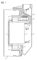
- the fuse switch disconnector shown in the drawings consists of the lower part 1 with the fixed contact parts 2 for the contact blades 3 of the fuses 4.
- the fuses 4 are held in a grip part 5 on the retaining lugs 6.
- the handle part 5 is connected to the lower part 1 via a not-shown known rotary joint.
- the fixed contact parts 2 are covered by a cover 7.
- slots 8 are introduced for insertion of the contact blades 3.
- the cover 7 is equipped with an arc chamber 9.
- the arc chamber 9 has ventilation slots 10.
- a main space 91 and adjacent auxiliary spaces 92 are provided as Lichtbogenumlenkwaitn, in which a part of the resulting arc or its gases can be deflected and thus contribute to the proper arc extinguishing.
- the handle 5 is located with an area in front of the slots 10. They are only after significant opening of the circuit breaker to the free Outlet of the gases released.
- 7 partition walls 15 are provided on the outside of the cover, which flank the outlet opening 10 laterally.
- FIG. 3 three arc chambers 9 are shown in the perspective view of the cover 7 and the lower part 1.
- the arc chambers 9 are separated from each other by a respective partition wall 15.
- Each of the arc chambers 9 has on one side a slot 8 for the passage of the contact blade 3.
- the arc chamber additionally has three vertically arranged ventilation slots 10.
- Each of these three slots 10 is in each case assigned to a partial interior 91, 92 of the arc chamber.
Landscapes
- Arc-Extinguishing Devices That Are Switches (AREA)
Applications Claiming Priority (1)
| Application Number | Priority Date | Filing Date | Title |
|---|---|---|---|
| DE102006044658 | 2006-09-21 |
Publications (3)
| Publication Number | Publication Date |
|---|---|
| EP1903589A2 true EP1903589A2 (fr) | 2008-03-26 |
| EP1903589A3 EP1903589A3 (fr) | 2009-01-14 |
| EP1903589B1 EP1903589B1 (fr) | 2014-10-01 |
Family
ID=38562918
Family Applications (1)
| Application Number | Title | Priority Date | Filing Date |
|---|---|---|---|
| EP20070115175 Not-in-force EP1903589B1 (fr) | 2006-09-21 | 2007-08-29 | Sectionneur à coupure en charge de sécurité doté d'une boîte d'extinction d'arc |
Country Status (1)
| Country | Link |
|---|---|
| EP (1) | EP1903589B1 (fr) |
Cited By (1)
| Publication number | Priority date | Publication date | Assignee | Title |
|---|---|---|---|---|
| DE102007044390B3 (de) * | 2007-09-18 | 2009-02-26 | Wöhner GmbH & Co. KG Elektrotechnische Systeme | Sicherungslasttrennschalter mit doppeltem Berührungsschutz für veränderbare Anschlussrichtung |
Citations (1)
| Publication number | Priority date | Publication date | Assignee | Title |
|---|---|---|---|---|
| EP1302957A1 (fr) | 2001-10-11 | 2003-04-16 | Weber Ag | Dispositif de contact haute puissance basse tension |
Family Cites Families (5)
| Publication number | Priority date | Publication date | Assignee | Title |
|---|---|---|---|---|
| DE1301383B (de) * | 1966-06-16 | 1969-08-21 | Schneider Schaltgeraete | Messertrennschalter, insbesondere Sicherungstrennschalter, mit Schutzabdeckung |
| DE9208693U1 (de) * | 1992-06-29 | 1993-10-28 | Siemens AG, 80333 München | Sicherungstrennschalter |
| DE9404155U1 (de) * | 1994-03-11 | 1994-04-28 | Siemens AG, 80333 München | Sicherungstrennschalter |
| DE29804247U1 (de) * | 1998-03-10 | 1998-05-07 | Siemens AG, 80333 München | Sicherungstrennschalter |
| DE20316027U1 (de) * | 2003-10-18 | 2004-01-15 | Moeller Gmbh | Elektrisches Schaltgerät mit Einrichtung zur Lichtbogenlöschung |
-
2007
- 2007-08-29 EP EP20070115175 patent/EP1903589B1/fr not_active Not-in-force
Patent Citations (1)
| Publication number | Priority date | Publication date | Assignee | Title |
|---|---|---|---|---|
| EP1302957A1 (fr) | 2001-10-11 | 2003-04-16 | Weber Ag | Dispositif de contact haute puissance basse tension |
Cited By (1)
| Publication number | Priority date | Publication date | Assignee | Title |
|---|---|---|---|---|
| DE102007044390B3 (de) * | 2007-09-18 | 2009-02-26 | Wöhner GmbH & Co. KG Elektrotechnische Systeme | Sicherungslasttrennschalter mit doppeltem Berührungsschutz für veränderbare Anschlussrichtung |
Also Published As
| Publication number | Publication date |
|---|---|
| EP1903589A3 (fr) | 2009-01-14 |
| EP1903589B1 (fr) | 2014-10-01 |
Similar Documents
| Publication | Publication Date | Title |
|---|---|---|
| DE4410108C2 (de) | Lichtbogenlöschkammer mit drei Barrieren für den Durchtritt von Lichtbogengasen | |
| EP3111459B1 (fr) | Chambre d'extinction pour un contacteur et contacteur pour l'extinction d'arcs | |
| EP0720772B1 (fr) | Sectionneur de puissance pourvu d'un systeme d'extinction d'arc electrique | |
| DE102009056190B3 (de) | Lichtbogenlöscheinrichtung und Schaltgerät | |
| DE3619241C2 (de) | Löscheinrichtung für einen Leitungsschutzschalter | |
| DE102007058216A1 (de) | Lichtbogen-Löscheinrichtung für einen elektrischen Schalter | |
| EP1903589B1 (fr) | Sectionneur à coupure en charge de sécurité doté d'une boîte d'extinction d'arc | |
| EP0617836B1 (fr) | Coupe-circuit automatique comportant une boite d'extinction d'arc | |
| DE3908102A1 (de) | Selbstschalter, insbesondere leitungsschutzschalter | |
| EP0959483B1 (fr) | Sectionneur de coupure en charge avec une chambre d'extinction | |
| EP1302957A1 (fr) | Dispositif de contact haute puissance basse tension | |
| DE102007001802B4 (de) | Elektrisches Schaltgerät | |
| DE1805354B2 (de) | Stromkreisleiste | |
| DE602005005142T2 (de) | Elektrische Schaltvorrichtung und Lichtbogenlöschkammer mit Deionisierungsflügeln | |
| EP0013289B1 (fr) | Chambre d'extinction plate pour un sectionneur sous charge | |
| DE202005019323U1 (de) | Lichtbogen-Löschkammer des Überstromselbstschalters | |
| DE1690463B1 (de) | Lichtbogenloescheinrichtung fuer elektrische niederspannungs leistungsschalter | |
| DE3810978A1 (de) | Schaltgeraetekombination aus niederspannungs-leistungsschalter und strombegrenzender schalteinrichtung | |
| EP0231733A2 (fr) | Chambre d'extinction d'arc | |
| EP0681737B1 (fr) | Paquet de plaques d'extinction pour une chambre d'extinction d'arc | |
| DE4243537A1 (de) | Verfahren zum Schalten eines Sicherungslasttrenners und Sicherungslasttrenner hierzu | |
| EP0673048B1 (fr) | Dispositif d'extinction d'arc à tÔles d'extinction | |
| DE1149428B (de) | Elektrischer Leistungsschalter | |
| DE2257660A1 (de) | Sicherungsleisten an sammelschienen | |
| DE2640373A1 (de) | Hochspannungs-schaltgeraet |
Legal Events
| Date | Code | Title | Description |
|---|---|---|---|
| PUAI | Public reference made under article 153(3) epc to a published international application that has entered the european phase |
Free format text: ORIGINAL CODE: 0009012 |
|
| AK | Designated contracting states |
Kind code of ref document: A2 Designated state(s): AT BE BG CH CY CZ DE DK EE ES FI FR GB GR HU IE IS IT LI LT LU LV MC MT NL PL PT RO SE SI SK TR |
|
| AX | Request for extension of the european patent |
Extension state: AL BA HR MK YU |
|
| PUAL | Search report despatched |
Free format text: ORIGINAL CODE: 0009013 |
|
| AK | Designated contracting states |
Kind code of ref document: A3 Designated state(s): AT BE BG CH CY CZ DE DK EE ES FI FR GB GR HU IE IS IT LI LT LU LV MC MT NL PL PT RO SE SI SK TR |
|
| AX | Request for extension of the european patent |
Extension state: AL BA HR MK RS |
|
| 17P | Request for examination filed |
Effective date: 20090619 |
|
| 17Q | First examination report despatched |
Effective date: 20090717 |
|
| AKX | Designation fees paid |
Designated state(s): AT BE BG CH CY CZ DE DK EE ES FI FR GB GR HU IE IS IT LI LT LU LV MC MT NL PL PT RO SE SI SK TR |
|
| RAP1 | Party data changed (applicant data changed or rights of an application transferred) |
Owner name: SIEMENS AKTIENGESELLSCHAFT |
|
| GRAP | Despatch of communication of intention to grant a patent |
Free format text: ORIGINAL CODE: EPIDOSNIGR1 |
|
| INTG | Intention to grant announced |
Effective date: 20140428 |
|
| RIN1 | Information on inventor provided before grant (corrected) |
Inventor name: STANG, ALFRED Inventor name: SCUDLO, STEFFEN Inventor name: BLAIMER, GERHARD |
|
| GRAS | Grant fee paid |
Free format text: ORIGINAL CODE: EPIDOSNIGR3 |
|
| GRAA | (expected) grant |
Free format text: ORIGINAL CODE: 0009210 |
|
| AK | Designated contracting states |
Kind code of ref document: B1 Designated state(s): AT BE BG CH CY CZ DE DK EE ES FI FR GB GR HU IE IS IT LI LT LU LV MC MT NL PL PT RO SE SI SK TR |
|
| REG | Reference to a national code |
Ref country code: GB Ref legal event code: FG4D Free format text: NOT ENGLISH |
|
| REG | Reference to a national code |
Ref country code: AT Ref legal event code: REF Ref document number: 689881 Country of ref document: AT Kind code of ref document: T Effective date: 20141015 Ref country code: CH Ref legal event code: EP |
|
| REG | Reference to a national code |
Ref country code: IE Ref legal event code: FG4D Free format text: LANGUAGE OF EP DOCUMENT: GERMAN |
|
| REG | Reference to a national code |
Ref country code: DE Ref legal event code: R096 Ref document number: 502007013490 Country of ref document: DE Effective date: 20141113 |
|
| REG | Reference to a national code |
Ref country code: NL Ref legal event code: VDEP Effective date: 20141001 |
|
| REG | Reference to a national code |
Ref country code: LT Ref legal event code: MG4D |
|
| PG25 | Lapsed in a contracting state [announced via postgrant information from national office to epo] |
Ref country code: NL Free format text: LAPSE BECAUSE OF FAILURE TO SUBMIT A TRANSLATION OF THE DESCRIPTION OR TO PAY THE FEE WITHIN THE PRESCRIBED TIME-LIMIT Effective date: 20141001 |
|
| PG25 | Lapsed in a contracting state [announced via postgrant information from national office to epo] |
Ref country code: CZ Free format text: LAPSE BECAUSE OF FAILURE TO SUBMIT A TRANSLATION OF THE DESCRIPTION OR TO PAY THE FEE WITHIN THE PRESCRIBED TIME-LIMIT Effective date: 20141001 Ref country code: PT Free format text: LAPSE BECAUSE OF FAILURE TO SUBMIT A TRANSLATION OF THE DESCRIPTION OR TO PAY THE FEE WITHIN THE PRESCRIBED TIME-LIMIT Effective date: 20150202 Ref country code: IS Free format text: LAPSE BECAUSE OF FAILURE TO SUBMIT A TRANSLATION OF THE DESCRIPTION OR TO PAY THE FEE WITHIN THE PRESCRIBED TIME-LIMIT Effective date: 20150201 Ref country code: FI Free format text: LAPSE BECAUSE OF FAILURE TO SUBMIT A TRANSLATION OF THE DESCRIPTION OR TO PAY THE FEE WITHIN THE PRESCRIBED TIME-LIMIT Effective date: 20141001 Ref country code: LT Free format text: LAPSE BECAUSE OF FAILURE TO SUBMIT A TRANSLATION OF THE DESCRIPTION OR TO PAY THE FEE WITHIN THE PRESCRIBED TIME-LIMIT Effective date: 20141001 Ref country code: ES Free format text: LAPSE BECAUSE OF FAILURE TO SUBMIT A TRANSLATION OF THE DESCRIPTION OR TO PAY THE FEE WITHIN THE PRESCRIBED TIME-LIMIT Effective date: 20141001 |
|
| PG25 | Lapsed in a contracting state [announced via postgrant information from national office to epo] |
Ref country code: GR Free format text: LAPSE BECAUSE OF FAILURE TO SUBMIT A TRANSLATION OF THE DESCRIPTION OR TO PAY THE FEE WITHIN THE PRESCRIBED TIME-LIMIT Effective date: 20150102 Ref country code: CY Free format text: LAPSE BECAUSE OF FAILURE TO SUBMIT A TRANSLATION OF THE DESCRIPTION OR TO PAY THE FEE WITHIN THE PRESCRIBED TIME-LIMIT Effective date: 20141001 Ref country code: LV Free format text: LAPSE BECAUSE OF FAILURE TO SUBMIT A TRANSLATION OF THE DESCRIPTION OR TO PAY THE FEE WITHIN THE PRESCRIBED TIME-LIMIT Effective date: 20141001 Ref country code: SE Free format text: LAPSE BECAUSE OF FAILURE TO SUBMIT A TRANSLATION OF THE DESCRIPTION OR TO PAY THE FEE WITHIN THE PRESCRIBED TIME-LIMIT Effective date: 20141001 Ref country code: PL Free format text: LAPSE BECAUSE OF FAILURE TO SUBMIT A TRANSLATION OF THE DESCRIPTION OR TO PAY THE FEE WITHIN THE PRESCRIBED TIME-LIMIT Effective date: 20141001 |
|
| REG | Reference to a national code |
Ref country code: DE Ref legal event code: R097 Ref document number: 502007013490 Country of ref document: DE |
|
| PG25 | Lapsed in a contracting state [announced via postgrant information from national office to epo] |
Ref country code: RO Free format text: LAPSE BECAUSE OF FAILURE TO SUBMIT A TRANSLATION OF THE DESCRIPTION OR TO PAY THE FEE WITHIN THE PRESCRIBED TIME-LIMIT Effective date: 20141001 Ref country code: DK Free format text: LAPSE BECAUSE OF FAILURE TO SUBMIT A TRANSLATION OF THE DESCRIPTION OR TO PAY THE FEE WITHIN THE PRESCRIBED TIME-LIMIT Effective date: 20141001 Ref country code: SK Free format text: LAPSE BECAUSE OF FAILURE TO SUBMIT A TRANSLATION OF THE DESCRIPTION OR TO PAY THE FEE WITHIN THE PRESCRIBED TIME-LIMIT Effective date: 20141001 Ref country code: EE Free format text: LAPSE BECAUSE OF FAILURE TO SUBMIT A TRANSLATION OF THE DESCRIPTION OR TO PAY THE FEE WITHIN THE PRESCRIBED TIME-LIMIT Effective date: 20141001 |
|
| PLBE | No opposition filed within time limit |
Free format text: ORIGINAL CODE: 0009261 |
|
| STAA | Information on the status of an ep patent application or granted ep patent |
Free format text: STATUS: NO OPPOSITION FILED WITHIN TIME LIMIT |
|
| 26N | No opposition filed |
Effective date: 20150702 |
|
| PG25 | Lapsed in a contracting state [announced via postgrant information from national office to epo] |
Ref country code: SI Free format text: LAPSE BECAUSE OF FAILURE TO SUBMIT A TRANSLATION OF THE DESCRIPTION OR TO PAY THE FEE WITHIN THE PRESCRIBED TIME-LIMIT Effective date: 20141001 |
|
| PG25 | Lapsed in a contracting state [announced via postgrant information from national office to epo] |
Ref country code: LU Free format text: LAPSE BECAUSE OF FAILURE TO SUBMIT A TRANSLATION OF THE DESCRIPTION OR TO PAY THE FEE WITHIN THE PRESCRIBED TIME-LIMIT Effective date: 20150829 Ref country code: MC Free format text: LAPSE BECAUSE OF FAILURE TO SUBMIT A TRANSLATION OF THE DESCRIPTION OR TO PAY THE FEE WITHIN THE PRESCRIBED TIME-LIMIT Effective date: 20141001 |
|
| REG | Reference to a national code |
Ref country code: CH Ref legal event code: PL |
|
| GBPC | Gb: european patent ceased through non-payment of renewal fee |
Effective date: 20150829 |
|
| PG25 | Lapsed in a contracting state [announced via postgrant information from national office to epo] |
Ref country code: CH Free format text: LAPSE BECAUSE OF NON-PAYMENT OF DUE FEES Effective date: 20150831 Ref country code: LI Free format text: LAPSE BECAUSE OF NON-PAYMENT OF DUE FEES Effective date: 20150831 |
|
| REG | Reference to a national code |
Ref country code: IE Ref legal event code: MM4A |
|
| PG25 | Lapsed in a contracting state [announced via postgrant information from national office to epo] |
Ref country code: GB Free format text: LAPSE BECAUSE OF NON-PAYMENT OF DUE FEES Effective date: 20150829 Ref country code: IE Free format text: LAPSE BECAUSE OF NON-PAYMENT OF DUE FEES Effective date: 20150829 |
|
| REG | Reference to a national code |
Ref country code: FR Ref legal event code: PLFP Year of fee payment: 10 |
|
| REG | Reference to a national code |
Ref country code: AT Ref legal event code: MM01 Ref document number: 689881 Country of ref document: AT Kind code of ref document: T Effective date: 20150829 |
|
| PG25 | Lapsed in a contracting state [announced via postgrant information from national office to epo] |
Ref country code: AT Free format text: LAPSE BECAUSE OF NON-PAYMENT OF DUE FEES Effective date: 20150829 |
|
| PG25 | Lapsed in a contracting state [announced via postgrant information from national office to epo] |
Ref country code: MT Free format text: LAPSE BECAUSE OF FAILURE TO SUBMIT A TRANSLATION OF THE DESCRIPTION OR TO PAY THE FEE WITHIN THE PRESCRIBED TIME-LIMIT Effective date: 20141001 |
|
| PG25 | Lapsed in a contracting state [announced via postgrant information from national office to epo] |
Ref country code: HU Free format text: LAPSE BECAUSE OF FAILURE TO SUBMIT A TRANSLATION OF THE DESCRIPTION OR TO PAY THE FEE WITHIN THE PRESCRIBED TIME-LIMIT; INVALID AB INITIO Effective date: 20070829 Ref country code: BG Free format text: LAPSE BECAUSE OF FAILURE TO SUBMIT A TRANSLATION OF THE DESCRIPTION OR TO PAY THE FEE WITHIN THE PRESCRIBED TIME-LIMIT Effective date: 20141001 |
|
| PG25 | Lapsed in a contracting state [announced via postgrant information from national office to epo] |
Ref country code: BE Free format text: LAPSE BECAUSE OF NON-PAYMENT OF DUE FEES Effective date: 20150831 |
|
| REG | Reference to a national code |
Ref country code: FR Ref legal event code: PLFP Year of fee payment: 11 |
|
| PG25 | Lapsed in a contracting state [announced via postgrant information from national office to epo] |
Ref country code: TR Free format text: LAPSE BECAUSE OF FAILURE TO SUBMIT A TRANSLATION OF THE DESCRIPTION OR TO PAY THE FEE WITHIN THE PRESCRIBED TIME-LIMIT Effective date: 20141001 |
|
| REG | Reference to a national code |
Ref country code: FR Ref legal event code: PLFP Year of fee payment: 12 |
|
| PGFP | Annual fee paid to national office [announced via postgrant information from national office to epo] |
Ref country code: GB Payment date: 20180924 Year of fee payment: 7 |
|
| PG25 | Lapsed in a contracting state [announced via postgrant information from national office to epo] |
Ref country code: FR Free format text: LAPSE BECAUSE OF NON-PAYMENT OF DUE FEES Effective date: 20190831 |
|
| PGFP | Annual fee paid to national office [announced via postgrant information from national office to epo] |
Ref country code: IT Payment date: 20210812 Year of fee payment: 15 |
|
| PG25 | Lapsed in a contracting state [announced via postgrant information from national office to epo] |
Ref country code: IT Free format text: LAPSE BECAUSE OF NON-PAYMENT OF DUE FEES Effective date: 20220829 |
|
| PGFP | Annual fee paid to national office [announced via postgrant information from national office to epo] |
Ref country code: DE Payment date: 20241018 Year of fee payment: 18 |
|
| REG | Reference to a national code |
Ref country code: DE Ref legal event code: R119 Ref document number: 502007013490 Country of ref document: DE |