EP1903545A2 - Anzeigevorrichtung - Google Patents
Anzeigevorrichtung Download PDFInfo
- Publication number
- EP1903545A2 EP1903545A2 EP07017744A EP07017744A EP1903545A2 EP 1903545 A2 EP1903545 A2 EP 1903545A2 EP 07017744 A EP07017744 A EP 07017744A EP 07017744 A EP07017744 A EP 07017744A EP 1903545 A2 EP1903545 A2 EP 1903545A2
- Authority
- EP
- European Patent Office
- Prior art keywords
- gradation
- field
- display device
- frame
- brightness
- Prior art date
- Legal status (The legal status is an assumption and is not a legal conclusion. Google has not performed a legal analysis and makes no representation as to the accuracy of the status listed.)
- Withdrawn
Links
Images


Classifications
-
- G—PHYSICS
- G09—EDUCATION; CRYPTOGRAPHY; DISPLAY; ADVERTISING; SEALS
- G09G—ARRANGEMENTS OR CIRCUITS FOR CONTROL OF INDICATING DEVICES USING STATIC MEANS TO PRESENT VARIABLE INFORMATION
- G09G3/00—Control arrangements or circuits, of interest only in connection with visual indicators other than cathode-ray tubes
- G09G3/20—Control arrangements or circuits, of interest only in connection with visual indicators other than cathode-ray tubes for presentation of an assembly of a number of characters, e.g. a page, by composing the assembly by combination of individual elements arranged in a matrix no fixed position being assigned to or needed to be assigned to the individual characters or partial characters
- G09G3/2007—Display of intermediate tones
- G09G3/2018—Display of intermediate tones by time modulation using two or more time intervals
- G09G3/2022—Display of intermediate tones by time modulation using two or more time intervals using sub-frames
- G09G3/2025—Display of intermediate tones by time modulation using two or more time intervals using sub-frames the sub-frames having all the same time duration
-
- G—PHYSICS
- G09—EDUCATION; CRYPTOGRAPHY; DISPLAY; ADVERTISING; SEALS
- G09G—ARRANGEMENTS OR CIRCUITS FOR CONTROL OF INDICATING DEVICES USING STATIC MEANS TO PRESENT VARIABLE INFORMATION
- G09G3/00—Control arrangements or circuits, of interest only in connection with visual indicators other than cathode-ray tubes
- G09G3/20—Control arrangements or circuits, of interest only in connection with visual indicators other than cathode-ray tubes for presentation of an assembly of a number of characters, e.g. a page, by composing the assembly by combination of individual elements arranged in a matrix no fixed position being assigned to or needed to be assigned to the individual characters or partial characters
- G09G3/22—Control arrangements or circuits, of interest only in connection with visual indicators other than cathode-ray tubes for presentation of an assembly of a number of characters, e.g. a page, by composing the assembly by combination of individual elements arranged in a matrix no fixed position being assigned to or needed to be assigned to the individual characters or partial characters using controlled light sources
- G09G3/30—Control arrangements or circuits, of interest only in connection with visual indicators other than cathode-ray tubes for presentation of an assembly of a number of characters, e.g. a page, by composing the assembly by combination of individual elements arranged in a matrix no fixed position being assigned to or needed to be assigned to the individual characters or partial characters using controlled light sources using electroluminescent panels
-
- G—PHYSICS
- G09—EDUCATION; CRYPTOGRAPHY; DISPLAY; ADVERTISING; SEALS
- G09G—ARRANGEMENTS OR CIRCUITS FOR CONTROL OF INDICATING DEVICES USING STATIC MEANS TO PRESENT VARIABLE INFORMATION
- G09G3/00—Control arrangements or circuits, of interest only in connection with visual indicators other than cathode-ray tubes
- G09G3/20—Control arrangements or circuits, of interest only in connection with visual indicators other than cathode-ray tubes for presentation of an assembly of a number of characters, e.g. a page, by composing the assembly by combination of individual elements arranged in a matrix no fixed position being assigned to or needed to be assigned to the individual characters or partial characters
- G09G3/34—Control arrangements or circuits, of interest only in connection with visual indicators other than cathode-ray tubes for presentation of an assembly of a number of characters, e.g. a page, by composing the assembly by combination of individual elements arranged in a matrix no fixed position being assigned to or needed to be assigned to the individual characters or partial characters by control of light from an independent source
- G09G3/36—Control arrangements or circuits, of interest only in connection with visual indicators other than cathode-ray tubes for presentation of an assembly of a number of characters, e.g. a page, by composing the assembly by combination of individual elements arranged in a matrix no fixed position being assigned to or needed to be assigned to the individual characters or partial characters by control of light from an independent source using liquid crystals
-
- G—PHYSICS
- G09—EDUCATION; CRYPTOGRAPHY; DISPLAY; ADVERTISING; SEALS
- G09G—ARRANGEMENTS OR CIRCUITS FOR CONTROL OF INDICATING DEVICES USING STATIC MEANS TO PRESENT VARIABLE INFORMATION
- G09G2310/00—Command of the display device
- G09G2310/06—Details of flat display driving waveforms
- G09G2310/061—Details of flat display driving waveforms for resetting or blanking
-
- G—PHYSICS
- G09—EDUCATION; CRYPTOGRAPHY; DISPLAY; ADVERTISING; SEALS
- G09G—ARRANGEMENTS OR CIRCUITS FOR CONTROL OF INDICATING DEVICES USING STATIC MEANS TO PRESENT VARIABLE INFORMATION
- G09G2320/00—Control of display operating conditions
- G09G2320/02—Improving the quality of display appearance
- G09G2320/0261—Improving the quality of display appearance in the context of movement of objects on the screen or movement of the observer relative to the screen
-
- G—PHYSICS
- G09—EDUCATION; CRYPTOGRAPHY; DISPLAY; ADVERTISING; SEALS
- G09G—ARRANGEMENTS OR CIRCUITS FOR CONTROL OF INDICATING DEVICES USING STATIC MEANS TO PRESENT VARIABLE INFORMATION
- G09G2320/00—Control of display operating conditions
- G09G2320/02—Improving the quality of display appearance
- G09G2320/0271—Adjustment of the gradation levels within the range of the gradation scale, e.g. by redistribution or clipping
-
- G—PHYSICS
- G09—EDUCATION; CRYPTOGRAPHY; DISPLAY; ADVERTISING; SEALS
- G09G—ARRANGEMENTS OR CIRCUITS FOR CONTROL OF INDICATING DEVICES USING STATIC MEANS TO PRESENT VARIABLE INFORMATION
- G09G2320/00—Control of display operating conditions
- G09G2320/10—Special adaptations of display systems for operation with variable images
- G09G2320/106—Determination of movement vectors or equivalent parameters within the image
-
- G—PHYSICS
- G09—EDUCATION; CRYPTOGRAPHY; DISPLAY; ADVERTISING; SEALS
- G09G—ARRANGEMENTS OR CIRCUITS FOR CONTROL OF INDICATING DEVICES USING STATIC MEANS TO PRESENT VARIABLE INFORMATION
- G09G2360/00—Aspects of the architecture of display systems
- G09G2360/16—Calculation or use of calculated indices related to luminance levels in display data
-
- G—PHYSICS
- G09—EDUCATION; CRYPTOGRAPHY; DISPLAY; ADVERTISING; SEALS
- G09G—ARRANGEMENTS OR CIRCUITS FOR CONTROL OF INDICATING DEVICES USING STATIC MEANS TO PRESENT VARIABLE INFORMATION
- G09G2360/00—Aspects of the architecture of display systems
- G09G2360/18—Use of a frame buffer in a display terminal, inclusive of the display panel
-
- G—PHYSICS
- G09—EDUCATION; CRYPTOGRAPHY; DISPLAY; ADVERTISING; SEALS
- G09G—ARRANGEMENTS OR CIRCUITS FOR CONTROL OF INDICATING DEVICES USING STATIC MEANS TO PRESENT VARIABLE INFORMATION
- G09G3/00—Control arrangements or circuits, of interest only in connection with visual indicators other than cathode-ray tubes
- G09G3/20—Control arrangements or circuits, of interest only in connection with visual indicators other than cathode-ray tubes for presentation of an assembly of a number of characters, e.g. a page, by composing the assembly by combination of individual elements arranged in a matrix no fixed position being assigned to or needed to be assigned to the individual characters or partial characters
- G09G3/2092—Details of a display terminals using a flat panel, the details relating to the control arrangement of the display terminal and to the interfaces thereto
Definitions
- the present invention relates to a hold-response-type display device such as a liquid crystal display device or an organic EL display, and more particularly to a display device suitable for a display of moving images.
- the display device In classifying a display device particularly from a viewpoint of a moving image display, the display device is roughly classified into an impulse-response-type display and a hold-response-type display.
- the impulse-response-type display is a display of a type in which a brightness response is lowered immediately after scanning as in the case of light emission characteristic of a cathode ray tube, while the hold-response-type display device is of a type in which the brightness based on display data is continuously held until next scanning as in the case of a liquid crystal display.
- the display can obtain favorable display quality with no flickers when a still image is displayed.
- the hold-response-type display has a drawback that so-called moving image blurring in which a periphery of a moving object is blurred is generated and hence, display quality is lowered.
- the occurrence of the moving image blurring is attributed to so-called retina image retention in which when a viewer moves his/her sight line along with the movement of the displayed object, the viewer interpolates display images before and after the movement with respect to the displayed image whose brightness is held. Accordingly, even when a response speed of the display is enhanced as fast as possible, it is impossible to completely eliminate the moving image blurring.
- a typical example of the display which is required to perform a moving image display is a television receiver set, wherein scanning frequency characteristic of the television receiver set is standardized to 60Hz in scanning with respect to NTSC signals and to 50Hz in scanning with respect to PAL signals, for example. Accordingly, when frame frequency of a display image which is formed based on these scanning frequencies is set to 60Hz or 50Hz, the frequency is not so high that moving image blurring occurs.
- black display data insertion method a technique which inserts black display data between display data
- blink backlight method a technique which repeats turning on and off of a backlight
- the display data of the interpolation frame which does not originally exist is generated. Accordingly, to generate more accurate display data, a circuit scale is increased. On the other hand, when the circuit scale is suppressed, the interpolation errors occur.
- the black frame insertion method is advantageous compared to the interpolation frame generation method.
- the display brightness is lowered in all gradations by an amount corresponding to the black frame.
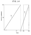
- Fig. 14 displays grayscales of 256 gradations.
- the first field is allocated to a case in which the brightness is equal to or less than a 171th gradation.
- an output from the second field may be set to zero. That is, when the gradation is equal to or less than the 171th gradation, it is possible to perform the black insertion without lowering the brightness.
- the gradation exceeds the 171th gradation, for example, when the gradation shown in Fig. 14 is a 200th gradation, the brightness data is also outputted from the second field and hence, a complete black insertion effect cannot be obtained.
- the brightness in the second field is smaller than the brightness in the first field and hence, some effect against the moving image blurring is acquired.
- Specific means are as follows.
- the above-mentioned means (2) by dividing 1 frame into 3 fields and by always performing a black display in one field, it is possible to surely perform black insertion even with the high brightness thus surely reducing moving image blurring even with the high brightness. Further, even when the black display is performed on the whole 1 field, a period for the black display is 1/3 of the frame period and hence, lowering of the brightness is limited.
- Fig. 1 is a block diagram showing the constitution of the liquid crystal display device.
- the display device corresponds to a display of 16, 770, 000 colors in total in which respective colors of R, G, B are constituted of 256 gradations.
- Numeral 101 indicates input display data formed of 24 bits in total in which respective colors of R, G, B are constituted of 8 bits, and
- numeral 102 indicates a group of input signals.
- the group of input signals 102 is constituted of a vertical synchronizing signal Vsync which defines 1 frame period (period in which 1 screen is displayed), a horizontal synchronizing signal Hsync which defines 1 horizontal period (period in which 1 line is displayed), a display timing signal DISP which defines an effective period of display data, and a reference clock signal DCLK which is synchronized with display data.
- Numeral 103 indicates a drive selection signal.
- a conventional drive method or a drive method which reduces moving image blurring is selected.
- the input display data 101, a group of input signal 102, and the drive selection signal 103 are transferred from an external system (for example, a television receiver set, a PV set or a mobile phone set).
- Numeral 104 indicates a timing signal generation circuit
- numeral 105 indicates a group of memory control signals
- numeral 106 indicates a table initializing signal
- numeral 107 indicates a data selection signal
- numeral 108 indicates a group of data driver control signals
- numeral 109 indicates a group of scanning driver control signals.
- the group of data driver control signals 108 is constituted of an output signal CL1 which defines output timing of a gradation voltage based on the display data, an AC signal M which determines polarity of a source voltage, and a clock signal PCLK which is synchronized with the display data.
- the group of scanning driver control signals 109 is constituted of a shift signal CL3 which defines a scanning period for 1 line, and a vertical start signal FLM which defines starting of scanning of a head line.
- Numeral 110 indicates a frame memory having capacitance amounting at least 1 frame of the display data and performs reading and writing processing of display data based on the group of memory signals 105.
- Numeral 111 indicates memory read data which is read from the frame memory 110 in response to the group of the memory control signals 105.
- Numeral 112 indicates a ROM (Read Only Memory) which outputs data stored in the inside thereof in response to the table initializing signal,
- numeral 113 indicates table data which is outputted from the ROM 112,
- numeral 114 indicates a first field conversion table,
- numeral 115 indicates a second field conversion table, and
- numeral 116 indicates a third field conversion table.
- Values of respective tables are set based on the table data 113 at the time of supplying electricity, and the memory read data 111 read from the frame memory 110 is converted based on the values set in the respective tables.
- the first field conversion table 114 has a function of a data conversion circuit for the first field
- the second field conversion table 115 has a function of a data conversion circuit for the second field
- the third field conversion table 116 has a function of a data conversion circuit for the third field.
- Numeral 117 indicates first field display data acquired by conversion in the first field conversion table 114
- numeral 118 indicates second field display data acquired by conversion in the second field conversion table 115
- numeral 119 indicates third field display data acquired by conversion in the third field conversion table 116.
- Numeral 120 indicates a display data selection circuit. The display data selection circuit 120 selects and outputs any one of the first field display data 117, the second field display data 118 and the third field display data 119 based on the data selection signal 107.
- Numeral 121 indicates field display data selected by the display data selection circuit 120.
- Numeral 122 indicates a gradation voltage generation circuit
- numeral 123 indicates a gradation voltage
- Numeral 124 indicates a data driver.
- the data driver 124 generates potentials of 512 levels in total consisting of 256 levels (2 8 powers of 2)) for positive polarity and negative polarity respectively from the gradation voltage 123 and, at the same time, selects a potential of 1 level corresponding to the field display data 121 of 8 bits for respective colors and a polarity signal M, and applies the potential to a liquid crystal display panel 128 as a data voltage.
- Numeral 125 indicates a data voltage generated by the data driver 124.
- Numeral 126 indicates a scanning driver, and numeral 127 indicates a scanning line selection signal.
- the scanning driver 126 generates a scanning line selection signal 127 in response to the group of scanning driver control signals 109, and outputs the scanning line selection signal 127 to scanning lines of the liquid crystal display panel 128.
- 1 pixel of the liquid crystal display panel 128 is schematically indicated by numeral 129.
- 1 pixel of the liquid crystal display panel 128 is constituted of a TFT (Thin Film Transistor) which is formed of a source electrode, a gate electrode and a drain electrode, a liquid crystal layer and a counter electrode.
- the TFT performs a switching operation when the scanning signal is applied to the gate electrode thereof.
- the data voltage is written in the source electrode which is connected with one side of the liquid crystal layer via the drain electrode when the TFT is in an open state, and the voltage written in the source electrode is held when the TFT is in a closed state. Assume the voltage of the source electrode as Vs and a counter electrode voltage as Vcom.
- the liquid crystal layer changes the polarization direction based on the potential difference between the source electrode voltage Vs and the counter electrode voltage Vcom and, at the same time, a transmission light quantity from a backlight arranged on a back surface of the liquid crystal display panel 128 is changed via the polarizer arranged above and below the liquid crystal layer thus performing a gradation display.
- the first field is a brightest field
- the second field is an intermediate brightness field
- the third field is the darkest field.
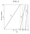
- Fig. 2 shows an example of a range of gradations which are allocated to the respective fields.
- the gradations are taken on an axis of abscissas and the relative brightness is taken on an axis of ordinates, wherein the maximum gradation is a 255th gradation which corresponds to 256 bits.
- the gradation is relatively low, that is, when the gradation takes a value equal to or below a 171th gradation, only the field which is allocated to 1g contributes to the formation of images.
- the field allocated to 1g and the field allocated to 2g contribute to the formation of images.
- the gradation takes a value which exceeds the 228th gradation, all of the fields allocated to 1g, 2g, 3g contribute to the formation of images.
- the gradation assumes the maximum gradation which is a 256th gradation, all fields ranging from the first field to the third field assume the maximum brightness and hence, a white peak is displayed.
- the relationship between the gradations and the brightness is set linearly in Fig. 2. However, this relationship can be changed depending on properties or the like of an actual liquid crystal display panel.
- the conversion tables corresponding to the respective fields are written in the ROM shown in Fig. 1 based on the relationship, and the first field conversion table, the second field conversion table and the third field conversion table read the conversion tables each time the display device is turned on.
- the respective conversion tables include the number of data equal to the number of frame data of the input data, the respective conversion tables differ from each other in the relationship between the gradations and the brightness.
- the field display data ranging from the first field to the third field is read by the display data selection circuit and is outputted to the data driver.
- a reading speed of the respective fields is three times as fast as the reading speed of the input data.
- the relationships between the gradations and brightness (hereinafter, also referred to as gradation-brightness characteristics) 1g, 2g, 3g shown in Fig. 2 are candidates for tables allocated to respective fields. For example, when necessary, the relationship 1g may be allocated to the third field, the relationship 3g may be allocated to the first field, and the relationship 2g may be allocated to the second field. As will be explained later, this manner of allocation brings about effects for preventing moving image blurring which differ from each other.
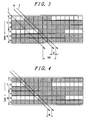
- Fig. 3 shows the case in which the gradation-brightness characteristic 1g shown in Fig. 2 is allocated to the first field.
- a lapse of time is taken on an axis of ordinates, wherein symbol 1F indicates 1 frame period, symbol 1f indicates a first field, symbol 2f indicates a second field, and symbol 3f indicates a third field. That is, Fig.
- FIG. 3 shows that 1 frame is constituted of 3 fields. The movement of an image within the corresponding time is taken on an axis of abscissas. In Fig. 3, 3 pixels are assumed to move within 1 frame period. Although a moving quantity of the pixel is set small for the sake of brevity, the same idea is fundamentally applicable even when the moving quantity of the pixel is increased.
- an arrow J shows the movement of an image which human eyes predict when the image is moved.
- the brightness of the pixel is fixed during 1 field and hence, an image indicated by an arrow K is also recognized by the human eyes and hence, the difference B between the arrow J and the arrow K is recognized as moving image blurring by the human eyes.
- a quantity of moving image blurring which the human eyes recognize when the black insertion is not performed is expressed as the difference BB between the arrow J and an arrow L shown in Fig. 3. It is understood from Fig. 3 that the quantity of moving image blurring is largely reduced compared to the quantity of moving image blurring of the conventional example.
- Fig. 4 shows a case in which the gradation-brightness characteristic 1g shown in Fig. 2 is made to correspond to the second field. Also in this case, a quantity of moving image blurring is substantially equal to the quantity of the moving image blurring in the case in which the gradation-brightness characteristic 1g is made to correspond to the first field shown in Fig. 2. Although not shown in the drawing, a quantity of moving image blurring is substantially equal to the quantity of the moving image blurring in the case in which the gradation-brightness characteristic 1g is made to correspond to the third field shown in Fig. 2.
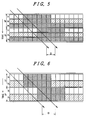
- Fig. 5 shows a case in which the gradation-brightness characteristic 1g shown in Fig. 2 is made to correspond to the first field, the gradation-brightness characteristic 2g shown in Fig. 2 is made to correspond to the second field, and the gradation-brightness 3g shown in Fig. 2 is made to correspond to the third field.
- This case is referred to as a first mode.
- a value of B in Fig. 5 indicates a quantity of moving image blurring.
- Fig. 6 shows a case in which 1 frame is expressed by 2 fields for a comparison purpose. This case also corresponds to the case of the 200th gradation in Fig. 2.
- Fig. 5 shows a case in which the gradation-brightness characteristic 1g shown in Fig. 2 is made to correspond to the first field
- the gradation-brightness characteristic 2g shown in Fig. 2 is made to correspond to the second field
- the gradation-brightness 3g shown in Fig. 2 is made to
- Symbol B in Fig. 6 indicates a quantity of moving image blurring. As can be understood from a comparison of Fig. 5 and Fig. 6, the moving image blurring can be reduced more effectively in the case shown in Fig. 5 than the case shown in Fig. 6.
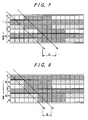
- Fig. 7 shows a case in which the gradation-brightness characteristic 1g shown in Fig. 2 is made to correspond to the first field, the gradation-brightness characteristic 2g shown in Fig. 2 is made to correspond to the third field, and the gradation-brightness 3g shown in Fig. 2 is made to correspond to the second field.
- This case is referred to as a second mode.
- moving image blurring is expressed as a value B shown in Fig. 7.
- a quantity of moving image blurring is increased.
- the quantity of moving image blurring becomes substantially equal to the quantity of moving image blurring in the case in which 1 frame is expressed by 2 fields.
- Fig. 8 shows a case in which the gradation-brightness characteristic 1g shown in Fig. 2 is made to correspond to the third field, the gradation-brightness characteristic 2g shown in Fig. 2 is made to correspond to the second field, and the gradation-brightness characteristic 3g shown in Fig. 2 is made to correspond to the first field.
- This case is referred to as a third mode.
- a quantity of moving image blurring in this case is expressed by symbol B shown in Fig. 8.
- the moving image blurring is reduced and a quantity of B is substantially equal to the quantity of B in the first mode.
- the blurring reduction effect becomes least when there is no black display immediately before the frame is changed or immediately after the frame is changed. That is, it is necessary to obviate these combinations. While it is possible to obtain a large moving image blurring reduction effect when the field of black display exists immediately before the frame is changed or immediately after the frame is changed, such an effect can be further increased by eliminating the brightest field immediately before the black field.
- Fig. 9 shows 6 cases for 2 frames.
- 1 frame is formed of 3 fields, wherein 1g, 2g, 3g respectively correspond to the gradation-brightness characteristics shown in Fig. 2.
- the case 1 shown in Fig. 9 corresponds to the above-mentioned first mode and exhibits the largest moving image blurring reduction effect.
- the case 9 corresponds to the above-mentioned third mode and exhibits the moving image blurring reduction effect substantially equal to the moving image blurring reduction ef fect of the above-mentioned first mode.
- the cases which exhibit the least moving image blurring reduction effect are the case 2 and the case 4 which correspond to the above-mentioned second mode. These cases should be obviated from a viewpoint of the moving image blurring reduction.
- the case 3 and the case 5 do not belong to any modes, these cases exhibit the moving image blurring reduction ef fect substantially equal to the moving image blurring reduction effect of the above-mentioned first mode or third mode only under the condition that 3g is black.
- the correspondence between the respective fields and the respective gradation-brightness characteristics may be written in the ROM 113 shown in Fig. 1.
- this embodiment reduces the moving image blurring by expressing 1 frame using 3 fields
- this embodiment describes that the moving image blurring reduction effect largely differs depending on setting of the gradation-brightness characteristics of respective fields. Further, by setting the field exhibiting the lowest brightness (gradation-brightness characteristic 3g shown in Fig. 2) immediately before or immediately after the frame is changed, and by obviating the setting of the field exhibiting the maximum brightness (gradation-brightness characteristic 1g shown in Fig. 2) immediately before the field exhibiting the lowest brightness, it is possible to obtain a large moving image blurring reduction effect.
- the embodiment 1 reduces the moving image blurring by expressing the image corresponding to 1 frame using 3 fields
- 1 frame is expressed by n pieces of fields for finely reducing the moving image blurring.
- Fig. 10 shows such an example in which 1 frame is expressed by 5 fields.
- a gradation 1T up to a gradation 1T, only the field corresponding to the gradation-brightness characteristic 1g expresses an image and other fields perform a black display.
- the field corresponding to the gradation-brightness characteristic 1g and the field corresponding to the gradation-brightness characteristic 2g express an image, and other fields perform a black display. In this manner, by dividing 1 frame into the larger number of fields, chances of inserting black in various screens are increased and hence, the image blurring can be reduced correspondingly.
- the system for this case is configured such that, in Fig. 1, the capacitance of the frame memory 110, the capacitance of ROM 113, and the number of conversion tables 114, 115, 116 and the like corresponding to the gradation-brightness characteristics are increased corresponding to the number of fields. Further, a speed for writing field display data into the data driver 124 becomes 5 times as fast as a corresponding speed of the input data 101.
- the combination which is considered first is a method which arranges the brightest gradation-brightness characteristic 1g in Fig. 10 at the center of the frame.
- the gradation-brightness characteristic 1g is allocated to the third field
- the gradation-brightness characteristic 2g is allocated to the fourth field
- the gradation-brightness characteristic 3g is allocated to the fifth field
- the gradation-brightness characteristic 4g is allocated to the first field
- the gradation-brightness characteristic 5g is allocated to the second field.
- the moving image blurring is expressed by symbol B in Fig. 11.
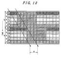
- Fig. 12 although the gradation-brightness characteristic 1g shown in Fig. 10 is allocated to the third field and the gradation-brightness characteristic 2g shown in Fig. 10 is allocated to the fourth field in the same manner as the case shown in Fig. 11, the gradation-brightness characteristic 5g is allocated to the fifth field and the gradation-brightness characteristic 4g is allocated to the first field.
- the case shown in Fig. 12 is characterized by setting the minimum gradation-brightness characteristic 5g (black in this case) at the final field of 1 frame.
- the similar advantageous effects can be also obtained by allocating the minimum gradation-brightness characteristic 5g to the initial field of 1 frame. Further, in Fig. 12, the next minimum gradation-brightness characteristic 4g is arranged in the initial field of the frame. By setting the gradation-brightness characteristics in this manner, it is possible to further increase a black insertion effect with respect to an image which uses the gradation-brightness characteristic 3g. Further, as can be understood from Fig. 12, by continuously arranging the fields which are allocated to the high gradation-brightnesscharacteristicslg,2g,itispossible to cope with the moving image blurring more effectively.
- the gradation-brightness characteristic 5g which has the highest probability of performing a black display is set in the initial or final field and hence, it is possible to acquire the substantially equal image blurring reduction effect.
- the embodiment 1 and the embodiment 2 cope with the moving image blurring by forming 1 frame using 3 or more fields which differ from each other in the gradation-brightness characteristic.
- the brightness approximates the maximum brightness
- an image display is performed in all fields and hence, the black display is not performed whereby the moving image blurring cannot be eliminated.
- no signal is written in 1 field and the field always performs a black display.
- a crucial point in this embodiment lies in that the field in which the black display is always performed is set to either an initial field or a last field of the frame.
- the combination of the fields and the gradation-brightness characteristics when the black display is always performed in 1 field does not essentially differ from the corresponding combination in the embodiment 1. That is, by using the field which always per forms the black display in place of the gradation-brightness characteristic 3g in the embodiment 1, it is possible to acquire a moving image blurring reduction effect.
- the combination of the fields and the gradation-brightness characteristics when the black display is always performed in 1 field does not substantially differ from the corresponding combination in the embodiment 2. That is, with the use of the field in which the black is always displayed in place of the lowest gradation-brightness characteristic in the embodiment 2, it is possible to acquire the moving image blurring reduction effect.
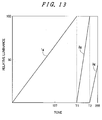
- Fig. 13 shows a fourth embodiment.
- the embodiment 1 and the embodiment 2 display the maximum brightness in all fields at the maximum gradation and hence, there is no reduction of the moving image blurring due to black insertion.
- Fig. 13 shows a case in which 1 frame is formed of 3 fields.
- a region exhibiting the gradation-brightness characteristic 3g is used.
- the gradation-brightness characteristic 3g is set smaller than the maximum brightness. Due to such setting, it is possible to acquire at least two following advantageous effects.
- the gradation T2 which moves from the gradation-brightness characteristic 2g to the gradation-brightness characteristic 3g can be increased.
- the gradation-brightness characteristic 3g to express the brightness change from the minimum brightness to the maximum brightness, it is necessary to ensure the gradations within a fixed range.
- the gradation range of the gradation-brightness characteristic 3g can be reduced whereby the value of T2 in Fig. 13 can be increased correspondingly. Accordingly, chances that the region of the gradation-brightness characteristic 3g is used can be reduced thus enhancing the moving image blurring reduction effect attributed to black insertion.
- Another advantageous effect is that the maximum brightness at the gradation-brightness characteristic 3g can be lowered and hence, even when the region of the gradation-brightness characteristic 3g is used, it is possible to reduce an image retention effect on naked eyes corresponding to the lowering of the brightness.
- Fig. 13 shows a case in which 1 frame is formed of 3 fields
- the same advantageous effects can be acquired by forming 1 frame using n pieces of fields.
- the maximum brightness of the field which is allocated to the region of the highest gradation is set lower than the brightnesses of other fields.
- the moving image blurring can be reduced due to the substantially same reasons as the above-mentioned case in which 1 frame is formed using 3 fields.
- the advantageous effects acquired when this embodiment is applied to n pieces of fields are limited by an amount that the number of fields is increased.
- the case which forms 1 frame using n pieces of fields can further reduce the lowering of brightness than the case which forms 1 frame using 3 fields.
- the number of fields may be selected or determined based on properties of an image to be displayed.
- the present invention is also applicable to an organic EL display device which adopts TFTs in the substantially same manner.
- the present invention reduces moving image blurring in a hold-response-type display device.
- 1 frame is divided into 3 fields. Assuming the gradation-brightness characteristic of a first field as 1g, the gradation-brightness characteristic of a second field as 2g, and the gradation-brightness characteristic of a third field as 3g, the third field is set at an initial stage or at a final stage of the frame. Due to such setting, the moving image blurring can be effectively reduced up to the relatively high brightness.
Landscapes
- Engineering & Computer Science (AREA)
- Physics & Mathematics (AREA)
- Computer Hardware Design (AREA)
- General Physics & Mathematics (AREA)
- Theoretical Computer Science (AREA)
- Chemical & Material Sciences (AREA)
- Crystallography & Structural Chemistry (AREA)
- Control Of Indicators Other Than Cathode Ray Tubes (AREA)
- Liquid Crystal Display Device Control (AREA)
- Liquid Crystal (AREA)
- Electroluminescent Light Sources (AREA)
- Control Of El Displays (AREA)
Applications Claiming Priority (1)
| Application Number | Priority Date | Filing Date | Title |
|---|---|---|---|
| JP2006252137A JP2008076433A (ja) | 2006-09-19 | 2006-09-19 | 表示装置 |
Publications (2)
| Publication Number | Publication Date |
|---|---|
| EP1903545A2 true EP1903545A2 (de) | 2008-03-26 |
| EP1903545A3 EP1903545A3 (de) | 2008-11-19 |
Family
ID=38846874
Family Applications (1)
| Application Number | Title | Priority Date | Filing Date |
|---|---|---|---|
| EP07017744A Withdrawn EP1903545A3 (de) | 2006-09-19 | 2007-09-11 | Anzeigevorrichtung |
Country Status (6)
| Country | Link |
|---|---|
| US (1) | US20080068395A1 (de) |
| EP (1) | EP1903545A3 (de) |
| JP (1) | JP2008076433A (de) |
| KR (1) | KR100935404B1 (de) |
| CN (1) | CN101150656A (de) |
| TW (1) | TW200832345A (de) |
Cited By (1)
| Publication number | Priority date | Publication date | Assignee | Title |
|---|---|---|---|---|
| US10991338B2 (en) | 2010-03-25 | 2021-04-27 | Nokia Technologies Oy | Apparatus, display module and method for adaptive blank frame insertion |
Families Citing this family (6)
| Publication number | Priority date | Publication date | Assignee | Title |
|---|---|---|---|---|
| KR101350398B1 (ko) | 2006-12-04 | 2014-01-14 | 삼성디스플레이 주식회사 | 표시 장치 및 구동 방법 |
| JP2008256954A (ja) * | 2007-04-05 | 2008-10-23 | Hitachi Displays Ltd | 表示装置 |
| WO2011040077A1 (ja) * | 2009-09-29 | 2011-04-07 | シャープ株式会社 | 映像出力装置及び映像の合成方法 |
| US9805662B2 (en) * | 2015-03-23 | 2017-10-31 | Intel Corporation | Content adaptive backlight power saving technology |
| CN112992065B (zh) * | 2021-04-22 | 2022-04-15 | 昆山国显光电有限公司 | 显示面板的亮度调节方法、亮度调节装置、计算机可读存储介质 |
| KR20230074375A (ko) * | 2021-11-19 | 2023-05-30 | 삼성디스플레이 주식회사 | 표시 장치 및 이의 구동 방법 |
Citations (6)
| Publication number | Priority date | Publication date | Assignee | Title |
|---|---|---|---|---|
| US6473117B1 (en) | 1999-08-24 | 2002-10-29 | Canon Kabushiki Kaisha | Driving method for liquid crystal device |
| US20030107538A1 (en) | 1998-06-24 | 2003-06-12 | Yasufumi Asao | Display apparatus, liquid crystal display apparatus and driving method for display apparatus |
| US20030179221A1 (en) * | 2002-03-20 | 2003-09-25 | Hiroyuki Nitta | Display device |
| US20040155847A1 (en) | 2003-02-07 | 2004-08-12 | Sanyo Electric Co., Ltd. | Display method, display apparatus and data write circuit utilized therefor |
| EP1536407A2 (de) * | 2003-11-17 | 2005-06-01 | Sharp Kabushiki Kaisha | Bildanzeigevorrichtung, elektronisches Gerät, Fernsehgerät mit Flüssigkristallen, Flüssigkristallsteuereinrichtung, Verfahren zur Bildanzeige, Programm zur Anzeigesteuerung und computerlesbares Aufzeichnungsmedium |
| EP1647966A1 (de) | 2004-10-18 | 2006-04-19 | Tohoku Pioneer Corporation | Treiberschaltung fur eine Licht emittierende Anzeigetafel und eine elektronische Maschine, auf der die Treiberschaltung montiert ist |
Family Cites Families (9)
| Publication number | Priority date | Publication date | Assignee | Title |
|---|---|---|---|---|
| JP4655341B2 (ja) * | 2000-07-10 | 2011-03-23 | 日本電気株式会社 | 表示装置 |
| KR100457484B1 (ko) * | 2001-01-22 | 2004-11-17 | 마쯔시다덴기산교 가부시키가이샤 | 표시 장치 및 그 구동 방법 |
| JP3750548B2 (ja) * | 2001-03-19 | 2006-03-01 | セイコーエプソン株式会社 | 液晶表示装置、液晶表示装置の駆動方法、液晶表示装置の駆動回路および電子機器 |
| JP2003114646A (ja) * | 2001-08-03 | 2003-04-18 | Semiconductor Energy Lab Co Ltd | 表示装置及びその駆動方法。 |
| JP3767737B2 (ja) * | 2001-10-25 | 2006-04-19 | シャープ株式会社 | 表示素子およびその階調駆動方法 |
| JP3653506B2 (ja) * | 2002-03-20 | 2005-05-25 | 株式会社日立製作所 | 表示装置及びその駆動方法 |
| EP1422928A3 (de) * | 2002-11-22 | 2009-03-11 | Panasonic Corporation | Bewegungskompensierte Interpolation digitaler Videosignale |
| FR2857147A1 (fr) * | 2003-07-01 | 2005-01-07 | Thomson Licensing Sa | Procede de traitement d'une sequence d'images video dans un panneau d'affichage a cristaux liquides |
| JP2006221060A (ja) * | 2005-02-14 | 2006-08-24 | Sony Corp | 映像信号処理装置、映像信号の処理方法、映像信号の処理プログラム及び映像信号の処理プログラムを記録した記録媒体 |
-
2006
- 2006-09-19 JP JP2006252137A patent/JP2008076433A/ja active Pending
-
2007
- 2007-09-11 EP EP07017744A patent/EP1903545A3/de not_active Withdrawn
- 2007-09-11 US US11/898,280 patent/US20080068395A1/en not_active Abandoned
- 2007-09-12 TW TW096134086A patent/TW200832345A/zh unknown
- 2007-09-18 KR KR1020070094644A patent/KR100935404B1/ko not_active Expired - Fee Related
- 2007-09-18 CN CNA2007101533569A patent/CN101150656A/zh active Pending
Patent Citations (6)
| Publication number | Priority date | Publication date | Assignee | Title |
|---|---|---|---|---|
| US20030107538A1 (en) | 1998-06-24 | 2003-06-12 | Yasufumi Asao | Display apparatus, liquid crystal display apparatus and driving method for display apparatus |
| US6473117B1 (en) | 1999-08-24 | 2002-10-29 | Canon Kabushiki Kaisha | Driving method for liquid crystal device |
| US20030179221A1 (en) * | 2002-03-20 | 2003-09-25 | Hiroyuki Nitta | Display device |
| US20040155847A1 (en) | 2003-02-07 | 2004-08-12 | Sanyo Electric Co., Ltd. | Display method, display apparatus and data write circuit utilized therefor |
| EP1536407A2 (de) * | 2003-11-17 | 2005-06-01 | Sharp Kabushiki Kaisha | Bildanzeigevorrichtung, elektronisches Gerät, Fernsehgerät mit Flüssigkristallen, Flüssigkristallsteuereinrichtung, Verfahren zur Bildanzeige, Programm zur Anzeigesteuerung und computerlesbares Aufzeichnungsmedium |
| EP1647966A1 (de) | 2004-10-18 | 2006-04-19 | Tohoku Pioneer Corporation | Treiberschaltung fur eine Licht emittierende Anzeigetafel und eine elektronische Maschine, auf der die Treiberschaltung montiert ist |
Cited By (1)
| Publication number | Priority date | Publication date | Assignee | Title |
|---|---|---|---|---|
| US10991338B2 (en) | 2010-03-25 | 2021-04-27 | Nokia Technologies Oy | Apparatus, display module and method for adaptive blank frame insertion |
Also Published As
| Publication number | Publication date |
|---|---|
| CN101150656A (zh) | 2008-03-26 |
| EP1903545A3 (de) | 2008-11-19 |
| TW200832345A (en) | 2008-08-01 |
| KR20080026054A (ko) | 2008-03-24 |
| KR100935404B1 (ko) | 2010-01-06 |
| US20080068395A1 (en) | 2008-03-20 |
| JP2008076433A (ja) | 2008-04-03 |
Similar Documents
| Publication | Publication Date | Title |
|---|---|---|
| US7847782B2 (en) | Method and apparatus for driving liquid crystal display | |
| CN100465709C (zh) | 驱动液晶显示器件的装置和方法 | |
| US20080246784A1 (en) | Display device | |
| JP2006343706A (ja) | 表示装置 | |
| CN101281716B (zh) | 显示装置 | |
| KR20100055880A (ko) | 표시 장치 및 이의 구동 방법 | |
| EP1903545A2 (de) | Anzeigevorrichtung | |
| US7817169B2 (en) | Display device | |
| US8633880B2 (en) | Display device with improved smooth tone display utilizing different sets of tone voltages converted from display data based on different conversion charateristics | |
| KR101415062B1 (ko) | 액정표시장치 및 그 구동방법 | |
| US8134530B2 (en) | Liquid crystal display device and method of driving the same | |
| KR101408254B1 (ko) | 액정표시장치의 응답시간 개선 장치 및 방법 | |
| CN101149896B (zh) | 显示装置 | |
| KR101633114B1 (ko) | 액정표시장치 및 그의 화질 제어방법 | |
| KR101594617B1 (ko) | 액정표시장치 | |
| KR20070041845A (ko) | 액정표시장치와, 이의 구동 장치 및 방법 | |
| US8044904B2 (en) | Display device | |
| KR20100076605A (ko) | 액정표시장치 및 그 구동방법 | |
| US20090096733A1 (en) | Liquid crystal display device | |
| JP2008102220A (ja) | 映像表示装置 |
Legal Events
| Date | Code | Title | Description |
|---|---|---|---|
| PUAI | Public reference made under article 153(3) epc to a published international application that has entered the european phase |
Free format text: ORIGINAL CODE: 0009012 |
|
| AK | Designated contracting states |
Kind code of ref document: A2 Designated state(s): AT BE BG CH CY CZ DE DK EE ES FI FR GB GR HU IE IS IT LI LT LU LV MC MT NL PL PT RO SE SI SK TR |
|
| AX | Request for extension of the european patent |
Extension state: AL BA HR MK YU |
|
| PUAL | Search report despatched |
Free format text: ORIGINAL CODE: 0009013 |
|
| AK | Designated contracting states |
Kind code of ref document: A3 Designated state(s): AT BE BG CH CY CZ DE DK EE ES FI FR GB GR HU IE IS IT LI LT LU LV MC MT NL PL PT RO SE SI SK TR |
|
| AX | Request for extension of the european patent |
Extension state: AL BA HR MK RS |
|
| 17P | Request for examination filed |
Effective date: 20081201 |
|
| 17Q | First examination report despatched |
Effective date: 20090115 |
|
| AKX | Designation fees paid |
Designated state(s): AT BE BG CH CY CZ DE DK EE ES FI FR GB GR HU IE IS IT LI LT LU LV MC MT NL PL PT RO SE SI SK TR |
|
| RAP1 | Party data changed (applicant data changed or rights of an application transferred) |
Owner name: PANASONIC LIQUID CRYSTAL DISPLAY CO., LTD. Owner name: HITACHI DISPLAYS, LTD. |
|
| STAA | Information on the status of an ep patent application or granted ep patent |
Free format text: STATUS: THE APPLICATION IS DEEMED TO BE WITHDRAWN |
|
| 18D | Application deemed to be withdrawn |
Effective date: 20121030 |