US7847782B2 - Method and apparatus for driving liquid crystal display - Google Patents
Method and apparatus for driving liquid crystal display Download PDFInfo
- Publication number
- US7847782B2 US7847782B2 US10/880,220 US88022004A US7847782B2 US 7847782 B2 US7847782 B2 US 7847782B2 US 88022004 A US88022004 A US 88022004A US 7847782 B2 US7847782 B2 US 7847782B2
- Authority
- US
- United States
- Prior art keywords
- brightness
- data
- histogram
- components
- histograms
- Prior art date
- Legal status (The legal status is an assumption and is not a legal conclusion. Google has not performed a legal analysis and makes no representation as to the accuracy of the status listed.)
- Active, expires
Links
Images


Classifications
-
- G—PHYSICS
- G09—EDUCATION; CRYPTOGRAPHY; DISPLAY; ADVERTISING; SEALS
- G09G—ARRANGEMENTS OR CIRCUITS FOR CONTROL OF INDICATING DEVICES USING STATIC MEANS TO PRESENT VARIABLE INFORMATION
- G09G3/00—Control arrangements or circuits, of interest only in connection with visual indicators other than cathode-ray tubes
- G09G3/20—Control arrangements or circuits, of interest only in connection with visual indicators other than cathode-ray tubes for presentation of an assembly of a number of characters, e.g. a page, by composing the assembly by combination of individual elements arranged in a matrix no fixed position being assigned to or needed to be assigned to the individual characters or partial characters
- G09G3/34—Control arrangements or circuits, of interest only in connection with visual indicators other than cathode-ray tubes for presentation of an assembly of a number of characters, e.g. a page, by composing the assembly by combination of individual elements arranged in a matrix no fixed position being assigned to or needed to be assigned to the individual characters or partial characters by control of light from an independent source
- G09G3/3406—Control of illumination source
-
- G—PHYSICS
- G02—OPTICS
- G02F—OPTICAL DEVICES OR ARRANGEMENTS FOR THE CONTROL OF LIGHT BY MODIFICATION OF THE OPTICAL PROPERTIES OF THE MEDIA OF THE ELEMENTS INVOLVED THEREIN; NON-LINEAR OPTICS; FREQUENCY-CHANGING OF LIGHT; OPTICAL LOGIC ELEMENTS; OPTICAL ANALOGUE/DIGITAL CONVERTERS
- G02F1/00—Devices or arrangements for the control of the intensity, colour, phase, polarisation or direction of light arriving from an independent light source, e.g. switching, gating or modulating; Non-linear optics
- G02F1/01—Devices or arrangements for the control of the intensity, colour, phase, polarisation or direction of light arriving from an independent light source, e.g. switching, gating or modulating; Non-linear optics for the control of the intensity, phase, polarisation or colour
- G02F1/13—Devices or arrangements for the control of the intensity, colour, phase, polarisation or direction of light arriving from an independent light source, e.g. switching, gating or modulating; Non-linear optics for the control of the intensity, phase, polarisation or colour based on liquid crystals, e.g. single liquid crystal display cells
- G02F1/133—Constructional arrangements; Operation of liquid crystal cells; Circuit arrangements
-
- G—PHYSICS
- G09—EDUCATION; CRYPTOGRAPHY; DISPLAY; ADVERTISING; SEALS
- G09G—ARRANGEMENTS OR CIRCUITS FOR CONTROL OF INDICATING DEVICES USING STATIC MEANS TO PRESENT VARIABLE INFORMATION
- G09G2320/00—Control of display operating conditions
- G09G2320/02—Improving the quality of display appearance
- G09G2320/0271—Adjustment of the gradation levels within the range of the gradation scale, e.g. by redistribution or clipping
-
- G—PHYSICS
- G09—EDUCATION; CRYPTOGRAPHY; DISPLAY; ADVERTISING; SEALS
- G09G—ARRANGEMENTS OR CIRCUITS FOR CONTROL OF INDICATING DEVICES USING STATIC MEANS TO PRESENT VARIABLE INFORMATION
- G09G2320/00—Control of display operating conditions
- G09G2320/06—Adjustment of display parameters
- G09G2320/0626—Adjustment of display parameters for control of overall brightness
- G09G2320/0646—Modulation of illumination source brightness and image signal correlated to each other
-
- G—PHYSICS
- G09—EDUCATION; CRYPTOGRAPHY; DISPLAY; ADVERTISING; SEALS
- G09G—ARRANGEMENTS OR CIRCUITS FOR CONTROL OF INDICATING DEVICES USING STATIC MEANS TO PRESENT VARIABLE INFORMATION
- G09G2360/00—Aspects of the architecture of display systems
- G09G2360/16—Calculation or use of calculated indices related to luminance levels in display data
-
- G—PHYSICS
- G09—EDUCATION; CRYPTOGRAPHY; DISPLAY; ADVERTISING; SEALS
- G09G—ARRANGEMENTS OR CIRCUITS FOR CONTROL OF INDICATING DEVICES USING STATIC MEANS TO PRESENT VARIABLE INFORMATION
- G09G3/00—Control arrangements or circuits, of interest only in connection with visual indicators other than cathode-ray tubes
- G09G3/20—Control arrangements or circuits, of interest only in connection with visual indicators other than cathode-ray tubes for presentation of an assembly of a number of characters, e.g. a page, by composing the assembly by combination of individual elements arranged in a matrix no fixed position being assigned to or needed to be assigned to the individual characters or partial characters
- G09G3/2007—Display of intermediate tones
- G09G3/2077—Display of intermediate tones by a combination of two or more gradation control methods
Definitions
- This invention relates to a liquid crystal display, and more particularly to a driving method and apparatus for a liquid crystal display in which the contrast ratio of data to be displayed can be expanded and the brightness of a back light can be changed with the aid of an accumulated result of a plurality of frames.
- a liquid crystal display controls light transmittance of liquid crystal cells in accordance with video signals to thereby display a picture.
- Such an LCD has been implemented by an active matrix type having a switching device for each cell, and applied to a display device such as a monitor for a computer, office equipments, a cellular phone and the like.
- the switching device for the active matrix LCD mainly employs a thin film transistor (TFT).
- FIG. 1 schematically shows a conventional LCD driving apparatus.
- the conventional LCD driving apparatus includes a liquid crystal display panel 2 having m ⁇ n liquid crystal cells Clc arranged in a matrix type, m data lines D 1 to Dm and n gate lines G 1 to Gn intersecting each other and thin film transistors TFT provided at the intersections, a data driver 4 for applying data signals to the data lines D 1 to Dm of the liquid crystal display panel 2 , a gate driver 6 for applying scanning signals to the gate lines G 1 to Gn, a gamma voltage supplier 8 for supplying the data driver 4 with gamma voltages, a timing controller 10 for controlling the data driver 4 and the gate driver 6 using synchronizing signals from a system 20 , a direct current to direct current converter 14 , hereinafter referred to as “DC/DC converter”, for generating voltages supplied to the liquid crystal display panel 2 using a voltage from a power supply 12 , and an inverter 16 for driving a back light 18 .
- DC/DC converter direct current to direct current converter
- the system 20 applies vertical/horizontal signals Vsync and Hsync, clock signals DCLK, a data enable signal DE and data R, G and B to the timing controller 10 .
- the liquid crystal display panel 2 includes a plurality of liquid crystal cells Clc arranged, in a matrix type, at the intersections between the data lines D 1 to Dm and the gate lines G 1 to Gn.
- the thin film transistor TFT provided at each liquid crystal cell Clc applies a data signal from each data line D 1 to Dm to the liquid crystal cell Clc in response to a scanning signal from the gate line G.
- each liquid crystal cell Clc is provided with a storage capacitor Cst.
- the storage capacitor Cst is provided between a pixel electrode of the liquid crystal cell Clc and a pre-stage gate line or between the pixel electrode of the liquid crystal cell Clc and a common electrode line, to thereby constantly keep a voltage of the liquid crystal cell Clc.
- the gamma voltage supplier 8 applies a plurality of gamma voltages to the data driver 4 .
- the data driver 4 converts digital video data R, G and B into analog gamma voltages (i.e., data signals) corresponding to gray level values in response to a control signal CS from the timing controller 10 , and applies the analog gamma voltages to the data lines D 1 to Dm.
- analog gamma voltages i.e., data signals
- the gate driver 6 sequentially applies a scanning pulse to the gate lines G 1 to Gn in response to a control signal CS from the timing controller 10 to thereby select horizontal lines of the liquid crystal display panel 2 supplied with the data signals.
- the timing controller 10 generates the control signals CS for controlling the gate driver 6 and the data driver 4 using the vertical/horizontal synchronizing signals Vsync and Hsync and the clock signal DCLK inputted from the system 20 .
- the control signal CS for controlling the gate driver 6 is comprised of a gate start pulse GSP, a gate shift clock GSC and a gate output enable signal GOE, etc.
- the control signal CS for controlling the data driver 4 is comprised of a source start pulse SSP, a source shift clock SSC, a source output enable signal SOE and a polarity signal POL, etc.
- the timing controller 10 re-aligns the data R, G and B from the system 20 to apply them to the data driver 4 .
- the DC/DC converter 14 boosts or drops a voltage of 3.3V inputted from the power supply 12 to generate a voltage supplied to the liquid crystal display panel 2 .
- Such a DC/DC converter 14 generates a gamma reference voltage, a gate high voltage VGH, a gate low voltage VGL and a common voltage Vcom, etc.
- the inverter 16 applies a driving voltage (or driving current) for driving the back light 18 to the back light 18 .
- the back light 18 generates light corresponding to the driving voltage (or driving current) from the inverter 16 to apply it to the liquid crystal display panel 2 .
- a driving method and apparatus for a liquid crystal display are presented in which the contrast ratio of the data can be expanded and the brightness of a back light can be changed with the aid of an accumulated result of a plurality of frames.
- a method of driving a liquid crystal display includes converting first data of each frame into brightness components to arrange the data into a histogram; and generating second data having an expanded contrast using histograms of at least two frames.
- generating the second data includes storing the histograms; converting the stored histograms into an average value to generate an average histogram; and generating the second data using the average histogram.
- Generating the average histogram includes assigning a weighting value to the stored histogram.
- the weighting value assigned has increasing value with decreasing distance from the current frame.
- the method further includes controlling brightness of a back light using the histograms.
- Controlling the brightness of the back light includes extracting a control value from the average histogram; and controlling the brightness of the back light in correspondence with the control value.
- Controlling the brightness of the back light includes extracting each control value from the histogram for the plurality of frames; averaging the extracted control values to calculate a control value; and controlling the brightness of the back light in correspondence with the calculated control value.
- the control value is a most-frequent value or an average value of the brightness components of the histogram.
- a method of driving a liquid crystal display includes converting first data of each frame into brightness components and chrominance components; arranging the brightness components into a histogram; storing histograms for a plurality of frames; converting the stored histograms into an average value to generate an average histogram; converting brightness components of the average histogram to have an expanded contrast; generating second data having an expanded contrast using the converted brightness components and the chrominance components; and re-arranging the second data such that the second data can be applied to a liquid crystal display panel, thereby applying the re-arranged second data to a data driver.
- the method further includes delaying the chrominance components such that the chrominance components are synchronized with the converted brightness components.
- the method further includes converting synchronizing signals inputted in synchronization with the first data from the exterior to be synchronized with the second data.
- Storing the histograms for the plurality of frames includes storing histograms for at least two frames adjacent to the current frame.
- Generating the average histogram includes assigning a weighting value such that histograms closer to the current frame have increasing effect on the average histogram.
- the method further includes controlling brightness of a back light using the histograms of the plurality of frames.
- Controlling the brightness of the back light includes extracting a control value from the average histogram; and controlling the brightness of the back light in correspondence with the control value.
- Controlling the brightness of the back light includes extracting each control value from the histogram for the plurality of frames; averaging the extracted control values to calculate a control value; and controlling the brightness of the back light in correspondence with the calculated control value.
- a method of driving a liquid crystal display includes converting data of each frame into brightness components to arrange the data into a histogram; and controlling brightness of a back light using histograms of at least two frames.
- controlling the brightness includes converting the histograms for the at least two frames into an average value to generate an average histogram; extracting a control value from the average histogram; and controlling the brightness of the back light in correspondence with the control value.
- controlling the brightness includes extracting each control value from the histogram for the at least two frames; averaging the extracted control values to calculate a control value; and controlling the brightness of the back light in correspondence with the calculated control value.
- the control value is a most-frequent value or an average value of the brightness components of the histogram.
- the brightness components are divided into a plurality of brightness areas, and the brightness of the back light is controlled to correspond to a brightness area to which the control value belongs of the divided brightness areas.
- the brightness of the back light is set differently for each area to which the control value belongs.
- the method further includes assigning a weighting value to each of the histograms for the at least two frames such that the histogram has increasing effect with decreasing distance from the current frame with respect to the brightness of the back light.
- a driving apparatus for a liquid crystal display includes a brightness/color separator for extracting brightness components from first data of each frame; a histogram analyzer for converting the brightness components into a histogram; a storage for storing histograms for at least two frames analyzed by the histogram analyzer; an average value calculator for converting the histograms for the at least two frames stored in the storage into an average value to generate an average histogram; and a data processor for converting the brightness components to have an expanded contrast using the average histogram.
- the driving apparatus further includes a brightness/color mixer for generating a second data having an expanded contrast using converted brightness components and chrominance components from the data processor; and delay means for delaying the chrominance components such that the chrominance components are synchronized with the converted brightness components.
- the driving apparatus further includes a weighting value assigner for assigning a weighting value in which histograms for frames closer to the current frame have an increasing effect with decreasing distance from the current frame when the average histogram is produced.
- the average value calculator converts the control value from each histogram for the at least two frames to calculate an average control value.
- the driving apparatus further includes a back light controller for controlling the brightness of the back light using the control value of the average histogram or the average control value.
- FIG. 1 is a schematic block diagram showing a configuration of a conventional driving apparatus for a liquid crystal display
- FIG. 2 is a schematic block diagram showing a configuration of a driving apparatus for a liquid crystal display according to an embodiment of the present invention
- FIG. 3 is a block diagram of a first embodiment of the picture quality enhancer shown in FIG. 2 ;
- FIG. 4 is a graph showing an example of a histogram analyzed by the histogram analyzer shown in FIG. 3 ;
- FIG. 5 depicts a brightness area for controlling brightness at the back light controller shown in FIG. 3 ;
- FIG. 6 is a block diagram of a second embodiment of the picture quality enhancer shown in FIG. 2 ;
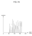
- FIG. 7A to FIG. 7D are graphs showing examples of a histogram stored in the storage unit shown in FIG. 6 ;
- FIG. 8 is a block diagram of a third embodiment of the picture quality enhancer shown in FIG. 2 .
- FIG. 2 schematically shows a driving apparatus for a liquid crystal display (LCD) according to an embodiment of the present invention.
- LCD liquid crystal display
- the LCD driving apparatus includes a liquid crystal display panel 22 having m ⁇ n liquid crystal cells Clc arranged in a matrix type, m data lines D 1 to Dm and n gate lines G 1 to Gn intersecting each other and thin film transistors TFT provided at the intersections, a data driver 24 for applying data signals to the data lines D 1 to Dm of the liquid crystal display panel 22 , a gate driver 26 for applying scanning signals to the gate lines G 1 to Gn, a gamma voltage supplier 28 for supplying the data driver 24 with gamma voltages, a timing controller 30 for controlling the data driver 24 and the gate driver 26 using a second synchronizing signal from a picture quality enhancer 42 , a DC/DC converter 34 for generating voltages supplied to the liquid crystal display panel 22 using a voltage from a power supply 32 , an inverter 36 for driving a back light unit 38 , and a picture quality enhancer 42 for selectively emphasizing a contrast of an input data and
- the system 40 applies first vertical/horizontal signals Vsync 1 and Hsync 1 , a first clock signal DCLK 1 , a first data enable signal DE 1 and first data Ri, Gi and Bi to the picture quality enhancer 42 .
- the liquid crystal display panel 22 includes a plurality of liquid crystal cells Clc arranged, in a matrix type, at the intersections between the data lines D 1 to Dm and the gate lines G 1 to Gn.
- the thin film transistor TFT provided at each liquid crystal cell Clc applies a data signal from each data line D 1 to Dm to the liquid crystal cell Clc in response to a scanning signal from the gate line G.
- each liquid crystal cell Clc is provided with a storage capacitor Cst.
- the storage capacitor Cst is provided between a pixel electrode of the liquid crystal cell Clc and a pre-stage gate line or between the pixel electrode of the liquid crystal cell Clc and a common electrode line, to thereby constantly keep a voltage of the liquid crystal cell Clc.
- the gamma voltage supplier 28 applies a plurality of gamma voltages to the data driver 24 .
- the data driver 24 converts digital video data Ro, Go and Bo into analog gamma voltages (i.e., data signals) corresponding to gray level values in response to a control signal CS from the timing controller 30 , and applies the analog gamma voltages to the data lines D 1 to Dm.
- the gate driver 26 sequentially applies a scanning pulse to the gate lines G 1 to Gn in response to a control signal CS from the timing controller 30 to thereby select horizontal lines of the liquid crystal display panel 22 supplied with the data signals.
- the timing controller 30 generates the control signals CS for controlling the gate driver 26 and the data driver 24 using second vertical/horizontal synchronizing signals Vsync 2 and Hsync 2 and a second clock signal DCLK 2 inputted from the picture quality enhancer 42 .
- the control signal CS for controlling the gate driver 26 is comprised of a gate start pulse GSP, a gate shift clock GSC and a gate output enable signal GOE, etc.
- the control signal CS for controlling the data driver 24 is comprised of a source start pulse SSP, a source shift clock SSC, a source output enable signal SOE and a polarity signal POL, etc.
- the timing controller 30 re-aligns second data Ro, Go and Bo from the picture quality enhancer 42 to apply the second data to the data driver 24 .
- the DC/DC converter 34 boosts or drops a voltage of 3.3V inputted from the power supply 32 to generate a voltage supplied to the liquid crystal display panel 22 .
- Such a DC/DC converter 14 generates a gamma reference voltage, a gate high voltage VGH, a gate low voltage VGL and a common voltage Vcom.
- the inverter 36 applies a driving voltage (or driving current) corresponding to the brightness control signal Dimming from the picture quality enhancer 42 to the back light 38 .
- a driving voltage (or driving current) applied from the inverter 36 to the back light 38 is determined by the brightness control signal Dimming from the picture quality enhancer 42 .
- the back light 38 applies a light corresponding to the driving voltage (or driving current) from the inverter 36 to the liquid crystal display panel 22 .
- the picture quality enhancer 42 extracts brightness components using the first data Ri, Gi and Bi from the system 40 , and generates second data Ro, Go and Bo obtained by a change in gray level values of the first data Ri, Gi and Bi in correspondence with the extracted brightness components. In this case, the picture quality enhancer 42 generates the second data Ro, Go and Bo such that the contrast is selectively expanded with respect to the input data Ri, Gi and Bi.
- the picture quality enhancer 42 generates a brightness control signal Dimming corresponding to brightness components to apply it to the inverter 36 .
- the picture quality enhancer 42 extracts a control value capable of controlling the back light, for example, a most-frequent value (i.e., the gray level value occupied by the maximum number of the brightness components in the frame) and/or an average value (i.e., the average value average value of the brightness components in the frame), and generates the brightness control signal Dimming using the extracted control value.
- the picture quality enhancer 42 divides the brightness of the back light corresponding to gray levels of the brightness components into at least two regions, and generates the brightness control signal Dimming such that a region of the brightness is selected in correspondence with the control value.
- the picture quality enhancer 42 generates second vertical/horizontal synchronizing signals Vsync 2 and Hsync 2 , a second clock signal DCLK 2 and a second data enable signal DE 2 synchronized with the second data Ro, Go and Bo with the aid of the first vertical/horizontal synchronizing signals Vsync 1 and Hsync 1 , the first clock signal DCLK 1 and the first data enable signal DE 1 inputted from the system 40 .
- the picture quality enhancer 42 includes an image signal modulator 70 for generating the second data Ro, Go and Bo using the first data Ri, Gi and Bi, a back light controller 72 for generating the brightness control signal Dimming under control of the image signal modulator 70 , and a control unit 68 for generating the second vertical/horizontal synchronizing signals Vsync 2 and Hsync 2 , the second clock signal DCLK 2 and the second enable signal DE 2 .
- the image signal modulator 70 extracts brightness components Y from the first data Ri, Gi and Bi, and generates second data Ro, Go and Bo in which the contrast is partially emphasized with the aid of the extracted brightness components Y.
- the image signal modulator 70 includes a brightness/color separator 50 , a, delay 52 , a brightness/color mixer 54 , a histogram analyzer 56 and a data processor 58 .
- the brightness/color separator 50 separates the first data Ri, Gi and Bi into brightness components Y and chrominance components U and V.
- the histogram analyzer 56 divides the brightness components Y into gray levels for each frame. In other words, the histogram analyzer 56 arranges the brightness components Y for each frame to correspond to the gray levels, thereby obtaining a histogram as shown in FIG. 4 .
- the shape of the histogram depends on the brightness components of the first data Ri, Gi and Bi.
- the data processor 58 generates modulated brightness components YM having a selectively emphasized contrast using the analyzed histogram from the histogram analyzer 56 .
- the data processor 58 generates modulated brightness components YM by various methods, such as those disclosed in Korean Patent Applications Nos. 2003-036289, 2003-040127, 2003-041127, etc., which have been filed previously by the applicants and are herein incorporated by reference in their entirety.
- the delay 52 delays chrominance components U and V until the brightness components YM modulated by the data processor 58 are produced. Further, the delay 52 applies the delayed chrominance components UD and VD to the bright/color mixer 54 to be synchronized with the modulated brightness components YM.
- the brightness/color mixer 54 generates second data Ro, Go and Bo with the aid of the modulated brightness components YM and the delayed chrominance components UD and VD.
- the second data Ro, Go and Bo obtained by the brightness/color mixer 54 has been produced from the modulated brightness components YM having an expanded contrast, they have more expanded contrast than the first data Ri, Gi and Bi.
- the second data Ro, Go and Bo produced such that the contrast can be expanded as mentioned above is applied to the timing controller 30 .
- the control unit 68 receives the first vertical/horizontal synchronizing signals Vsync 1 and Hsync 1 , the first clock signal DCLK 1 and the first data enable signal, DE 1 from the system 40 . Further, the controller 68 generates the second vertical/horizontal synchronizing signals Vsync 2 and Hsync 2 , the second clock signal DCLK 2 and the second data enable signal DE 2 to be synchronized with the second data Ro, Go and Bo, and applies them to the timing controller 30 .
- the back light controller 72 extracts a control value from the histogram analyzer 56 , and generates a brightness control signal Dimming using the extracted control value.
- the control value is variable, being dependent on the brightness components of each frame, and controls the brightness of the back light 38 .
- the control value can be, for example, the most-frequent and/or the average value.
- the back light controller 72 includes a control value extractor 60 and a back light control 64 .
- the back light control 64 divides the gray levels of the brightness components Y into a plurality of areas, and controls the back light 38 such that a different brightness can be supplied for each area. In other words, the back light control 64 determines the gray level of the control value, and generates a brightness control signal Dimming to correspond to the area to which the control value belongs.
- the control value extractor 60 extracts a control value from the histogram analyzer 56 to apply it to the back light control 64 .
- the control value extractor 60 extracts a histogram analyzed by the histogram analyzer 56 to apply it to the back light control 64 .
- the back light control 64 having received the control value checks the area to which a control value applied thereto belongs. In other words, the back light control 64 checks the area to which the control value belongs of a plurality of divided gray level values as shown in FIG. 5 , and generates a brightness control signal Dimming corresponding thereto.
- the brightness control signal Dimming from the back light control 64 is applied to the inverter 36 .
- the inverter 36 controls the back light 38 in response to the brightness control signal Dimming, thereby applying a light corresponding to the brightness control signal Dimming to the liquid crystal display panel 22 .
- the present embodiment generates the second data Ro, Go and Bo having a contrast expanded in correspondence with the brightness components Y for one frame of the first data Ri, Gi and Bi, thereby displaying a vivid image. Furthermore, the present embodiment controls brightness of the back light 38 in correspondence with the brightness components Y for one frame of the first data Ri, Gi and Bi, thereby displaying a vivid image.
- the brightness of the liquid crystal display panel 22 is controlled using only brightness components of one frame, then the brightness may be changed suddenly in each frame. If brightness is changed suddenly in each frame as mentioned above, then sparkling may occur at the liquid crystal display panel 22 .
- FIG. 6 a picture quality enhancer 42 according to another embodiment of the present invention is shown in FIG. 6 .
- the picture quality enhancer 42 includes an image signal modulator 100 for generating second data Ro, Go and Bo using first data Ri, Gi and Bi, a back light controller 102 for generating a brightness control signal Dimming under control of the image signal modulator 100 , and a control unit 122 for generating second vertical/horizontal synchronizing signals Vsync 2 and Hsync 2 , a second clock signal DCLK 2 and a second enable signal DE 2 .
- the control unit 122 receives first vertical/horizontal synchronizing signals Vsync 1 and Hsync 1 , a first clock signal DCLK 1 and a first data enable signal DE 1 from the system 40 . Further, the control unit 122 generates the second vertical/horizontal synchronizing signals Vsync 2 and Hsync 2 , the second clock signal DCLK 2 and the second data enable signal DE 2 to be synchronized with the second data Ro, Go and Bo, and applies them to the timing controller 30 .
- the image signal modulator 100 extracts brightness components Y from the first data Ri, Gi and Bi, and generates second data Ro, Go and Bo in which the contrast is partially emphasized with the aid of the extracted brightness components Y.
- the image signal modulator 100 includes a brightness/color separator 104 , a delay 106 , a brightness/color mixer 108 , a histogram analyzer 110 , a storage unit 112 , an average calculator 114 and a data processor 116 .
- the brightness/color separator 104 separates the first data Ri, Gi and Bi into brightness components Y and chrominance components U and V using the above equations (1) to (3).
- the histogram analyzer 110 divides the brightness components Y into gray levels for each frame. In other words, the histogram analyzer 110 arranges the brightness components Y of each frame to correspond to the gray levels, thereby obtaining a histogram as shown in FIG. 4 . As above, the shape of the histogram depends on the brightness components of the first data Ri, Gi and Bi.
- the storage unit 112 stores the histograms of at least two frames; the current frame and at least one earlier frame.
- the histograms of a plurality of frames adjacent to the current frame may be stored in the storage unit 112 .
- the histograms of the ten frames preceding the current frame, as well as that of the current frame may be stored in the storage unit 112 .
- the average value calculator 114 calculates the average value of the brightness components in the histogram in the storage unit 112 . For instance, each histogram having been stored in the storage unit 110 in shapes as shown in FIG. 7A to FIG. 7C is converted into an average value, thereby producing a single histogram of averages (i.e., an average histogram). The average calculator 114 converts control values stored in the storage unit 112 into an average value to thereby generate an average control value.
- the average control value extracted from the average histogram in other embodiments may be not identical to the average control value calculated by averaging the control values of each histogram.
- the data processor 116 generates modulated brightness components YM having a selectively emphasized contrast using the average histogram calculated by the average value calculator 114 .
- the various methods, incorporated by reference above, may be used to generate the modulated brightness components YM.
- the delay 106 delays chrominance components U and V until the modulated brightness components YM are produced by the data processor 116 . Further, the delay 106 applies the delayed chrominance components VD and UD to the brightness/color mixer 108 to be synchronized with the modulated brightness components YM.
- the brightness/color mixer 108 generates second data Ro, Go and Bo with the aid of the modulated brightness components YM and the delayed chrominance components UD and VD. In other words, the brightness/color mixer 108 generates the second data Ro, Go and Bo having an emphasized contrast using the above equations (4) to (6).
- the second data Ro, Go and Bo is applied to the timing controller 30 .
- the brightness/color separator 104 applies the brightness components Y to the histogram analyzer 110 after separating the first data Ri, Gi and Bi into brightness components Y and chrominance components U and V.
- the histogram analyzer 110 having received the brightness components Y from the brightness/color separator 104 divides the brightness components Y into gray levels for each frame to generate a histogram, and then stores it into the storage unit 112 .
- the storage unit 112 having received the histogram from the brightness/color separator 104 stores the histogram applied thereto.
- the histograms of a plurality of frames adjacent to the current frame are stored.
- the average value calculator 114 produces an average histogram using the histograms stored in the storage unit 112 . Further, the storage unit 112 can additionally average control values of each histogram to calculate an average control value. As the average histogram is produced from the storage unit 112 , the data processor 116 generates modulated brightness components YM having an emphasized contrast using the average histogram. When the modulated brightness components YM having an emphasized contrast is generated from the data processor 116 , the brightness/color mixer 108 generates the second data Ro, Go and Bo using the modulated brightness components YM.
- Such an embodiment produces the average histogram using the histograms of at least two frames and generates the second data Ro, Go and Bo using the average histogram, so that a sudden change in the brightness of the second data Ro, Go and Bo can be prevented.
- the data of the current frame is controlled using the results of a plurality of frames, to prevent a sudden change in the brightness of the current frame and sparkling.
- the embodiment generates the second data Ro, Go and Bo using the brightness components of a plurality of frames even though noise is present in a specific frame, thereby preventing a sudden change in the brightness caused by the noise.
- the back light controller 102 extracts a control value from the average value calculator 114 , and generates a brightness control signal Dimming using the extracted control value.
- the control value controls the brightness of the back light 38 .
- the control value can be the most-frequent value and/or the average value.
- the back light controller 102 includes a control value extractor 118 and a back light control 120 .
- the control value extractor 118 extracts the control value from the average histogram calculated by the average value calculator 114 to apply it to the back light control 120 .
- the control value extractor 118 averages the control value of each histogram from the average value calculator 114 , and extracts the calculated control value when the average control value has been calculated.
- the back light control 120 divides gray levels of the brightness components Y into a plurality of areas, and controls the back light 38 such that a different brightness of light can be supplied for each area. In other words, the back light control 120 generates a brightness control signal Dimming to correspond to a control value applied thereto.
- the control value extractor 118 extracts a control value from the average value calculator 114 to apply it to the back light control 120 .
- the back light control 120 having received the control value checks an area to which a control value applied thereto belongs.
- the back light control 120 checks an area to which the control value belongs, of a plurality of divided gray level values as shown in FIG. 5 , and generates a brightness control signal Dimming corresponding thereto.
- the back light control 120 generates a brightness control signal Dimming such that the amount of brightness increases as the gray level area to which the control value belongs increases.
- the brightness control signal Dimming from the back light control 120 is applied to the inverter 36 .
- the inverter 36 controls the back light 38 in response to the brightness control signal Dimming, thereby applying light corresponding to the brightness control signal Dimming to the liquid crystal display panel 22 .
- Such an embodiment controls the brightness of the back light 38 using a control value extracted from a brightness component histogram of at least two frames, so that a sudden change in the brightness can be prevented.
- the brightness of the back light 38 is controlled using an average histogram calculated from the plurality of frames to prevent a sudden change in the brightness between frames.
- the noise that affects a specific frame does not significantly affect the brightness of the average histogram.
- the back light 38 is controlled using the average histogram calculated from a plurality of frames, so that the brightness is not suddenly changed due to the noise in the specific frame.
- Another embodiment of the present invention includes a weighting value assigner 124 as shown in FIG. 8 such that the histogram of the current frame has a larger affect that the histogram of the adjacent frame when the average histogram is calculated from the plurality of frames.
- the weighting value assigner 124 assigns a weighting value to the histograms of a plurality of frames stored in the storage unit 112 . In one embodiment, the weighing value assigner 124 assigns a higher weighting value as the histogram approaches the current frame.
- the weighting value assigner 124 assigns weighting values to the histograms stored in the storage unit as indicated in the following equation: H 5 ⁇ i+H 4 ⁇ 2i+H 3 ⁇ 3i+H 2 ⁇ 4i+H 1 ⁇ 5i (7)
- H of “H X ” represents a histogram
- X represents the position of frame with respect to distance from the current histogram.
- a larger value of “X” means the histogram is farther from the current frame while a smaller value of “X” means the histogram is closer to the current frame.
- the weighting value assigner 124 assigns a higher weighting value i to a frame closer to the current frame and accordingly a lower weighting value i to a frame farther from the current frame.
- a higher weighting value is assigned to a frame closer to the current frame because a frame closer to the current frame has an image that is generally more analogous to the currently displayed image than images of frames further away from the current histogram, thereby producing an average histogram having a pattern analogous to an image displayed in the current frame from the average value calculator 114 .
- brightness components are extracted from first data and second data having an expanded contrast is produced with the aid of the extracted brightness components.
- the brightness of the back light is controlled using the brightness components extracted from the first data, thereby displaying a vivid image.
- the brightness of the liquid crystal display panel is controlled using results of a plurality of frames, so that it becomes possible to prevent a sudden variation in the brightness of the liquid crystal display panel caused by noise, etc.
- brightness of the liquid crystal display panel is controlled using results of a plurality of frames, so that brightness of the liquid crystal display panel is not suddenly changed. Thus, it becomes possible to prevent sparkling of the liquid crystal display panel.
Abstract
Description
Y=0.229×Ri+0.587×Gi+0.114×Bi (1)
U=0.493×(Bi−Y) (2)
V=0.887×(Ri−Y) (3).
Ro=YM+0.000×UD+1.140×VD (4)
Go=YM−0.396×UD−0.581×VD (5)
Bo=YM+2.029×UD+0.000×VD (6).
H5×i+H4×2i+H3×3i+H2×4i+H1×5i (7)
Claims (8)
Applications Claiming Priority (3)
| Application Number | Priority Date | Filing Date | Title |
|---|---|---|---|
| KR1020030081173A KR100561648B1 (en) | 2003-11-17 | 2003-11-17 | Method and Apparatus for Driving Liquid Crystal Display Device |
| KR10-2003-0081173 | 2003-11-17 | ||
| KRP2003-81173 | 2003-11-17 |
Publications (2)
| Publication Number | Publication Date |
|---|---|
| US20050104841A1 US20050104841A1 (en) | 2005-05-19 |
| US7847782B2 true US7847782B2 (en) | 2010-12-07 |
Family
ID=34567779
Family Applications (1)
| Application Number | Title | Priority Date | Filing Date |
|---|---|---|---|
| US10/880,220 Active 2027-11-30 US7847782B2 (en) | 2003-11-17 | 2004-06-28 | Method and apparatus for driving liquid crystal display |
Country Status (2)
| Country | Link |
|---|---|
| US (1) | US7847782B2 (en) |
| KR (1) | KR100561648B1 (en) |
Cited By (2)
| Publication number | Priority date | Publication date | Assignee | Title |
|---|---|---|---|---|
| US20120032998A1 (en) * | 2010-08-05 | 2012-02-09 | Cheung-Hwan An | Display device and method for driving the same |
| US20160027365A1 (en) * | 2014-07-23 | 2016-01-28 | Texas Instruments Incorporated | Power and brightness management of solid-state displays |
Families Citing this family (46)
| Publication number | Priority date | Publication date | Assignee | Title |
|---|---|---|---|---|
| US8111265B2 (en) * | 2004-12-02 | 2012-02-07 | Sharp Laboratories Of America, Inc. | Systems and methods for brightness preservation using a smoothed gain image |
| US8922594B2 (en) * | 2005-06-15 | 2014-12-30 | Sharp Laboratories Of America, Inc. | Methods and systems for enhancing display characteristics with high frequency contrast enhancement |
| US9083969B2 (en) * | 2005-08-12 | 2015-07-14 | Sharp Laboratories Of America, Inc. | Methods and systems for independent view adjustment in multiple-view displays |
| US8947465B2 (en) * | 2004-12-02 | 2015-02-03 | Sharp Laboratories Of America, Inc. | Methods and systems for display-mode-dependent brightness preservation |
| US8913089B2 (en) * | 2005-06-15 | 2014-12-16 | Sharp Laboratories Of America, Inc. | Methods and systems for enhancing display characteristics with frequency-specific gain |
| US8120570B2 (en) * | 2004-12-02 | 2012-02-21 | Sharp Laboratories Of America, Inc. | Systems and methods for tone curve generation, selection and application |
| US8004511B2 (en) * | 2004-12-02 | 2011-08-23 | Sharp Laboratories Of America, Inc. | Systems and methods for distortion-related source light management |
| US7961199B2 (en) * | 2004-12-02 | 2011-06-14 | Sharp Laboratories Of America, Inc. | Methods and systems for image-specific tone scale adjustment and light-source control |
| US7924261B2 (en) * | 2004-12-02 | 2011-04-12 | Sharp Laboratories Of America, Inc. | Methods and systems for determining a display light source adjustment |
| US7982707B2 (en) * | 2004-12-02 | 2011-07-19 | Sharp Laboratories Of America, Inc. | Methods and systems for generating and applying image tone scale adjustments |
| KR101103889B1 (en) * | 2004-12-29 | 2012-01-12 | 엘지디스플레이 주식회사 | Liquid crystal display device and driving method thereof |
| KR101136185B1 (en) * | 2004-12-30 | 2012-04-17 | 엘지디스플레이 주식회사 | Liquid Crystal Display device and method for driving the same |
| US7609244B2 (en) * | 2005-06-30 | 2009-10-27 | Lg. Display Co., Ltd. | Apparatus and method of driving liquid crystal display device |
| KR101174782B1 (en) * | 2005-06-30 | 2012-08-20 | 엘지디스플레이 주식회사 | Apparatus and Method for Driving Liquid Crystal Display Device |
| JP2007036729A (en) * | 2005-07-27 | 2007-02-08 | Toshiba Corp | Video display processing apparatus and backlight control method thereof |
| JP4621558B2 (en) * | 2005-07-27 | 2011-01-26 | 株式会社東芝 | Video display processing apparatus and backlight control method thereof |
| WO2007081331A1 (en) * | 2006-01-11 | 2007-07-19 | Tte Technology, Inc. | Contrast ratio enhancement display system using black detector |
| WO2007092013A1 (en) * | 2006-02-07 | 2007-08-16 | Tte Technology, Inc. | Histogram detector for contrast ratio enhancement system |
| JP4071800B2 (en) * | 2006-02-13 | 2008-04-02 | シャープ株式会社 | Moving picture reproduction apparatus and gradation correction apparatus |
| JP4643545B2 (en) * | 2006-11-20 | 2011-03-02 | 株式会社日立製作所 | Liquid crystal display device |
| CN101206341B (en) * | 2006-12-22 | 2010-05-19 | 香港应用科技研究院有限公司 | Planar display and driving method thereof |
| KR101331810B1 (en) * | 2007-03-30 | 2013-11-22 | 엘지디스플레이 주식회사 | Method and apparatus for saving electrical power of driving circuit for liquid crystal display device |
| KR100867104B1 (en) * | 2007-07-27 | 2008-11-06 | 전자부품연구원 | Method and apparatus for controlling brightness of back light |
| US8345038B2 (en) * | 2007-10-30 | 2013-01-01 | Sharp Laboratories Of America, Inc. | Methods and systems for backlight modulation and brightness preservation |
| US8155434B2 (en) * | 2007-10-30 | 2012-04-10 | Sharp Laboratories Of America, Inc. | Methods and systems for image enhancement |
| JP4655079B2 (en) * | 2007-11-06 | 2011-03-23 | ソニー株式会社 | Liquid crystal display device, liquid crystal display module, and liquid crystal display device driving method |
| US8378956B2 (en) * | 2007-11-30 | 2013-02-19 | Sharp Laboratories Of America, Inc. | Methods and systems for weighted-error-vector-based source light selection |
| US9177509B2 (en) * | 2007-11-30 | 2015-11-03 | Sharp Laboratories Of America, Inc. | Methods and systems for backlight modulation with scene-cut detection |
| US8207932B2 (en) * | 2007-12-26 | 2012-06-26 | Sharp Laboratories Of America, Inc. | Methods and systems for display source light illumination level selection |
| US8223113B2 (en) * | 2007-12-26 | 2012-07-17 | Sharp Laboratories Of America, Inc. | Methods and systems for display source light management with variable delay |
| US8203579B2 (en) | 2007-12-26 | 2012-06-19 | Sharp Laboratories Of America, Inc. | Methods and systems for backlight modulation with image characteristic mapping |
| US8179363B2 (en) * | 2007-12-26 | 2012-05-15 | Sharp Laboratories Of America, Inc. | Methods and systems for display source light management with histogram manipulation |
| US8169431B2 (en) * | 2007-12-26 | 2012-05-01 | Sharp Laboratories Of America, Inc. | Methods and systems for image tonescale design |
| US20090189842A1 (en) * | 2008-01-24 | 2009-07-30 | Industrial Technology Research Institute | Backlight control apparatus |
| KR20090105145A (en) * | 2008-04-01 | 2009-10-07 | 삼성전자주식회사 | Backlight unit assembly and liquid crystal display having the same and dimming method of thereof |
| US8531379B2 (en) * | 2008-04-28 | 2013-09-10 | Sharp Laboratories Of America, Inc. | Methods and systems for image compensation for ambient conditions |
| US8416179B2 (en) * | 2008-07-10 | 2013-04-09 | Sharp Laboratories Of America, Inc. | Methods and systems for color preservation with a color-modulated backlight |
| US8289265B2 (en) * | 2008-07-15 | 2012-10-16 | Himax Technologies Limited | Backlight controller, display device using the same and method for controlling backlight module |
| US9330630B2 (en) * | 2008-08-30 | 2016-05-03 | Sharp Laboratories Of America, Inc. | Methods and systems for display source light management with rate change control |
| EP2221797A1 (en) * | 2009-02-19 | 2010-08-25 | Samsung Electronics Co., Ltd. | Display method and apparatus |
| US8165724B2 (en) * | 2009-06-17 | 2012-04-24 | Sharp Laboratories Of America, Inc. | Methods and systems for power-controlling display devices |
| US20110001737A1 (en) * | 2009-07-02 | 2011-01-06 | Kerofsky Louis J | Methods and Systems for Ambient-Adaptive Image Display |
| US20110074803A1 (en) * | 2009-09-29 | 2011-03-31 | Louis Joseph Kerofsky | Methods and Systems for Ambient-Illumination-Selective Display Backlight Modification and Image Enhancement |
| JP2011242605A (en) * | 2010-05-18 | 2011-12-01 | Sony Corp | Liquid crystal display device |
| US20140267679A1 (en) * | 2013-03-13 | 2014-09-18 | Leco Corporation | Indentation hardness test system having an autolearning shading corrector |
| US11837181B2 (en) * | 2021-02-26 | 2023-12-05 | Nichia Corporation | Color balancing in display of multiple images |
Citations (10)
| Publication number | Priority date | Publication date | Assignee | Title |
|---|---|---|---|---|
| US20010033260A1 (en) * | 2000-03-27 | 2001-10-25 | Shigeyuki Nishitani | Liquid crystal display device for displaying video data |
| US6373979B1 (en) * | 1999-01-29 | 2002-04-16 | Lg Electronics, Inc. | System and method for determining a level of similarity among more than one image and a segmented data structure for enabling such determination |
| US20020057238A1 (en) * | 2000-09-08 | 2002-05-16 | Hiroyuki Nitta | Liquid crystal display apparatus |
| US20020070914A1 (en) * | 2000-12-12 | 2002-06-13 | Philips Electronics North America Corporation | Control and drive circuit arrangement for illumination performance enhancement with LED light sources |
| US20030002736A1 (en) * | 2001-06-14 | 2003-01-02 | Kazutaka Maruoka | Automatic tone correction apparatus, automatic tone correction method, and automatic tone correction program storage mediums |
| US20030020974A1 (en) * | 2001-06-11 | 2003-01-30 | Yuki Matsushima | Image processing apparatus, image processing method and information recording medium |
| US20030151565A1 (en) * | 2001-12-27 | 2003-08-14 | Lg Electronics Inc. | Driving method and device for flat panel display |
| US20030222841A1 (en) * | 2002-05-30 | 2003-12-04 | Fujitsu Limited | Signal processing unit and liquid crystal display device |
| US6778183B1 (en) * | 2002-07-10 | 2004-08-17 | Genesis Microchip Inc. | Method and system for adaptive color and contrast for display devices |
| US7129975B2 (en) * | 2001-02-07 | 2006-10-31 | Dialog Imaging System Gmbh | Addressable imager with real time defect detection and substitution |
Family Cites Families (10)
| Publication number | Priority date | Publication date | Assignee | Title |
|---|---|---|---|---|
| US3111732A (en) * | 1958-01-30 | 1963-11-26 | Kaiser Aluminium Chem Corp | Metallurgy |
| US5325910A (en) * | 1985-09-20 | 1994-07-05 | Vereinigte Aluminium-Werke Aktiengesellschaft | Method and apparatus for continuous casting |
| US4766948A (en) * | 1986-04-02 | 1988-08-30 | Thyssen Industrie Ag | Process for casting aluminum alloys |
| US5255731A (en) * | 1991-07-29 | 1993-10-26 | Aluminum Company Of America | Partitioned receptacle for distributing molten metal from a spout to form and ingot |
| US5207974A (en) * | 1991-07-29 | 1993-05-04 | Aluminum Company Of America | Partitioned receptacle for distributing molten metal from a spout to form an ingot |
| CA2144099C (en) * | 1994-12-07 | 2004-10-19 | Donald P. Shoemaker | Liquid dispensing apparatus |
| US5934206A (en) * | 1997-04-07 | 1999-08-10 | Eastman Chemical Company | High temperature material face segments for burner nozzle secured by brazing |
| FR2787359B1 (en) * | 1998-12-18 | 2001-10-12 | Aster | PLURIANGULAR LINGOTIERE OF CONTINUOUS CASTING IN CHARGE OF A METALLURGICAL PRODUCT |
| FR2800654B1 (en) * | 1999-11-05 | 2001-12-14 | Lorraine Laminage | LINGOTIERE WITH WIDE SECTION FOR VERTICAL CONTINUOUS CASTING IN METAL LOAD |
| US6491087B1 (en) * | 2000-05-15 | 2002-12-10 | Ravindra V. Tilak | Direct chill casting mold system |
-
2003
- 2003-11-17 KR KR1020030081173A patent/KR100561648B1/en active IP Right Grant
-
2004
- 2004-06-28 US US10/880,220 patent/US7847782B2/en active Active
Patent Citations (10)
| Publication number | Priority date | Publication date | Assignee | Title |
|---|---|---|---|---|
| US6373979B1 (en) * | 1999-01-29 | 2002-04-16 | Lg Electronics, Inc. | System and method for determining a level of similarity among more than one image and a segmented data structure for enabling such determination |
| US20010033260A1 (en) * | 2000-03-27 | 2001-10-25 | Shigeyuki Nishitani | Liquid crystal display device for displaying video data |
| US20020057238A1 (en) * | 2000-09-08 | 2002-05-16 | Hiroyuki Nitta | Liquid crystal display apparatus |
| US20020070914A1 (en) * | 2000-12-12 | 2002-06-13 | Philips Electronics North America Corporation | Control and drive circuit arrangement for illumination performance enhancement with LED light sources |
| US7129975B2 (en) * | 2001-02-07 | 2006-10-31 | Dialog Imaging System Gmbh | Addressable imager with real time defect detection and substitution |
| US20030020974A1 (en) * | 2001-06-11 | 2003-01-30 | Yuki Matsushima | Image processing apparatus, image processing method and information recording medium |
| US20030002736A1 (en) * | 2001-06-14 | 2003-01-02 | Kazutaka Maruoka | Automatic tone correction apparatus, automatic tone correction method, and automatic tone correction program storage mediums |
| US20030151565A1 (en) * | 2001-12-27 | 2003-08-14 | Lg Electronics Inc. | Driving method and device for flat panel display |
| US20030222841A1 (en) * | 2002-05-30 | 2003-12-04 | Fujitsu Limited | Signal processing unit and liquid crystal display device |
| US6778183B1 (en) * | 2002-07-10 | 2004-08-17 | Genesis Microchip Inc. | Method and system for adaptive color and contrast for display devices |
Cited By (4)
| Publication number | Priority date | Publication date | Assignee | Title |
|---|---|---|---|---|
| US20120032998A1 (en) * | 2010-08-05 | 2012-02-09 | Cheung-Hwan An | Display device and method for driving the same |
| US8760386B2 (en) * | 2010-08-05 | 2014-06-24 | Lg Display Co., Ltd. | Display device and method for driving the same |
| US20160027365A1 (en) * | 2014-07-23 | 2016-01-28 | Texas Instruments Incorporated | Power and brightness management of solid-state displays |
| US10032402B2 (en) * | 2014-07-23 | 2018-07-24 | Texas Instruments Incorporated | Power and brightness management of solid-state displays |
Also Published As
| Publication number | Publication date |
|---|---|
| KR100561648B1 (en) | 2006-03-20 |
| US20050104841A1 (en) | 2005-05-19 |
| KR20050047356A (en) | 2005-05-20 |
Similar Documents
| Publication | Publication Date | Title |
|---|---|---|
| US7847782B2 (en) | Method and apparatus for driving liquid crystal display | |
| US7466301B2 (en) | Method of driving a display adaptive for making a stable brightness of a back light unit | |
| US7450104B2 (en) | Method and apparatus for driving liquid crystal display | |
| US7375719B2 (en) | Method and apparatus for driving liquid crystal display | |
| US7688294B2 (en) | Method and apparatus for driving liquid crystal display | |
| US7522135B2 (en) | Method and apparatus for driving liquid crystal display | |
| US7705814B2 (en) | Method and apparatus for driving liquid crystal display | |
| US7289100B2 (en) | Method and apparatus for driving liquid crystal display | |
| JP4198678B2 (en) | Driving method and driving apparatus for liquid crystal display device | |
| US7443377B2 (en) | Method and apparatus for driving liquid crystal display | |
| US7609244B2 (en) | Apparatus and method of driving liquid crystal display device | |
| US9183790B2 (en) | Liquid crystal display with controllable backlight for increased display quality and decreased power consumption | |
| KR100545026B1 (en) | Method and Apparatus for Driving Liquid Crystal Display Device | |
| KR101055192B1 (en) | Driving Method and Driving Device of Liquid Crystal Display | |
| KR101030543B1 (en) | Method and Apparatus for Driving Liquid Crystal Display Device | |
| KR20050120264A (en) | Method and apparatus for driving liquid crystal display |
Legal Events
| Date | Code | Title | Description |
|---|---|---|---|
| AS | Assignment |
Owner name: LG. PHILIPS LCD CO., LTD., KOREA, REPUBLIC OF Free format text: ASSIGNMENT OF ASSIGNORS INTEREST;ASSIGNORS:SOHN, MIN HO;BAIK, SEONG HO;REEL/FRAME:015534/0699;SIGNING DATES FROM 20040624 TO 20040626 Owner name: LG. PHILIPS LCD CO., LTD., KOREA, REPUBLIC OF Free format text: ASSIGNMENT OF ASSIGNORS INTEREST;ASSIGNORS:SOHN, MIN HO;BAIK, SEONG HO;SIGNING DATES FROM 20040624 TO 20040626;REEL/FRAME:015534/0699 |
|
| AS | Assignment |
Owner name: LG DISPLAY CO., LTD., KOREA, REPUBLIC OF Free format text: CHANGE OF NAME;ASSIGNOR:LG PHILIPS CO., LTD.;REEL/FRAME:020976/0785 Effective date: 20080229 Owner name: LG DISPLAY CO., LTD.,KOREA, REPUBLIC OF Free format text: CHANGE OF NAME;ASSIGNOR:LG PHILIPS CO., LTD.;REEL/FRAME:020976/0785 Effective date: 20080229 |
|
| STCF | Information on status: patent grant |
Free format text: PATENTED CASE |
|
| FEPP | Fee payment procedure |
Free format text: PAYOR NUMBER ASSIGNED (ORIGINAL EVENT CODE: ASPN); ENTITY STATUS OF PATENT OWNER: LARGE ENTITY |
|
| FPAY | Fee payment |
Year of fee payment: 4 |
|
| MAFP | Maintenance fee payment |
Free format text: PAYMENT OF MAINTENANCE FEE, 8TH YEAR, LARGE ENTITY (ORIGINAL EVENT CODE: M1552) Year of fee payment: 8 |
|
| MAFP | Maintenance fee payment |
Free format text: PAYMENT OF MAINTENANCE FEE, 12TH YEAR, LARGE ENTITY (ORIGINAL EVENT CODE: M1553); ENTITY STATUS OF PATENT OWNER: LARGE ENTITY Year of fee payment: 12 |