EP1900529B1 - Flüssigkeitsausstoßkopf und Bilderzeugungsvorrichtung damit - Google Patents
Flüssigkeitsausstoßkopf und Bilderzeugungsvorrichtung damit Download PDFInfo
- Publication number
- EP1900529B1 EP1900529B1 EP07253644.4A EP07253644A EP1900529B1 EP 1900529 B1 EP1900529 B1 EP 1900529B1 EP 07253644 A EP07253644 A EP 07253644A EP 1900529 B1 EP1900529 B1 EP 1900529B1
- Authority
- EP
- European Patent Office
- Prior art keywords
- passage
- ejection head
- liquid
- liquid ejection
- fluid resistance
- Prior art date
- Legal status (The legal status is an assumption and is not a legal conclusion. Google has not performed a legal analysis and makes no representation as to the accuracy of the status listed.)
- Not-in-force
Links
Images


Classifications
-
- B—PERFORMING OPERATIONS; TRANSPORTING
- B41—PRINTING; LINING MACHINES; TYPEWRITERS; STAMPS
- B41J—TYPEWRITERS; SELECTIVE PRINTING MECHANISMS, i.e. MECHANISMS PRINTING OTHERWISE THAN FROM A FORME; CORRECTION OF TYPOGRAPHICAL ERRORS
- B41J2/00—Typewriters or selective printing mechanisms characterised by the printing or marking process for which they are designed
- B41J2/005—Typewriters or selective printing mechanisms characterised by the printing or marking process for which they are designed characterised by bringing liquid or particles selectively into contact with a printing material
- B41J2/01—Ink jet
- B41J2/135—Nozzles
- B41J2/14—Structure thereof only for on-demand ink jet heads
- B41J2/14201—Structure of print heads with piezoelectric elements
- B41J2/14274—Structure of print heads with piezoelectric elements of stacked structure type, deformed by compression/extension and disposed on a diaphragm
-
- B—PERFORMING OPERATIONS; TRANSPORTING
- B41—PRINTING; LINING MACHINES; TYPEWRITERS; STAMPS
- B41J—TYPEWRITERS; SELECTIVE PRINTING MECHANISMS, i.e. MECHANISMS PRINTING OTHERWISE THAN FROM A FORME; CORRECTION OF TYPOGRAPHICAL ERRORS
- B41J2/00—Typewriters or selective printing mechanisms characterised by the printing or marking process for which they are designed
- B41J2/005—Typewriters or selective printing mechanisms characterised by the printing or marking process for which they are designed characterised by bringing liquid or particles selectively into contact with a printing material
- B41J2/01—Ink jet
- B41J2/135—Nozzles
- B41J2/14—Structure thereof only for on-demand ink jet heads
- B41J2002/14419—Manifold
-
- B—PERFORMING OPERATIONS; TRANSPORTING
- B41—PRINTING; LINING MACHINES; TYPEWRITERS; STAMPS
- B41J—TYPEWRITERS; SELECTIVE PRINTING MECHANISMS, i.e. MECHANISMS PRINTING OTHERWISE THAN FROM A FORME; CORRECTION OF TYPOGRAPHICAL ERRORS
- B41J2202/00—Embodiments of or processes related to ink-jet or thermal heads
- B41J2202/01—Embodiments of or processes related to ink-jet heads
- B41J2202/11—Embodiments of or processes related to ink-jet heads characterised by specific geometrical characteristics
Definitions
- the present disclosure relates generally to a liquid ejection head and an image forming apparatus using the same, and more specifically, to a liquid ejection head capable of recording a high-quality image with an increased density of liquid passages and nozzle orifices and an image forming apparatus using the same.
- An image forming apparatus used as a printer, facsimile machine, copier, plotter, or multi-functional device thereof may have a liquid ejection device including a liquid ejection head or recording head.
- Such an image forming apparatus ejects droplets of recording liquid from the liquid ejection head to form a desired image on a sheet.
- sheet refers to a medium, a recording medium, a recorded medium, a sheet material, a transfer material, a recording sheet, a paper sheet, or the like.
- the sheet may also be made of material such as paper, string, fiber, cloth, leather, metal, plastic, glass, timber, and ceramic.
- image formation used herein refers to providing, recording, printing, or imaging an image, a letter, a figure, a pattern, or the like onto the sheet.
- liquid used herein is not limited to recording liquid or ink, and may include anything ejected in the form of a fluid. Hereinafter, such liquid may be simply referred to as "ink”.
- liquid ejection device refers to a device ejecting liquid from a liquid ejection head to form an image, a letter, a figure, a pattern, or the like.
- Certain liquid ejection heads typically include the following elements: nozzle orifices to eject liquid droplets having diameters of from several micrometers to tens of micrometers; a chamber in connection with the orifices; and a vibration plate forming a wall surface of the chamber.
- the liquid ejection head further includes, for example, a piezoelectric actuator, such as a piezoelectric element, to apply pressure to liquid in the chamber via the vibration plate.
- other liquid ejection heads further include a thermal actuator to apply pressure to the liquid in the chamber.
- a thermal actuator uses an electricity-to-heat conversion element to generate film boiling and thus a phase change of the liquid.
- Still another type of liquid ejection head further includes an electrostatic actuator to apply pressure to liquid in the chamber by electrostatically generating displacement of the vibration plate.
- Such liquid ejection heads as those described above typically include a passage plate in which a liquid passage is formed.
- a liquid passage typically includes a chamber and a fluid resistance portion having a smaller width than the width of the chamber and serving as a liquid flow path for supplying the liquid to the chamber.
- a passage plate may be formed by bonding a plurality of metal plates with adhesive agent, performing anisotropic etching on a silicon single crystal substrate, etching a metal plate such as SUS (stainless used steel), or electroforming.
- a pattern is formed on an electroforming support substrate (or electrode substrate) with a nonconductive resist to deposit a coating film.
- Such nonconductive resist may shield some area of the substrate during electroforming.
- the larger the resist shielding area the more the electric field of the area concentrates around an electrode provided at one end portion of the resist.
- Such electric field concentration may increase a thickness of the coating film formed around the electrode, and thus the passage plate may be formed in an uneven thickness.
- Such variation in thickness may not pose a serious drawback in a plate member such as a nozzle orifice plate having a relatively small shield area.
- a plate member such as a vibration plate having a relatively minute shield pattern
- such variation in the thickness of the plate member may have an undesirable effect on the minute shield pattern.
- Such variation in thickness may also have an undesirable effect when the vibration plate is bonded to an actuator such as a piezoelectric element.
- an adhesive layer should be formed that is thicker than the amount of variation in the thickness of the plate member.
- the amount of variation in the thickness refers to the difference between the lowest and highest portions of a surface of the plate member.
- the thickness of the adhesive layer should be more than 10 ⁇ m.
- an increase in the amount of adhesive may result in an overflow from the bonding surface between a vibration plate and an actuator at a relatively thick portion of the vibration plate.
- the excess adhesive overflowing from a passage area may contact an adjacent passage area and/or flow over a deformable portion of the vibration plate.
- the fluid resistance portion forming a passage is smaller in height and/or width than a corresponding chamber.
- an overflow of adhesive into a fluid resistance portion may have an undesirable effect on the liquid ejection performance from a recording head, which may further cause ejection failure.
- one type of conventional liquid ejection head includes a passage member in which a fluid resistance portion is formed thinner than a chamber.
- a fluid resistance portion is formed of a plurality of plate members.
- the fluid resistance portion is configured so that the fluid resistance thereof is adjustable by changing the height and width of a passage including the fluid resistance portion.
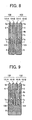
- one passage 500 includes a pressure chamber 501, a fluid resistance portion 502 serving as a liquid supply port for supplying liquid to the pressure chamber 501, and a liquid inflow portion 503.
- a plurality of passages 500 are arrayed at a given pitch in the direction in which nozzle orifices are arranged.
- the width (in the direction in which the passages 500 are arrayed) of a partition (hereinafter, "chamber partition”) 511 separating adjacent pressure chambers 501 is different from the width of a partition (hereinafter, “resistance partition”) 512 separating adjacent fluid resistance portions 502.
- the current density of a surrounding portion of each chamber 501 may significantly differ from the current density of a surrounding portion of each fluid resistance portion 502. Such a difference in the current density may cause a variation in the thickness of a coating film formed by electroforming. Consequently, a variation in height may be caused between the chamber partition 511 and the resistance partition 512.
- the width of the chamber partition 511 may be formed smaller than the width of the resistance partition 512.
- an adhesive agent may overflow into the fluid resistance portion 502 in greater amounts, which may cause failure in ejecting liquid droplets.
- a void such as a hole or concavity might be provided in the resistance partition 512.
- the width of the resistance partition 512 may need to be set relatively small in order to array orifices in relatively high density. Therefore, such a configuration may require a higher level of manufacturing technique or skill, which may not be actually implemented for forming such void in the resistance partition 512.
- EP 1 099 556 discloses an ink-jet head in which each of the pressure chambers and ink inlet passages are separated by partition walls that each have a plurality of adhesive receiving grooves.
- the present disclosure provides a liquid ejection head capable of recording a high-quality image with an increased density of liquid passages and nozzle orifices.
- a liquid ejection head is provided as specified in the claims.
- spatially relative terms such as “beneath”, “below”, “lower”, “above”, “upper” and the like may be used herein to facilitate description of one element or feature's relationship to another element(s) or feature(s) as illustrated in the figures. It will be understood that the spatially relative terms are intended to encompass different orientations of the device in use or operation in addition to the orientation depicted in the figures. For example, if the device in the figures is turned over, elements described as “below” or “beneath” other elements or features would then be oriented “above” the other elements or features. Thus, a term such as “below” can encompass both an orientation of above and below. The device may be otherwise oriented (rotated 90 degrees or at other orientations) and the spatially relative descriptors herein interpreted accordingly.
- first, second, etc. may be used herein to describe various elements, components, regions, layers, and/or sections, it should be understood that these elements, components, regions, layers, and/or sections should not be limited by these terms. These terms are used only to distinguish one element, component, region, layer, or section from another region, layer, or section. Thus, a first element, component, region, layer, or section discussed below could be termed a second element, component, region, layer, or section without departing from the teachings of the present disclosure.
- FIG. 2 is an exploded perspective view of a liquid ejection head according to an exemplary embodiment of the present disclosure.
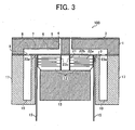
- FIG. 3 is a cross-sectional view of the liquid ejection head of FIG. 2 , taken along a long direction of a pressure chamber provided therein.
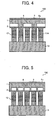
- FIG. 4 is a cross-sectional view illustrating a bi-pitch structure of the liquid ejection head of FIG. 2 , taken along a short direction of the pressure chamber.
- FIG. 5 is a cross-sectional view illustrating a normal-pitch structure of the liquid ejection head of FIG. 2 , taken along a short direction of the pressure chamber.
- a liquid ejection head 100 typically includes a passage plate 1, an orifice plate 2, a vibration plate 3, piezoelectric elements 12, a base member 13, FPC (flexible printed circuit) cables 15, and a frame member 17.
- the passage plate 1 is made of metal and serves as a passage forming member in which liquid passages including communication paths 5, pressure chambers 6, fluid resistance portions 7, and inflow portions 8 are typically formed.
- the orifice plate 2 is made of metal and serves as an orifice forming member in which orifices 4 are formed.
- the orifice plate 2 is also coupled to an upper surface of the passage plate 1.
- the vibration plate 3 is made of metal and is coupled to an undersurface of the passage plate 1 so as to form a wall surface of each pressure chamber 6.
- the pressure chambers 6, the flow resistance portions 7, and the inflow portions 8 are formed by the passage plate 1, the orifice plate 2, and the vibration plate 3.
- the orifices 4 through which droplets are ejected are in communication with corresponding pressure chambers 6 via the communication paths 5.
- the inflow portions 8 are in communication with the corresponding pressure chambers 6 via the fluid resistance portions 7.
- Liquid, e.g. ink, is stored in common chambers 10 that are formed in the frame member 17, described later, and is supplied to the respective inflow portions 8 through corresponding supply openings 9 that are formed in the vibration plate 3.
- the upper surfaces of laminated-type piezoelectric elements 12 serving as driving elements (actuators or pressure generators) are joined to the undersurface of the vibration plate 3 via connectors, not illustrated, formed at the vibration plate 3.
- the piezoelectric elements 12 are disposed below the corresponding pressure chambers 6. Further, the undersurfaces of the piezoelectric elements 12 are joined to the base member 13.
- Each piezoelectric element 12 includes a piezoelectric material layer 21, an internal electrode 22a, and an internal electrode 22b.
- the internal electrodes 22a and 22b are alternately laminated via the piezoelectric material layer 21.
- One end of the internal electrode 22a is extended to one side of the piezoelectric element 12 and is connected to a side electrode (external electrode) 23a
- one end of the internal electrode 22b is extended to another side of the piezoelectric element 12 and is connected to a side electrode 23b.
- the piezoelectric element 12 is displaced in a direction in which the internal electrodes 22a and 22b are laminated.
- the FPC cables 15 are connected to the piezoelectric elements 12 by solder bonding, ACF (anisotropic conductive film) bonding, or wire bonding.
- the FPC cables 15 are provided with a driving circuit or driving IC (integrated circuit), not illustrated, to selectively apply a drive pulse to each piezoelectric element 12.
- the liquid ejection head 100 may have what is called a "bi-pitch" structure, in which piezoelectric elements 12 and pillars 12A are alternately arranged in a latitudinal direction of the pressure chambers 6, that is, the direction in which the orifices 4 are arrayed (hereinafter also referred to as the orifice array direction).
- the piezoelectric elements 12 are located under the corresponding pressure chambers 6, while the pillars 12A are located below partition portions 6a between the pressure chambers 6.
- the piezoelectric elements 12 and the pillars 12A are substantially identical in configuration. However, the pillars 12A merely serve as support members because no driving voltage is applied thereto.
- the liquid ejection head 100 may have what is called a "normal pitch" structure, in which no such pillars 12A are provided and the piezoelectric elements 12 are located under the corresponding pressure chambers 6.
- the displacement of the piezoelectric elements 12 is generated in a given direction, thereby applying pressure to the ink in the pressure chambers 6.
- the liquid ejection head 100 ejects liquid droplets according to a side shooting method.
- the direction in which a recording liquid is ejected as liquid droplets is different from the direction in which the recording liquid flows through the pressure chamber 6 (hereinafter, may be referred to as "liquid flow direction").
- the size of liquid ejection head may significantly depend on the size of piezoelectric element. Accordingly, the miniaturization of the piezoelectric elements 12 may directly result in and facilitate the miniaturization of the liquid ejection head 100.
- the frame member 17 is joined to the outside of an actuator unit including the piezoelectric elements 12, the base member 13, and the FPC cables 15.
- the frame member 17 is made of epoxy system resin or polyphenylene sulphite and is formed by injection molding.
- the common chambers 10 are formed together with corresponding supply ports 19.
- Each supply port 19 is connected to an external liquid source, such as a sub-reservoir and a recording liquid cartridge, not illustrated, for supplying a recording liquid from the external liquid source to the corresponding common chamber 10.
- the passage plate 1, the orifice plate 2, and the vibration plate 3 are formed by nickel electroforming.
- the passage plate 1 has a groove section including penetration holes serving as the communication paths 5, the pressure chambers 6, the fluid resistance portions 7, and the inflow portions 8.
- the pressure chambers 6 are separated from each other by the partition portions 6a.
- the orifice plate 2 has nozzle orifices serving as the orifices 4. Each orifice 4 is formed to have a diameter of, for example, approximately 10 ⁇ m to approximately 35 ⁇ m.
- the orifice plate 2 is joined to the passage plate 1 with an adhesive.
- the liquid ejection surface of the orifice plate 2 on the side opposite the side of the pressure chamber 6 is subjected to water-repellent processing.
- the vibration plate 3 has thin portions corresponding to the pressure chambers 6 to facilitate deformation thereof. At the central portions of respective thin portions, connectors (not illustrated) are provided to join the piezoelectric elements 12.
- a laminated-type piezoelectric-element member coupled to the base member 13 is grooved with a dicing saw, for example, and divided into individual piezoelectric elements 12.
- the pillars 12A are produced from the laminated-type piezoelectric-element member by the groove forming process.
- the pillars 12A merely serve as support members because no driving voltage is applied thereto.
- the liquid ejection head 100 thus constructed may be driven according to any suitable driving method, for example, by what is called a "push-ejection" method.
- a control unit selectively applies a driving pulse having a voltage of from 20 V to 50 V to an appropriate piezoelectric element 12 according to an image to be recorded.
- the driving pulse causes displacement of the piezoelectric element 12 and the vibration plate 3 is deformed toward the orifice plate 2.
- the volume of the pressure chamber 6 is changed so that pressure is applied to the liquid in the pressure chamber 6.
- the liquid is ejected as droplets from the orifices 4 of the orifice plate 2.
- Such liquid ejection reduces the pressure in the pressure chamber 6, thereby generating a flow of the liquid into the pressure chamber 6.
- the inertia of the liquid flow further generates a slight amount of negative pressure in the pressure chamber 6.
- the liquid ejection head 100 may be driven according to what is called a "pull-and-release ejection" method.
- the vibration plate 3 is pulled and then released to apply pressure to the liquid in the pressure chamber 6.
- Such a pull-and-release ejection method utilizes the restoring force of the vibration plate 3 to eject a liquid droplet from the liquid ejection head 100.
- the liquid ejection head 100 may be driven according to what is called a "pull-and-push ejection" method.
- the vibration plate 3 is pulled and then is positively pushed to apply pressure to the liquid in the pressure chamber 6.
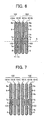
- FIG. 6 is a plan view illustrating a passage pattern formed at a passage plate (or passage plate member) of the liquid ejection head.
- a liquid ejection head 100 includes passages 101A and 101B.
- Each of the passages 101A and 101B typically includes a pressure chamber 6 being in communication with orifices 4, a fluid resistance portion 7 having a width smaller than the width of the pressure chamber 6, and an inflow portion 8.
- the width of the pressure chamber 6 refers to the length thereof in the orifice array direction of a passage plate 1.
- the width of the pressure chamber 6 is used in the same manner unless explicitly noted.
- the two adjacent passages 101A and 101B form one passage group 102.
- a given number of passages 101A and 101B are arranged in the orifice array direction to form a plurality of the passage groups 102 as illustrated in FIG. 6 .
- any suitable number of the passage groups 102 may be arranged corresponding to the number of orifices 4. This point similarly applies to the drawings described herein below.
- the pitch between the adjacent pressure chambers 6 of each passage group 102 is set to be substantially equal to the pitch between the adjacent pressure chambers 6 of the adjacent passage groups 102.
- each passage 101A is disposed to the left side thereof, and the fluid resistance portion 7 of each passage 101B is disposed to the right side thereof.
- a relatively wide partition portion 7a is provided between the two fluid resistance portions 7.
- a void 103 is formed in each partition portion 7a but no such void 103 is formed in the partition portion 7b between the two adjacent passage groups 102.
- the void 103 may be a penetration hole passing through the thickness of the passage forming member.
- the void 103 may be a blind hole or a concavity having a bottom surface inside the passage forming member.
- the void 103 may be formed in any other suitable shape besides those described herein.
- the widths of the partition portions 6a, 6b, 7a, and 7b are set to be substantially identical. Further, the partition portion 6b and the partition portion 7b form a linear shape together as illustrated in FIG. 6 , which shows a plan view.
- the fluid resistance portions 7, the partition portions 7a having the voids 103 formed by penetrating or partially removing the passage plate member, and the partition portions 7b not having the voids 103 are arrayed on a line X-X extending in the direction in which the plurality of passages are arrayed (hereinafter also referred to as "passage array direction").
- the passage patterns according to the later-described exemplary embodiments illustrated in FIG. 7 through FIG. 20 have a similar configuration along a line X-X as illustrated in FIG. 6 , and thus the illustration and description of the line X-X are omitted hereinafter for simplicity.
- the partition portions separating the fluid resistance portions 7 include the partition portion 7a having the void 103 and the partition portion 7b not having the void 103.
- the above-described configuration provides a liquid ejection head with a higher-density passage group and a void that is formed between the fluid resistance portions of each passage group so as to adjust the width of partition portion and/or receive an overflow of excess adhesive.
- the adjacent passages form one passage group.
- a given number of passages are arrayed in the orifice array direction to form a plurality of the passage groups.
- the partition portion between the adjacent passages of each passage group is provided with a void whereas the partition portion between the adjacent passage groups is provided without the void.
- the width of the partition portion between the adjacent fluid resistance portions of each passage group is adjustable so that the void may be formed in the partition portion and accommodate adhesive overflow to prevent bonding failure of the passage plate.
- the width of the partition portion between the fluid resistance portions is set equal to the width of the partition portion between the pressure chambers.
- a void is formed between the adjacent fluid resistance portions of each passage group whereas such a void is not formed between the adjacent fluid resistance portions of the adjacent passage groups. Accordingly, the respective passages of each passage group have different shapes.
- the pitch between the adjacent pressure chambers of the single passage group is set to be equal to the pitch between the adjacent pressure chambers of the adjacent passage groups.
- Such a configuration provides a uniform electric-field distribution around passages when the passages are formed by electroforming, etching, or any other suitable manufacturing method.
- the pitch between the adjacent pressure chambers of each passage group is set to be equal to the pitch between the adjacent pressure chambers of the adjacent passage groups.
- a void is formed between the fluid resistance portions of each passage group.
- a void is formed at the partition portion between the fluid resistance portions, in which the cross-sectional areas of the respective passages are relatively small and the width of the partition portion therebetween is relatively great.
- the width of the partition portion between the adjacent pressure chambers of each passage group is set to be substantially equal to the width of the partition portion between the fluid resistance portion and the void.
- Such a configuration provides a uniform electric-field distribution around passages when the passages are formed by electroforming, etching, or any other suitable manufacturing method. As a result, unevenness in height between the partition portions formed by the electroforming method or the like is reduced.
- any other suitable processing for aligning the heights of the partition portions may be omitted, resulting in a reduction of the number of steps in the manufacturing process.
- the partition portions between passage groups i.e., the partition portion 6b and the partition portion 7b are formed together to have a linear shape along the liquid flow direction of the passage.
- Such a configuration also provides a uniform electric-field distribution around each passage, and thus a uniform thickness of the passage plate when the passages are formed by the electroforming method or the like.
- the passages are formed by an electroforming method
- electric current may concentrate on a conductor portion having a higher curvature.
- the electric-field density generated around such a high-curvature conductor portion may become relatively high.
- the electric-field density thereof should be kept as uniform as possible, and the line patterns in the electroforming should be as straight as possible.
- the partition portion between the adjacent passage groups is formed in a linear shape so that a uniform electric-field distribution is obtained around the partition portion.
- a uniform thickness is obtained for the passage plate formed by the electroforming method.
- the voids may form a considerably minute pattern.
- Such a configuration may increase the degree of difficulty in forming the partition portions and thus the incidence of failure in their formation. Also, such a configuration may generate an increased electric-field density around each void due to a high degree of concentration of the minute pattern. As a result, the partition portions between the fluid resistance portions may be undesirably formed in relatively great height compared to other partition portions.
- each passage has a planar shape asymmetrical about a lengthwise center line Y1 of the liquid passage.
- the passage group has a planer shape symmetrical about a lengthwise center line Y2 of the passage group.
- a void is formed between the fluid resistance portions of each passage group whereas no such void is formed between the fluid resistance portions of the adjacent passage groups.
- a relatively large area is allocated to form the void.
- an increase in the size of void reduces the degree of concentration of the electric field around the fluid resistance portions.
- all the portions constituting the passage are formed with an identical member or material.
- the passage including a pressure chamber, a fluid resistance portion, and a void is formed with an identical passage-forming member, high-precision bonding processing for bonding a plurality of passage-forming members may be omitted. As a result, the number of steps in the manufacturing and assembly process of the liquid ejection head can be reduced.
- one passage may be formed with a plurality of passage-forming members.
- high-precision bonding processing needs to be carried out while applying adhesive to respective surfaces of the plurality of passage-forming members.
- Such application of adhesive to the plurality of members may increase the amount of adhesive overflowing the bonding surface or surfaces thereof.
- the void serving as a receiving portion of such adhesive overflow is formed at the partition portion having a relatively large area between the fluid resistance portions.
- FIG. 7 is a plan view illustrating a passage pattern formed in a passage plate of the liquid ejection head.
- a liquid ejection head 100 includes a plurality of passage groups 102.
- Each passage group 102 further includes passages 101A, 101B, and 101C.
- Each of the passages 101A, 101B, and 101C typically includes a pressure chamber 6 being communicated with orifices 4, a fluid resistance portion 7 having a width smaller than the width of the pressure chamber 6, and an inflow portion 8.
- a given number of passages 101A, 101B, and 101C are arranged in the orifice array direction to form a plurality of passage groups 102.
- the passages 101A, 101B, and 101C are also arranged so that the pitch between the adjacent pressure chambers 6 of each passage group 102 is equal to the pitch between the adjacent pressure chambers 6 of the adjacent passage groups 102.
- the passages 101A, 101B, and 101C are arranged so that the width of the partition portion 6a may be equal to the width of the partition portion 6b.
- the fluid resistance portion 7 of the passage 101A is disposed to the left side thereof
- the fluid resistance portion 7 of the passage 101B is disposed to the central portion thereof
- the fluid resistance portion 7 of the passage 101C is disposed to the right side thereof.
- a relatively wide partition portion 7a may be obtained between the fluid resistance portion 7 of the passage 101B and each of the fluid resistance portions 7 of the passages 101A and 101C.
- a void 103 is formed by penetrating or partially removing the passage forming member.
- the void 103 is not formed in the partition portion 7b between the adjacent passage groups 102.
- Partition portions 6a are formed between the three adjacent pressure chambers of each passage group 102 and a partition portion 6b is formed between the adjacent passage groups 102. Further, as described above, the partition portion 7a is formed between the fluid resistance portion 7 and the void 103 and the partition portion 7b is formed between the fluid resistance portions 7 of the adjacent passage groups 102.
- the partition portions 6a, 6b, 7a, and 7b are formed to have a substantially identical width.
- the width of the partition portion between the adjacent pressure chambers of each passage group, the width of the partition portion between the adjacent pressure chambers of the adjacent passage groups, and the width of the partition portion between the fluid resistance portion and the void are formed to be substantially identical.
- a uniform thickness is obtained for the passage forming member, and thus the amount of adhesive overflowing the bonding surface can be reduced.
- the maximum possible width of the fluid resistance portion 7 is relatively small compared to the exemplary embodiment illustrated in FIG. 6 .
- FIG. 8 is a plan view illustrating a passage pattern formed in a passage plate of the liquid ejection head.
- the passage pattern of FIG. 8 is similar in configuration to the passage pattern of FIG. 6 . However, in FIG. 8 , respective inflow portions of passage 101A and passage 101B forming each passage group 102 are in communication with each other and are integrally formed by providing one inflow portion 8.
- FIG. 9 is a plan view illustrating a passage pattern formed in a passage plate of the liquid ejection head.
- the passage pattern of FIG. 9 is similar in configuration to the passage pattern of FIG. 6 . However, in FIG. 9 , respective inflow portions of passages 101A and the passages 101B forming two adjacent passage groups 102 are in communication with each other and are integrally formed by providing one inflow portion 8.
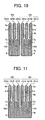
- FIG. 10 is a plan view illustrating a passage pattern formed in a passage plate of the liquid ejection head.
- the passage pattern of FIG. 10 is similar in configuration to the passage pattern of FIG. 7 . However, in FIG. 10 , respective inflow portions of passages 101A, 101B, and 101C forming each passage group 102 are in communication with each other and are integrally formed by providing one inflow portion 8.
- FIG. 11 is a plan view illustrating a passage pattern formed in a passage plate of the liquid ejection head.
- the passage pattern of FIG. 11 is similar in configuration to the passage pattern of FIG. 7 . However, in FIG. 11 , respective inflow portions of passages 101A, 101B, and 101C forming two adjacent passage groups 102 are in communication with each other and are integrally formed by providing one inflow portion 8.
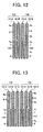
- FIG. 12 is a plan view illustrating a passage pattern formed in a passage plate of the liquid ejection head.
- the passage pattern of FIG. 12 is similar in configuration to the passage pattern of FIG. 6 . However, in FIG. 12 , respective inflow portions 8 of passages 101A and 101B forming each passage group 102 are in communication with corresponding liquid-supply portions, not illustrated.
- FIG. 13 is a plan view illustrating a passage pattern formed in a passage plate of the liquid ejection head.
- the passage pattern of FIG. 13 is similar in configuration to the passage pattern of FIG. 7 . However, in FIG. 13 , respective inflow portions 8 of passages 101A, 101B, and 101C forming each passage group 102 are in communication with corresponding liquid-supply portions, not illustrated.
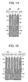
- FIG. 14 is a plan view illustrating a passage pattern formed in a passage plate of the liquid ejection head.
- the passage pattern of FIG. 14 is similar in configuration to the passage pattern of FIG. 7 .
- respective inflow portions of passages 101A and passages 101B forming two adjacent passage groups 102 are in communication with each other and are integrally formed by providing one inflow portion 8.
- voids 103 are in communication with the inflow portion 8.
- Pressure chambers 6 and fluid resistance portions 7 may have relatively great influence on the ejection properties of a liquid ejection head. Hence, similar to the passage pattern of FIG. 7 , the pressure chambers 6 or the fluid resistance portions 7 in FIG. 14 are separated from each other. However, in FIG. 14 , the fluid resistance portions 7 are in communication with a liquid-supply portion through the integrated inflow portion 8. Further, as described above, the voids 103 are also in communication with the integrated inflow portion 8.
- the passage pattern of FIG. 14 is advantageous from a manufacturing standpoint in that the separation of resist is easier to carry out when the passage pattern is formed by electroforming.
- FIG. 15 is a plan view illustrating a passage pattern formed in a passage plate of the liquid ejection head.
- the passage pattern of FIG. 15 is similar in configuration to the passage pattern of FIG. 7 .
- respective inflow portions of passages 101A, 101B, and 101C forming two adjacent passage groups 102 are in communication with each other and are integrally formed by providing one inflow portion 8.
- voids 103 of the passage groups 102 are also in communication with the inflow portion 8.
- Pressure chambers 6 and fluid resistance portions 7 may have relatively great influence on the ejection properties of the liquid ejection head. Hence, similar to the passage pattern of FIG. 7 , the pressure chambers 6 or the fluid resistance portions 7 are separated from each other in the passage pattern of FIG. 15 . However, in FIG. 15 , the fluid resistance portions 7 are in communication with a liquid-supply portion through the inflow portion 8. Further, as described above, the voids 103 are also in communication with the inflow portion 8.
- the passage pattern of FIG. 11 is advantageous in that the separation of resist is easier to accomplish when the passage pattern is formed by electroforming.
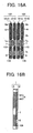
- FIG. 16A is a plan view illustrating a passage pattern formed in a passage plate of the liquid ejection head.
- FIG 16B is a cross-sectional side view of the passage plate of FIG. 16A .
- a passage plate 1 is formed of two plate-forming members 1A and 1B as illustrated in FIG. 16B .
- a pressure chamber 6 includes a penetration portion 6A formed in the plate member 1A and a penetration portion 6B formed in the plate member 1B.
- a fluid resistance portion 7 includes a penetration portion formed in the plate member 1B.
- An inflow portion 8 includes a penetration portion formed in the plate member 1A.
- a liquid-supply portion 109 provided corresponding to the inflow portion 8 includes a penetration hole formed in the plate member 1B.
- the fluid resistance portion 7 in the plate member 1B is formed to have a height, a width, and a cross-sectional area of hollow portion smaller than a height, a width, and a cross-sectional area of the pressure chamber 6.
- Respective inflow portions 8 of passages 101A and 101B forming two adjacent passage groups 102 are separated from each other.
- FIGS. 16A and 16B the portions formed in the plate member 1A are indicated by right-leaning hatching, the portions formed in the plate member 1B are indicated by left-leaning hatching, and the overlapping areas of the respective portions of the plate members 1A and 1B are indicated by cross-hatching.
- the liquid ejection head includes passages 101A and 101B.
- Each of the passages 101A and 101B typically includes the pressure chamber 6, the fluid resistance portion 7 that supplies liquid to the pressure chamber 6 and has a width smaller than the width of the pressure chamber 6, and the inflow portion 8.
- the adjacent two passages 101A and 101B form one passage group 102.
- a given number of passages 101A and 101B are arranged in the orifice array direction to form a plurality of the passage groups 102.
- the passages 101A and 101B are also arranged so that the pitch between the adjacent pressure chambers 6 of each passage group 102 may be equal to the pitch between the adjacent pressure chambers 6 of the adjacent passage groups 102.
- the passages 101A and 101B are arranged so that the width of the partition portion 6a may be equal to the width of the partition portion 6b.
- the fluid resistance portion 7 of each passage 101A is disposed to the left side thereof and the fluid resistance portion 7 of each passage 101B is disposed to the right side thereof.
- a relatively wide partition portion 7a is obtained between the fluid resistance portions 7 of the passage 101A and 101B.
- a void 103 may be formed in a portion of the plate member 1A corresponding to each partition portion 7a.
- the void 103 may be formed in portions of the plate members 1A and 1B corresponding to each partition portion 7a.
- the void 103 is not formed in the partition portion 7b between the two adjacent passage groups 102.
- a plurality of voids 103 may be formed at different plate members so as to securely obtain a receiving portion of the adhesive that might overflow the bonding surfaces when the plate-forming members 1A and 1B are joined together. Further, the use of a plurality of plate-forming members enables a configuration in which such voids are spaced apart from the fluid resistance portions.
- FIG. 17A is a plan view illustrating a passage pattern formed in a passage plate of the liquid ejection head.
- FIG 17B is a cross-sectional side view of the passage plate of FIG. 17A .
- FIGS. 17A and 17B The passage pattern of FIGS. 17A and 17B is similar in configuration to that of FIGS. 16A and 16B . However, in FIGS. 17A and 17B , respective liquid-supply portions of two adjacent passage groups 102 are in communication with each other and are integrally formed by providing one liquid-supply portion 109 having an increased area.
- FIG. 18A is a plan view illustrating a passage pattern formed in a passage plate of the liquid ejection head.
- FIG. 18B is a cross-sectional side view of the passage plate of FIG. 18A .
- each inflow portion 8 includes a penetration portion 8A formed in a plate member 1A and a penetration portion 1B formed in a plate member 1B, and thus has a relatively great depth compared to the inflow portion 8 of FIGS. 16A and 16B .
- the respective inflow portions 8 of passages 101A and 101B are separated from each other so that the fluid resistances thereof are reduced. In this case, a liquid-supply portion is provided to any other suitable member.
- FIG. 19A is a plan view illustrating a passage pattern formed in a passage plate of the liquid ejection head.
- FIG. 19B is a cross-sectional side view of the passage plate of FIG. 19A .
- the passage pattern of FIG. 19A and 19B is similar in configuration to the passage pattern of FIG. 18A and 18B .
- a penetration portion 8C is formed in a plate member 1B so as to extend between a plurality of passage groups 102.
- the passages 101A and 101B of the plurality of passage groups 102 are partially in communication with each other through the inflow portions 8.
- FIG. 20 is a plan view illustrating a passage pattern formed in a passage plate of the liquid ejection head.
- the passage pattern of FIG. 20 is similar in configuration to the passage pattern of FIG. 15 . However, in the passage pattern of FIG. 20 , a plurality of voids 103 are formed in each partition portion 7a. Such a configuration increases the rigidity of the partition portion 7a.
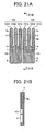
- FIG. 21A is a plan view of the above-described passage pattern of FIG. 10 and FIG. 21B is a cross-sectional side view of FIG. 21A .
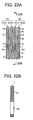
- FIG. 22A is a plan view of the above-described passage pattern of FIG. 12 and FIG. 22B is a cross-sectional side view of FIG. 22A .
- the partition portion 7a has one end integrally formed with the plate member 1, and the other end (on the side of the inflow portion 8) separated from the plate member 1 (hereinafter, "single-end support structure").
- the void 103 may be formed to have a bottom as illustrated in FIG. 21B by performing half-etching on the plate member 1.
- the partition portion 7a has both ends integrally formed with the plate member 1 (hereinafter, "double-end support structure"), and thus may obtain a relatively high strength and/or rigidity.
- the void 103 is formed to penetrate the plate member 1 as illustrated in FIG. 22B by performing full-etching on the plate member 1.
- the void 103 may be preferably formed in a different shape corresponding to whether the partition portion 7a has a single-end support structure or a double-end support structure.
- the fluid resistance portions are arrayed in one row in the passage array direction.
- the present disclosure is also applicable to a liquid ejection head having a configuration in which fluid resistance portions are arrayed in a plurality of rows in the direction in which liquid flows through the passage.
- FIG. 23 is a plan view illustrating a passage pattern formed in a passage plate of the liquid ejection head.
- one passage group 102 includes a passage 101A and a passage 101B.
- Each of the passages 101A and 101B includes a fluid resistance portion 7 between a pressure chamber 6 and an inflow portion 8.
- the fluid resistance portion 7 further includes a first fluid-resistance area 7A and a second fluid-resistance area 7B.
- the first fluid-resistance area 7A has one end in communication with the pressure chamber 6 and the other end in communication with one end of the second fluid-resistance area 7B.
- the other end of the second fluid-resistance area 7B is in communication with the inflow portion 8.
- a partition portion 7c is formed to partition the adjacent fluid resistance portions 7 of each passage group 102.
- the partition portion 7c has a void 103 between the first fluid-resistance areas 7A of each passage group 102, and does not have a void 103 between the second fluid-resistance areas 7B thereof.
- a partition portion 7d is formed to partition the adjacent fluid resistance portions 7 of the adjacent passage groups 102.
- the partition portion 7d does not have a void 103 between the first fluid-resistance areas 7A of the adjacent passage groups 102, and has a void 103 between the second fluid-resistance areas 7B thereof.
- each of the partition portions 7c and 7d includes a portion having the void 103 and a portion not having the void 103.
- a partition portion 6c is formed between pressure chambers 6 of each passage group 102.
- Each partition portion 6c is integrally connected to the partition portion 7c and is configured to separate the pressure chambers 6.
- a partition portion 6d is formed between pressure chambers 6 of adjacent passage groups 102.
- the partition portion 6d is integrally connected to the partition portion 7d and is configured to separate the pressure chambers 6 of adjacent passage groups 102.
- a higher-density liquid ejection head is provided with a void serving as a receive portion for adhesive that might overflow the bonding surface of the passage plate. Further, an increase in the lengths of the fluid resistance portions may increase the fluid resistances thereof.
- FIG. 24 is a plan view illustrating a passage pattern formed in a passage plate of the liquid ejection head.
- the passage pattern of FIG. 24 is similar in configuration to the passage pattern of FIG. 23 . However, in the passage pattern of FIG. 24 , voids 103 corresponding to second fluid-resistance areas 7B are integrally formed with an inflow portion 8.
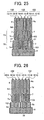
- FIG. 25 is a plan view illustrating a passage pattern formed in a passage plate of the liquid ejection head.
- the passage pattern of FIG. 25 is similar in configuration to the passage pattern of FIG. 23 . However, in FIG. 25 , fluid resistance portions 7 of a plurality of passage groups 102 are in communication with each other at the boundary between the first fluid-resistance portions 7A and the second fluid-resistance portions 7B through communication portions 37.
- FIG. 26 is a plan view illustrating a passage pattern formed in a passage plate of the liquid ejection head.
- fluid resistance portions 7 of a plurality of passage groups 102 are arrayed in one row in the direction in which passages 101A, 101B, and 101C are arrayed. As illustrated in FIG. 26 , two adjacent fluid-resistance portions 7 in each passage group 102 are in communication with an inflow portion 8 through a portion 8a thereof. Further, the three fluid-resistance portions 7 in each passage group 102 are in communication with each other through a communication portion 38.
- the passage plate, the orifice plate, and the vibration plate are configured as separate members.
- passage plate and the orifice plate may be integrally formed as a single member, or the passage plate and the vibration plate may be integrally formed as a single member.
- a liquid ejection head according to the above-described exemplary embodiments takes the form of a piezoelectric liquid-ejection head
- a liquid ejection head according to an exemplary embodiment of the present disclosure is applicable to a thermal liquid-ejection head using an electricity-to-heat converter or any other suitable type of liquid ejection head.
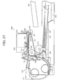
- FIGS. 27 and 28 an image forming apparatus including a liquid ejection device with a liquid ejection head according to an exemplary embodiment of the present disclosure is described with reference to FIGS. 27 and 28 .
- FIG. 27 is a schematic view illustrating a general configuration of a mechanical section of the image forming apparatus.
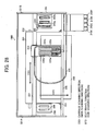
- FIG. 28 is a plan view illustrating relevant portions of the mechanical section of FIG. 27 .
- an image forming apparatus 1000 may be configured as a serial-type image forming apparatus.
- a carriage 233 is slidably supported by a primary guide rod 231 and a secondary guide rod 232 extending between side plates 221A and 221B.
- the carriage 233 is driven by a main scanning motor to move in carriage travel directions (main scanning directions) indicated by a double arrow CSD in FIG. 28 .
- a recording head assembly 234 including two recording heads 234a and 234b.
- Each of the recording heads 234a and 234b is formed of a liquid ejection head according to an exemplary embodiment of the present disclosure.
- the recording heads 234a and 234b are configured to eject yellow (Y), cyan (C), magenta (M), and black (K) inks.
- Y yellow
- C cyan
- M magenta
- K black
- the recording heads 234a and 234b are also mounted to the carriage 233 so that ink droplets are ejected downward.
- Each of the recording heads 234a and 234b may include two columns of orifices, for example.
- the recording head 234a may have one column of orifices configured to eject ink droplets of K and the other column of orifices configured to eject ink droplets of C
- the recording head 234b may have one column of orifices configured to eject ink droplets of M and the other column of orifices configured to eject ink droplets of Y.
- ink reservoirs 235a and 235b configured to store and supply respective color inks to the corresponding columns of orifices of the recording heads 234a and 234b.
- the respective color inks may be supplied and refilled from ink cartridges 210K, 210C, 210M, and 210Y to the ink reservoirs 235a and 235b through corresponding ink-supply tubes 236.
- the image forming apparatus 1000 further includes a sheet feed section configured to feed sheets 242 stacked on a sheet stack portion or platen 241 of a sheet tray 202.
- the sheet feed section may include a sheet feeding roller 243 to separate and feed the sheets 242 one by one from the sheet stack portion 241, and a separating pad 244 facing the sheet feeding roller 243 and made of a material having a relatively high coefficient of friction.
- the separating pad 244 is also configured to be biased toward the sheet feeding roller 243.
- the image forming apparatus 1000 further includes a sheet conveyance section configured to convey the sheet 242, fed from the sheet feed section, under the recording head assembly 234.
- the sheet conveyance section may include a guide member 245 configured to guide the sheet 242, a counter roller 246, a conveyance guide member 247, a front-edge pressing member 248 having a front-edge pressing roller 249, and a conveyance belt 251 serving as a conveyor configured to convey the sheet 242, fed from the sheet feed section, to an area under the recording head assembly 234 while attracting the sheet 242 thereon by an electrostatic force.
- the conveyance belt 251 may be formed in an endless shape as illustrated in FIG. 27 .
- the conveyance belt 251 is extended between a conveyance roller 252 and a tension roller 253 so as to rotate in the belt travel direction (sub-scanning direction) indicated by the arrow BTD in FIG. 28 .
- the sheet conveyance section may further include a charging roller 256.
- the charging roller 256 is disposed in contact with the outer surface of the conveyance belt 251 so as to be rotationally driven by the rotation of the conveyance belt 251.
- the conveyance belt 251 rotationally moves in the belt travel direction when the conveyance roller 252 is rotationally driven by a sub-scanning motor via a timing belt and a timing roller.
- the image forming apparatus 1000 includes a sheet eject section configured to eject the sheet 242 having an image recorded by the recording head assembly 234 thereon.
- the sheet eject section may include a separating claw 261 configured to separate the sheet 242 from the conveyance belt 251, sheet ejecting rollers 262 and 263, and a catch tray 203 disposed below the sheet ejecting roller 262.
- a duplex sheet-feeding unit 271 may be detachably attached to the back of the image forming apparatus.
- the duplex sheet-feeding unit 271 receives the sheet 242 sent by the rotation of the conveyance belt 251 in a direction opposite to the belt travel direction Y in FIG. 28 , conveys the sheet 242 in such a manner that the sheet 242 is turned upside down, and feeds the sheet 242 back between the counter roller 246 and the conveyance belt 261.
- a manual sheet-feeding tray 272 may be provided at the top of the duplex sheet-feeding tray 271.
- a servicing unit 281 may be disposed at a non-printing area on one side in the carriage travel direction CSD to maintain and restore the orifices of the recording head assembly 234 in and to good condition.
- the servicing unit 281 may include cap members 282a and 282b configured to cover the respective orifice surfaces of the recording heads 234a and 234b, a wiper 283 configured to wipe or clean the orifice surfaces of the recording heads 234a and 234b, and an ink-receiving member 284 configured to receive ink droplets ejected from the orifices in what is called a "dummy-ejecting" operation. In such a dummy-ejecting operation, ink droplets are ejected for maintaining and/or restoring the orifices in good condition, not for forming an image.
- an ink-receiving unit 288 serving as a container configured to receive ink droplets from the orifices in a dummy-ejecting operation in which, during an image forming operation, ink droplets are ejected for maintaining and/or restoring the orifices in good condition, not for forming an image.
- the ink-receiving unit 288 includes openings 289 arranged in the orifice array direction of each of the recording head 234a and 234b.
- a sheet 242 is separated one by one from the sheet-feed tray 202, is fed upward in a substantially vertical direction, is guided by the guide member 245, and is conveyed while being sandwiched between the conveyance belt 251 and the counter roller 246.
- the front edge of the sheet 242 is also guided by the conveyance guide member 247, and is pressed by the front-edge pressing roller 249 toward the conveyance belt 251.
- the sheet 242 is forced to turn the conveyance direction by approximately 90 degrees.
- the charging roller 256 is applied with alternate voltages so that positive and negative outputs are alternately repeated.
- an alternating charge-voltage pattern that is, a band-shape charge pattern in which positive and negative polarities are alternately charged at a given width in the sub-scanning direction BTD.
- the recording head assembly 234 is driven based on image signals while the carriage 233 is being moved.
- the recording head assembly 234 ejects ink droplets onto the sheet 242 to record one line of a target image.
- the image forming apparatus 1000 starts an operation of recording another line of the target image.
- the image forming apparatus 1000 ends the image forming operation, and ejects the sheet 242 to the catch tray 203.
- the image forming apparatus 1000 is provided with a liquid ejection head according to an exemplary embodiment of the present disclosure.
- the image forming apparatus 1000 may steadily provide a high-quality image with a high-density liquid ejection head.
- the image forming apparatus 1000 is described in the context of a printer.
- an image forming apparatus according to an exemplary embodiment of the present disclosure is not limited to such a printer, but may take the form of any other suitable type of image forming apparatus, such as a copier, a facsimile machine, or a multi-functional printer including functions thereof.
- an image forming apparatus may take the form of any other suitable type of image forming apparatus using a resist, a DNA sample, or a recording liquid other than ink.
- Embodiments of the present disclosure may be conveniently implemented using a conventional general purpose digital computer programmed according to the teachings of the present specification, as will be apparent to those skilled in the computer art.
- Appropriate software coding can readily be prepared by skilled programmers based on the teachings of the present disclosure, as will be apparent to those skilled in the software art.
- Embodiments of the present disclosure may also be implemented by the preparation of application specific integrated circuits or by interconnecting an appropriate network of conventional component circuits, as will be readily apparent to those skilled in the art.
- any one of the above-described and other exemplary features of the present disclosure may be embodied in the form of an apparatus, method, system, computer program, or computer program product.
- the aforementioned methods may be embodied in the form of a system or device, including, but not limited to, any of the structures for performing the methodology illustrated in the drawings.
- any of the aforementioned methods may be embodied in the form of a program.
- the program may be stored on a computer readable medium and configured to perform any one of the aforementioned methods when run on a computer device (a device including a processor).
- the storage medium or computer readable medium can be configured to store information and interact with a data processing facility or computer device to perform the method of any of the above-described embodiments.
- the storage medium may be a built-in medium installed inside a computer device main body or a removable medium arranged so that it can be separated from the computer device main body.
- Examples of the built-in medium include, but are not limited to, rewriteable non-volatile memories, such as ROMs and flash memories, and hard disks.
- the removable medium examples include, but are not limited to, optical storage media (such as CD-ROMs and DVDs), magneto-optical storage media (such as MOs), magnetic storage media (including but not limited to floppy diskettes, cassette tapes, and removable hard disks), media with a built-in rewriteable non-volatile memory (including but not limited to memory cards), and media with a built-in ROM (including but not limited to ROM cassettes), etc.
- optical storage media such as CD-ROMs and DVDs
- magneto-optical storage media such as MOs
- magnetic storage media including but not limited to floppy diskettes, cassette tapes, and removable hard disks
- media with a built-in rewriteable non-volatile memory including but not limited to memory cards
- ROM cassettes including but not limited to ROM cassettes
Landscapes
- Particle Formation And Scattering Control In Inkjet Printers (AREA)
Claims (10)
- Flüssigkeitsausstoßkopf, der aufweist:eine Vielzahl von Öffnungen bzw. Düsen (4), die konfiguriert sind, um Flüssigkeitströpfchen auszustoßen;eine Vielzahl von Kammern (6), die in Kommunikation bzw. Verbindung mit der Vielzahl von Öffnungen bzw. Düsen (4) sind;eine Vielzahl von Fluidwiderstandsabschnitten (7), die in Kommunikation mit der Vielzahl von Kammern (6) sind, wobei jeder Fluidwiderstandabschnitt von der Vielzahl von Widerstandsabschnitten eine schmälere bzw. kleinere Breite aufweist als eine Breite von jeder Kammer von der Vielzahl der Kammern;eine Vielzahl von Flüssigkeitspassagen (101A, 101B, 101C), wobei jede Flüssigkeitspassage von der Vielzahl der Flüssigkeitspassagen aus bzw. durch zumindest eine Kammer (6) von der Vielzahl von Kammern und zumindest einem Fluidwiderstandsabschnitt (7) von der Vielzahl von Fluidwiderstandsabschnitten ausgebildet ist;die Flüssigkeitspassagen (101A, 101B, 101C) in einer Vielzahl von Passagengruppen (102) angeordnet sind, die in einer Richtung angeordnet bzw. aufgestellt sind, wobei jede Passagengruppe von der Vielzahl von Passagengruppen angrenzende Flüssigkeitspassagen (101A, 101B, 101C) von der Vielzahl von Flüssigkeitspassagen einschließt; und der Flüssigkeitsausstoßkopf aufweist:eine Vielzahl von ersten Partitionen (7a), wobei jede erste Partition von der Vielzahl von ersten Partitionen konfiguriert ist, um die angrenzenden Flüssigkeitspassagen (101A, 101B, 101C) von jeder von der Vielzahl von Passagengruppen (102) zu separieren bzw. zu trennen; undeine Vielzahl von zweiten Partitionen (7b), wobei jede zweite Partition von der Vielzahl von zweiten Partitionen konfiguriert ist, um angrenzende Passagengruppen (102) von der Vielzahl von Passagengruppen (102) zu separieren bzw. zu trennen;dadurch gekennzeichnet, dass die erste Partition (7a) mit einer Lücke bzw. einem Loch (103) bereitgestellt ist und die zweite Partition (7b) nicht mit einer Lücke bzw. einem Loch bereitgestellt ist.
- Flüssigkeitsausstoßkopf nach Anspruch 1, wobei ein Abstand von angrenzenden Kammern (6) von der Vielzahl von Kammern in jeder der Passagengruppen (102) im Wesentlichen identisch zu bzw. mit einem Abstand von angrenzenden Kammern von der Vielzahl von Kammern zwischen angrenzenden Passagengruppen von den Passagengruppen (102) ist.
- Flüssigkeitsausstoßkopf nach Anspruch 1 oder 2, wobei die Lücke bzw. das Loch (103) von jeder der ersten Partitionen (7a) zwischen der Vielzahl von Fluidwiderstandsabschnitten (7) angeordnet ist.
- Flüssigkeitsausstoßkopf nach Anspruch 3, wobei eine Breite von jedem der ersten Partitionen (6a) zwischen der Vielzahl von Kammern (6), eine Breite von jeder der zweiten Partitionen (6b) zwischen der Vielzahl von Kammern (6), und eine Breite von jeder der ersten Partitionen (7a) zwischen der Lücke bzw. dem Loch (103) und einem von der Vielzahl von Fluidwiderstandsabschnitten (7) im Wesentlichen identisch sind.
- Flüssigkeitsausstoßkopf nach irgendeinem der Ansprüche 1 bis 4, wobei jeder der zweiten Partitionen (6b, 7b) eine längliche bzw. gedehnte oder gestreckte Form hat, die sich entlang einer Längsrichtung von jeder der Flüssigkeitspassagen (102) erstreckt.
- Flüssigkeitsausstoßkopf nach Anspruch 5, wobei jede der Flüssigkeitspassagen (101) asymmetrisch um eine Längszentrumslinie (Y1) von der Flüssigkeitspassage (102) ist, und jede der Passagengruppen symmetrisch um eine Längszentrumslinie (Y2) von der Passagengruppe (102) ist.
- Flüssigkeitsausstoßkopf nach irgendeinem der Ansprüche 1 bis 6, wobei die Vielzahl der Kammern (6), die Vielzahl von Fluidwiderstandsabschnitten (7), die Vielzahl von Flüssigkeitspassagen (101A, 101B, 101C), die die Vielzahl von Passagengruppen (102) ausbilden, die Vielzahl der ersten Partitionen (6a, 7a), und die Vielzahl von zweiten Partitionen (6b, 7b) von bzw. aus zumindest einem Materialglied bzw. Materialteil oder Materialelement ausgebildet sind.
- Flüssigkeitsausstoßkopf, der aufweist:eine Vielzahl von Öffnungen bzw. Düsen (4), die konfiguriert sind, um Flüssigkeitströpfchen auszustoßen;eine Vielzahl von Kammern (6), die in Kommunikation bzw. in Verbindung mit der Vielzahl von Öffnungen bzw. Düsen (4) sind;eine Vielzahl von Fluidwiderstandsabschnitten (7), die in Kommunikation mit der Vielzahl von Kammern (6) sind, wobei jeder Fluidwiderstandsabschnitt von der Vielzahl von Fluidwiderstandsabschnitten eine schmälere bzw. kleinere Breite aufweist als eine Breite von jeder Kammer von der Vielzahl von Kammern;eine Vielzahl von Flüssigkeitspassagen (101A, 101B, 101C), wobei jede Flüssigkeitspassage von der Vielzahl von Flüssigkeitspassagen aus bzw. durch zumindest eine Kammer (6) von der Vielzahl von Kammern und zumindest einem Fluidwiderstandsabschnitt (7) von der Vielzahl von Fluidwiderstandsabschnitten ausgebildet ist;die Flüssigkeitspassagen (101A, 101B, 101C) in einer Vielzahl von Passagengruppen (102) angeordnet sind, die in einer Richtung angeordnet sind, wobei jede Passagengruppe von der Vielzahl der Passagengruppen durch angrenzende Flüssigkeitspassagen (101A, 101B, 101C) von der Vielzahl von Flüssigkeitspassagen ausgebildet ist; und der Flüssigkeitsausstoßkopf aufweist:eine Vielzahl von ersten Partitionen (6c, 7c), wobei jede erste Partition von der Vielzahl von ersten Partitionen konfiguriert ist, um die angrenzenden Flüssigkeitspassagen (101A, 101B, 101C) von jeder von der Vielzahl von Passagengruppen (102) zu separieren bzw. zu trennen; undeine Vielzahl von zweiten Partitionen (6d, 7d), wobei jede zweite Partition der Vielzahl von zweiten Partitionen konfiguriert ist, um angrenzende Passagengruppen (102) von der Vielzahl von Passagengruppen zu separieren bzw. zu trennen,wobei jede der ersten Partitionen (6c, 7d) und die zweiten Partitionen (6d, 7d) einen Partitionsbereich (7A, 7B), der eine Lücke bzw. ein Loch (103) aufweist, und einen Partitionsbereich (7A, 7B) einschließt, der keine Lücke bzw. kein Loch zwischen angrenzenden Fluidwiderstandsabschnitten (7) von der Vielzahl von Fluidwiderstandsabschnitten aufweist;dadurch gekennzeichnet, dass die Partitionsbereiche (7A), die die Lücken bzw. Löcher (103) in der Vielzahl von ersten Partitionen (7c) aufweisen und die Partitionsbereiche (7A), die keine Lücken bzw. Löcher (103) in der Vielzahl von zweiten Partitionen (7d) aufweisen, in bzw. auf einer Linie (X1) angeordnet sind, die sich in einer Richtung erstreckt, in welcher die Vielzahl von Flüssigkeitspassagen (101A, 101B, 101C) angeordnet sind.
- Flüssigkeitsausstoßkopf nach Anspruch 8, wobei die Partitionsbereiche (7B), die keine Lücken bzw. Löcher (103) in der Vielzahl der ersten Partitionen (7c) aufweisen, und die Partitionsbereiche (7B), die die Lücken bzw. Löcher (103) in der Vielzahl von zweiten Partitionen (7d) aufweisen, in bzw. auf einer anderen Linie (X2) angeordnet sind, die sich in die Richtung erstreckt, in welcher die Vielzahl von Flüssigkeitspassagen (101A, 101B, 101C) angeordnet sind.
- Bilderzeugungsvorrichtung, die einen Flüssigkeitsausstoßkopf nach irgendeinem der Ansprüche 1 bis 9 aufweist.
Applications Claiming Priority (2)
| Application Number | Priority Date | Filing Date | Title |
|---|---|---|---|
| JP2006250488 | 2006-09-15 | ||
| JP2007191276A JP4938574B2 (ja) | 2006-09-15 | 2007-07-23 | 液体吐出ヘッド及び画像形成装置 |
Publications (2)
| Publication Number | Publication Date |
|---|---|
| EP1900529A1 EP1900529A1 (de) | 2008-03-19 |
| EP1900529B1 true EP1900529B1 (de) | 2013-07-10 |
Family
ID=38702021
Family Applications (1)
| Application Number | Title | Priority Date | Filing Date |
|---|---|---|---|
| EP07253644.4A Not-in-force EP1900529B1 (de) | 2006-09-15 | 2007-09-13 | Flüssigkeitsausstoßkopf und Bilderzeugungsvorrichtung damit |
Country Status (3)
| Country | Link |
|---|---|
| US (1) | US8123339B2 (de) |
| EP (1) | EP1900529B1 (de) |
| JP (1) | JP4938574B2 (de) |
Families Citing this family (13)
| Publication number | Priority date | Publication date | Assignee | Title |
|---|---|---|---|---|
| JP5740807B2 (ja) * | 2009-09-15 | 2015-07-01 | 株式会社リコー | 画像形成装置 |
| JP5754188B2 (ja) | 2011-03-18 | 2015-07-29 | 株式会社リコー | 液体吐出ヘッド及び画像形成装置 |
| JP6232974B2 (ja) | 2013-02-12 | 2017-11-22 | 株式会社リコー | 画像形成装置及びヘッド駆動制御方法 |
| JP6070250B2 (ja) | 2013-02-18 | 2017-02-01 | 株式会社リコー | 液体吐出ヘッド、画像形成装置 |
| JP6119320B2 (ja) * | 2013-03-12 | 2017-04-26 | 株式会社リコー | 液体吐出ヘッド、画像形成装置 |
| JP6061088B2 (ja) * | 2013-03-28 | 2017-01-18 | セイコーエプソン株式会社 | 液体噴射ヘッド及び液体噴射装置 |
| JP6603981B2 (ja) * | 2013-09-05 | 2019-11-13 | 株式会社リコー | 液体吐出ヘッド、液体吐出装置、及び画像形成装置 |
| JP6347159B2 (ja) | 2013-09-13 | 2018-06-27 | 株式会社リコー | 液体吐出ヘッド及び画像形成装置 |
| JP6256107B2 (ja) | 2014-03-03 | 2018-01-10 | 株式会社リコー | 液体吐出ヘッド、画像形成装置 |
| US9815284B2 (en) * | 2015-04-07 | 2017-11-14 | Ricoh Company, Ltd. | Liquid discharge head, liquid discharge device, and liquid discharge apparatus |
| JP2018039121A (ja) * | 2016-09-05 | 2018-03-15 | キヤノン株式会社 | 素子基板および液体吐出装置 |
| WO2021132676A1 (ja) * | 2019-12-27 | 2021-07-01 | 京セラ株式会社 | 液体吐出ヘッド及び記録装置 |
| JP7468113B2 (ja) | 2020-04-20 | 2024-04-16 | ブラザー工業株式会社 | 液体吐出ヘッド |
Family Cites Families (14)
| Publication number | Priority date | Publication date | Assignee | Title |
|---|---|---|---|---|
| JPH0664168A (ja) * | 1992-03-11 | 1994-03-08 | Tokyo Electric Co Ltd | インクジェットプリンタヘッド及びその製作方法 |
| JP3235311B2 (ja) * | 1993-12-24 | 2001-12-04 | セイコーエプソン株式会社 | インクジェット式記録ヘッド |
| JPH08174825A (ja) | 1994-12-22 | 1996-07-09 | Seiko Epson Corp | インクジェット式記録ヘッド |
| JP3343610B2 (ja) * | 1999-06-23 | 2002-11-11 | 富士ゼロックス株式会社 | インクジェット記録ヘッド及びその製造方法 |
| JP2001030483A (ja) | 1999-07-21 | 2001-02-06 | Ricoh Co Ltd | インクジェットヘッド |
| JP3389987B2 (ja) * | 1999-11-11 | 2003-03-24 | セイコーエプソン株式会社 | インクジェット式記録ヘッド及びその製造方法 |
| JP2001322271A (ja) | 2000-05-15 | 2001-11-20 | Ricoh Co Ltd | インクジェット記録ヘッド |
| JP2002052723A (ja) | 2000-08-11 | 2002-02-19 | Ricoh Co Ltd | 液滴吐出ヘッド |
| US6536879B2 (en) * | 2000-09-22 | 2003-03-25 | Brother Kogyo Kabushiki Kaisha | Laminated and bonded construction of thin plate parts |
| JP2002248769A (ja) | 2001-02-23 | 2002-09-03 | Canon Inc | インクジェット記録ヘッド |
| JP4082957B2 (ja) | 2002-08-19 | 2008-04-30 | 株式会社リコー | 液滴吐出装置及び画像形成装置 |
| JP4329376B2 (ja) * | 2003-03-27 | 2009-09-09 | ブラザー工業株式会社 | インクジェットヘッド及びその製造方法 |
| JP2006250488A (ja) | 2005-03-14 | 2006-09-21 | Matsushita Electric Ind Co Ltd | 冷蔵庫の製氷装置 |
| JP2007191276A (ja) | 2006-01-19 | 2007-08-02 | Nihon Micro Coating Co Ltd | フィルム巻取装置 |
-
2007
- 2007-07-23 JP JP2007191276A patent/JP4938574B2/ja not_active Expired - Fee Related
- 2007-09-13 EP EP07253644.4A patent/EP1900529B1/de not_active Not-in-force
- 2007-09-14 US US11/901,067 patent/US8123339B2/en not_active Expired - Fee Related
Also Published As
| Publication number | Publication date |
|---|---|
| US20080117262A1 (en) | 2008-05-22 |
| US8123339B2 (en) | 2012-02-28 |
| JP4938574B2 (ja) | 2012-05-23 |
| JP2008094080A (ja) | 2008-04-24 |
| EP1900529A1 (de) | 2008-03-19 |
Similar Documents
| Publication | Publication Date | Title |
|---|---|---|
| EP1900529B1 (de) | Flüssigkeitsausstoßkopf und Bilderzeugungsvorrichtung damit | |
| KR100947816B1 (ko) | 액체 토출 헤드, 액체 토출 장치, 및 화상 형성 장치 | |
| US8070279B2 (en) | Liquid ejection head, liquid cartridge, and image forming apparatus | |
| US7871153B2 (en) | Liquid jet head, method of manufacturing liquid jet head, and image forming apparatus | |
| US8894185B2 (en) | Liquid ejection head, ink cartridge, and image forming apparatus | |
| US8919932B2 (en) | Liquid ejection head and image forming apparatus including the liquid ejection head | |
| JP4944687B2 (ja) | 圧電アクチュエータ及びその製造方法、液体吐出ヘッド、画像形成装置 | |
| US20110298872A1 (en) | Piezoelectric actuator, liquid ejection head, and image forming apparatus | |
| US8926068B2 (en) | Liquid discharge head, method of manufacturing liquid discharge head, and image forming device | |
| US20200290352A1 (en) | Liquid discharge head and liquid discharge apparatus | |
| US9102147B2 (en) | Liquid discharge head and image forming apparatus | |
| US8960876B2 (en) | Liquid ejection head and image forming apparatus | |
| JP5327465B2 (ja) | 液体吐出ヘッド及びその製造方法、画像形成装置 | |
| EP1792731B1 (de) | Flüssigkeitausstossgerät und Bilderzeugungsgerät | |
| JP4938604B2 (ja) | 液体吐出ヘッド及び画像形成装置 | |
| JP5796347B2 (ja) | 圧電アクチュエータ、圧電アクチュエータの製造方法、液体吐出ヘッド及び画像形成装置 | |
| JP2009066889A (ja) | 液体吐出ヘッド及びその製造方法、画像形成装置、圧電アクチュエータ | |
| JP2009178969A (ja) | 液体吐出ヘッド及び画像形成装置 |
Legal Events
| Date | Code | Title | Description |
|---|---|---|---|
| PUAI | Public reference made under article 153(3) epc to a published international application that has entered the european phase |
Free format text: ORIGINAL CODE: 0009012 |
|
| AK | Designated contracting states |
Kind code of ref document: A1 Designated state(s): AT BE BG CH CY CZ DE DK EE ES FI FR GB GR HU IE IS IT LI LT LU LV MC MT NL PL PT RO SE SI SK TR |
|
| AX | Request for extension of the european patent |
Extension state: AL BA HR MK YU |
|
| 17P | Request for examination filed |
Effective date: 20080818 |
|
| AKX | Designation fees paid |
Designated state(s): DE ES FR GB IT NL |
|
| 17Q | First examination report despatched |
Effective date: 20110210 |
|
| GRAP | Despatch of communication of intention to grant a patent |
Free format text: ORIGINAL CODE: EPIDOSNIGR1 |
|
| GRAS | Grant fee paid |
Free format text: ORIGINAL CODE: EPIDOSNIGR3 |
|
| GRAA | (expected) grant |
Free format text: ORIGINAL CODE: 0009210 |
|
| AK | Designated contracting states |
Kind code of ref document: B1 Designated state(s): DE ES FR GB IT NL |
|
| REG | Reference to a national code |
Ref country code: GB Ref legal event code: FG4D |
|
| REG | Reference to a national code |
Ref country code: DE Ref legal event code: R096 Ref document number: 602007031525 Country of ref document: DE Effective date: 20130905 |
|
| REG | Reference to a national code |
Ref country code: NL Ref legal event code: VDEP Effective date: 20130710 |
|
| PG25 | Lapsed in a contracting state [announced via postgrant information from national office to epo] |
Ref country code: NL Free format text: LAPSE BECAUSE OF FAILURE TO SUBMIT A TRANSLATION OF THE DESCRIPTION OR TO PAY THE FEE WITHIN THE PRESCRIBED TIME-LIMIT Effective date: 20130710 Ref country code: ES Free format text: LAPSE BECAUSE OF FAILURE TO SUBMIT A TRANSLATION OF THE DESCRIPTION OR TO PAY THE FEE WITHIN THE PRESCRIBED TIME-LIMIT Effective date: 20131021 |
|
| PLBE | No opposition filed within time limit |
Free format text: ORIGINAL CODE: 0009261 |
|
| STAA | Information on the status of an ep patent application or granted ep patent |
Free format text: STATUS: NO OPPOSITION FILED WITHIN TIME LIMIT |
|
| PG25 | Lapsed in a contracting state [announced via postgrant information from national office to epo] |
Ref country code: IT Free format text: LAPSE BECAUSE OF FAILURE TO SUBMIT A TRANSLATION OF THE DESCRIPTION OR TO PAY THE FEE WITHIN THE PRESCRIBED TIME-LIMIT Effective date: 20130710 |
|
| 26N | No opposition filed |
Effective date: 20140411 |
|
| REG | Reference to a national code |
Ref country code: DE Ref legal event code: R097 Ref document number: 602007031525 Country of ref document: DE Effective date: 20140411 |
|
| REG | Reference to a national code |
Ref country code: FR Ref legal event code: PLFP Year of fee payment: 10 |
|
| REG | Reference to a national code |
Ref country code: FR Ref legal event code: PLFP Year of fee payment: 11 |
|
| REG | Reference to a national code |
Ref country code: FR Ref legal event code: PLFP Year of fee payment: 12 |
|
| PGFP | Annual fee paid to national office [announced via postgrant information from national office to epo] |
Ref country code: FR Payment date: 20180925 Year of fee payment: 12 Ref country code: DE Payment date: 20180920 Year of fee payment: 12 |
|
| PGFP | Annual fee paid to national office [announced via postgrant information from national office to epo] |
Ref country code: GB Payment date: 20180919 Year of fee payment: 12 |
|
| REG | Reference to a national code |
Ref country code: DE Ref legal event code: R119 Ref document number: 602007031525 Country of ref document: DE |
|
| PG25 | Lapsed in a contracting state [announced via postgrant information from national office to epo] |
Ref country code: DE Free format text: LAPSE BECAUSE OF NON-PAYMENT OF DUE FEES Effective date: 20200401 |
|
| GBPC | Gb: european patent ceased through non-payment of renewal fee |
Effective date: 20190913 |
|
| PG25 | Lapsed in a contracting state [announced via postgrant information from national office to epo] |
Ref country code: GB Free format text: LAPSE BECAUSE OF NON-PAYMENT OF DUE FEES Effective date: 20190913 Ref country code: FR Free format text: LAPSE BECAUSE OF NON-PAYMENT OF DUE FEES Effective date: 20190930 |