EP1900303B1 - Feuille de matériau de construction - Google Patents
Feuille de matériau de construction Download PDFInfo
- Publication number
- EP1900303B1 EP1900303B1 EP07291087A EP07291087A EP1900303B1 EP 1900303 B1 EP1900303 B1 EP 1900303B1 EP 07291087 A EP07291087 A EP 07291087A EP 07291087 A EP07291087 A EP 07291087A EP 1900303 B1 EP1900303 B1 EP 1900303B1
- Authority
- EP
- European Patent Office
- Prior art keywords
- coupling
- sheet
- construction material
- material according
- lateral
- Prior art date
- Legal status (The legal status is an assumption and is not a legal conclusion. Google has not performed a legal analysis and makes no representation as to the accuracy of the status listed.)
- Active
Links
Images


Classifications
-
- A—HUMAN NECESSITIES
- A47—FURNITURE; DOMESTIC ARTICLES OR APPLIANCES; COFFEE MILLS; SPICE MILLS; SUCTION CLEANERS IN GENERAL
- A47B—TABLES; DESKS; OFFICE FURNITURE; CABINETS; DRAWERS; GENERAL DETAILS OF FURNITURE
- A47B47/00—Cabinets, racks or shelf units, characterised by features related to dismountability or building-up from elements
- A47B47/02—Cabinets, racks or shelf units, characterised by features related to dismountability or building-up from elements made of metal only
- A47B47/021—Racks or shelf units
- A47B47/025—Racks or shelf units with panels connected together without three dimensional frames
-
- F—MECHANICAL ENGINEERING; LIGHTING; HEATING; WEAPONS; BLASTING
- F16—ENGINEERING ELEMENTS AND UNITS; GENERAL MEASURES FOR PRODUCING AND MAINTAINING EFFECTIVE FUNCTIONING OF MACHINES OR INSTALLATIONS; THERMAL INSULATION IN GENERAL
- F16B—DEVICES FOR FASTENING OR SECURING CONSTRUCTIONAL ELEMENTS OR MACHINE PARTS TOGETHER, e.g. NAILS, BOLTS, CIRCLIPS, CLAMPS, CLIPS OR WEDGES; JOINTS OR JOINTING
- F16B12/00—Jointing of furniture or the like, e.g. hidden from exterior
- F16B12/10—Jointing of furniture or the like, e.g. hidden from exterior using pegs, bolts, tenons, clamps, clips, or the like
- F16B12/28—Jointing of furniture or the like, e.g. hidden from exterior using pegs, bolts, tenons, clamps, clips, or the like for metal furniture parts
-
- F—MECHANICAL ENGINEERING; LIGHTING; HEATING; WEAPONS; BLASTING
- F16—ENGINEERING ELEMENTS AND UNITS; GENERAL MEASURES FOR PRODUCING AND MAINTAINING EFFECTIVE FUNCTIONING OF MACHINES OR INSTALLATIONS; THERMAL INSULATION IN GENERAL
- F16B—DEVICES FOR FASTENING OR SECURING CONSTRUCTIONAL ELEMENTS OR MACHINE PARTS TOGETHER, e.g. NAILS, BOLTS, CIRCLIPS, CLAMPS, CLIPS OR WEDGES; JOINTS OR JOINTING
- F16B5/00—Joining sheets or plates, e.g. panels, to one another or to strips or bars parallel to them
- F16B5/07—Joining sheets or plates, e.g. panels, to one another or to strips or bars parallel to them by means of multiple interengaging protrusions on the surfaces, e.g. hooks, coils
Definitions
- the present invention relates to industrial type cabinets, constituted by assembling panels.
- an industrial type cabinet intended to contain mechanical elements of a certain weight, consists of a frame of metal tubes delimiting the edges of the cabinet, dressed by a triptych of plates constituting the rear wall and the two sides of the cabinet and also carrying a bottom and a roof panel. If the external constraints that must be able to support the cabinet are limited, one can then omit the frame and weld the sheets together at the edges.
- the present invention aims to provide another cabinet structure, to reduce the acuity of this problem.
- the invention firstly relates to a sheet of construction material having a fold limiting a first panel relative to a second panel having, opposite the fold, a hermaphrodite coupling edge strip provided with a plurality of at least one pair of complementary coupling reliefs, respectively male and female, situated at positions that are generally symmetrical with respect to a plane of symmetry substantially at mid-length of the coupling strip, so as to allow coupling assembly head-to-tail of a pair of such leaves.
- each of the two reliefs, male or female, of the second sheet is in head-to-tail position with respect to the opposite type relief, respectively female or male, of the first leaf.
- the coupling does not present any difficulty.
- the other sheet may, however, be of different dimensions of the present sheet with respect to its lateral extension, that is to say that the two respective second panels are not necessarily of the same width and therefore the two Coupled edge strips are not necessarily found in the median plane of the cabinet, parallel to the fold. If the two sheets are however provided of the same width, they can therefore leave the same production line, so in larger series, only the subsequent folding differentiating them. It may, however, for certain particular applications, cabinets or lockers of very specific shapes, be provided that the second sheet has no fold, or that this fold is specific orientation, or even that none of the sheets does not include a fold, if it is have a large flat panel, exceeding the possibilities of manufacturing in one piece.
- the initial overall shape of the flat sheet is therefore an L.
- At least one of the three free edges of the L may also include coupling reliefs of the type mentioned above and further, to, once folded 90 degrees forward, to be coupled to corresponding reliefs of the associated free edge of the first or second panel concerned.
- the final orientation of the cabinet does not come into play in the present invention, and that in particular the coupling edge strip, which will occupy a vertebral column position, will be horizontal if a recumbent functional position of the cabinet is provided.
- the two sheets then constitute the underside, the back and the roof of the cabinet.
- the pair of coupling reliefs respectively comprises a tongue and a cavity of complementary shape, thus allowing the reception of such a tab of the other sheet.
- the tongue may advantageously comprise a lateral hook forming a non-return ratchet.
- the tab preferably has an angled side edge profile, with a lateral offset foot, connecting it to the remainder of the coupling edge strip, and with a coupling tab extending generally in a plane substantially parallel to a plane of overall extension of the coupling edge band.
- the tongue thus forms, with the coupling edge strip, a bayonet profile forming a clamping jaw, so that a portion of the coupling edge strip of the other sheet can be slid between the underside of the tongue. considered and the rest of the coupling edge band that carries it, so to couple the tongue to this section of the other sheet, comprising the cavity.
- This jaw plates the other coupling edge strip on its own coupling edge strip, the optional ratchet above ensuring, or reinforcing, the holding in position.
- the reliefs are a serration constituted by at least one tooth and at least one notch forming the at least one pair of reliefs, with a free edge of the coupling edge strip.
- the present embodiment To serration entails an interlocking of the two coupling edge bands, so in a common puzzle plane, so that the connection thus formed is little visible at the bottom of the cabinet.
- the assembly can be provided in two ways.
- the two edge strips of the coupling can be put in the same plane, with then the desired movement of approximation for the coupling in this plane.
- the two coupling edge strips will then be superimposed in a relative position such that the teeth are framed laterally opposite the indentations, and then lateral pressure on the assembly will cause some sort of crimping bringing the two edge strips into a common plane. It is conceivable that the attachment thus made is very solid.
- the tooth and notch of substantially the same size , that is to say the same lateral profile, may each have a wafer surface extending generally bevel according to the thickness, so as to achieve a mutual interlocking coupling position by the approach movement side mentioned above, with stop at the coupling position.
- Each wafer surface thus extends generally as a bevel, according to an overall plane of oblique extension with respect to a normal to a plane of extension of the tooth, respectively of the notch, so as to present a clearance jig, respectively, said templates decreasing together from substantially the same maximum value to substantially the same minimum value, depending on the position in thickness in the coupling edge band, to allow interlocking of the tooth of said sheet with the notch of the other sheet of said pair, by mutual plating of the respective edge strips and interpenetration bringing the tooth of one and the notch of the other in a common plane, the value maximum space thus being between the minimum and maximum passage values, thereby to prevent any possibility of complete crossing of the notch by the tooth.
- the indentation and the nested tooth have, in cross-section end, a trapezoidal shape, rectangle or not, forming a dovetail according to the thickness, so that the tooth, input laterally on one side, can not stand out from the other.
- the wafer surface has a profile having a shoulder, substantially mid-thickness of the coupling edge strip.
- the relative final position, in thickness, of the two complementary reliefs is thus better defined than in the case of a bevel according to a fixed slope, for which the tolerances in the exact position of cutting reliefs, and therefore the bevel, result in an uncertainty in the evolution of the corresponding template and therefore an uncertainty as to the clearance between the bevels of the two complementary reliefs.
- the coupling reliefs furthermore advantageously comprise a stud and a corresponding guide guide light for centering the other sheet by coupling the section and the light respectively with a said light and a said nipple of the other sheet, so that the pins are guided to provide a hub function around a central point, relative pivoting between the two coupling edge strips. It is thus defined, for each set constituted by a male relief of one of the two leaves and the corresponding female relief of the other sheet, the position of a scanning arc bringing them into the coupling position.
- the stud advantageously comprises a section of neck carrying a head shaped to be coupled to such a light by crossing, from one face to the other, an enlarged inlet end of such a light and arranged to remain trapped on the side of said other face of such a light when the neck section slides in a section constituting such a guide slide.
- the guide rail is therefore constituted by the slice surface of the light, while the underside of the head slides on at least one track in the surface area around the light, or even on two parallel tracks located on the other hand.
- other light if the head is somewhat symmetrical, mushroom, that is to say has two lateral projections constituting fangs to maintain its coupling.
- the two coupling edge strips thus remain mutually plated while being able to slide on one another according to the desired trajectory for their final coupling by the male and female reliefs.
- the at least one tooth and the at least one indentation comprise two respective sections bounded respectively by two sidewalls, respectively two lateral edges, having two bevel surfaces extending at angles of opposite signs by report to an extension plan of the sheet.
- the coupling edge strip is folded about 90 degrees from the rest of the second panel.
- the coupling edge strip extends substantially in an extension plane of the second panel.
- the invention also relates to a cabinet comprising two sheets of construction material according to the invention, comprising a holding element of said sheet and the other sheet in the coupling position, the holding element being for example arranged to inhibit at least locally, any decoupling slip between the sheets and being constituted by a clamp pinching locally together the two sheets or by a base and / or a cap constituting a strip of the cabinet.
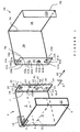
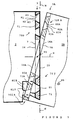
- the figure 1 represents, in perspective front and left side, a first sheet 9, here sheet metal, intended to be coupled to a second sheet 9A of the same shape, as illustrated by the figure 2 .
- the description of the constitution of the elements relates essentially to the first sheet 9 and if necessary on the second sheet 9A.
- Each element of the second sheet 9A bears the same reference as the identical element of the first sheet 9, with the addition of the suffix A, so that the explanation given for one of them of such a pair of twins is to transpose for the other.
- the first and second sheets 9 and 9A are supposed to be oriented according to their final position of assembly of the cabinet, that is to say extending in vertical planes. Of course, the explanations below would remain valid, with the desired transposition, if the first and second sheets 9 and 9A were oriented otherwise.
- the first panel 1 is limited, opposite the vertical rear side fold 6, by a vertical front side fold 5 which separates it from a relatively narrow front flap 10, a vertical free edge defines a door opening.
- the second panel 2 comprises, opposite the rear lateral fold 6, a vertically extending coupling edge strip 3 comprising hermaphrodite coupling elements with the same coupling edge strip 3A of the second sheet 9A, connected by a rear fold 7A, a second panel 2A itself connected by a rear side fold 6A to a first panel 1A, separated from a front panel 10A by a front fold 5A.
- the coupling edge strip 3 is a flap folded at 90 degrees forward, that is to say parallel to the first panel 1, around a vertical rear fold 7, opposite to a vertical free edge 39.
- the coupling edge strip 3 has an internal lateral face 14 opposite to an external lateral face 15, coupling, in a vertical median plane M of the cabinet, by pressing on a lateral external side homologue 15A of the coupling edge band 3A, itself opposite to an internal lateral face 14A.
- the arrow F0 serves to locate the horizontal direction forward in the various figures.
- the sheet 9A has the same lights, not drawn for the sake of clarity. In a dual manner, the lights 12 can be replaced by support tabs folded horizontally.
- the shelf 11 is here provided to extend over the entire width of the cabinet, that is to say that it comprises a rear notch accommodating the coupling edge strips 3 and 3A, which may also be provided with lights 12.
- a cap 18, of which only a corner portion is shown, is provided for gripping the top slices of the sheets 9 and 9A.
- the hermaphrodite coupling edge band 3 is provided with a plurality of at least one pair of complementary coupling protrusions, male and female respectively, located at positions which are generally symmetrical relative to a plane horizontal symmetry S located substantially mid-length of the coupling strip 3, to thereby allow to build a frame or cabinet trim by coupling head to tail of a pair of such sheets 9 and 9A, on the one hand and other of the median vertical plane M of the cabinet.
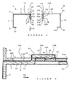
- the male reliefs 20, consisting of elements 21-25, 40-42, and the female reliefs 30, constituted by elements 31-33, 50-52, are explained in relation to the following figures.
- the male reliefs 20, clearly visible on the Figures 2 and 3 here consist essentially of a tongue 21 elastically deformable and having an angled side edge profile, with a foot 22 of lateral offset of a coupling lug 23 on the other side of the median plane M.
- the female reliefs 30 here comprise a passage cutout 31, of the same size as the tongue 21, to allow the passage of the tongue 21A of the second sheet 9A, belonging to the male reliefs 20A.
- the tongue 21 is here located in an upper end portion of the coupling edge strip 3 and the cutout 31 is located opposite in a lower end section.
- the tongue 21 and the cutout 31 are thus located in two respective positions having specular symmetry with respect to the horizontal plane of symmetry S.
- the plane of symmetry S thus intersects the coupling edge band 3 in a horizontal line at mid-height 90 which contains a point of rotation 91 for the coupling of the two coupling edge strips 3 and 3A, as explained later.
- the coupling lug 23 extends generally in a vertical plane parallel to the median plane M, and therefore also to an overall extension plane of the coupling edge band 3, and extends functionally in a horizontal direction, here to 'before.
- the lateral offset length of the foot 22 corresponds to a thickness value of the coupling edge band 3A (and thus also of the coupling edge band 3), so that the coupling lug 23 constitutes a clamping jaw which passes through a passage cutout 31A limited forward by a locking portion 32A of the coupling edge strip 3A.
- the coupling lug 23 delimits, with the external lateral surface 15, a housing 28 ( Fig. 3 ) of thickness adjusted to receive the locking section 32A. Specifically, the zone comprising the rigid locking section 32A will be clamped between the coupling lug 23 and a periphery zone before, on the outer lateral surface 15, of a cut zone the material of which has served to form the tongue. 21.
- male and female essentially have a simple purpose of clarity in order to differentiate the two coupling elements, but that, for example, the so-called male element 22, 23 could equally well be called female, since it defines the housing 28 in which the locking section 32A penetrates, which could therefore be considered as male.
- the holding in final coupling position could be ensured by a simple elastic support of the tab 23 on the locking section 32A, the tab 23 then having to be shaped slightly folded to occupy at rest a position such that the housing 28 has a throat thickness, preferably with an input bevel at the end of the lug 23 or the coupling edge strip portion 3A, so that the latter arms the clamping spring that constitutes the leg 23.
- the tab 23 carries a male element forming a non-return catch 24 intended to penetrate into a locking hole 33A (see also Fig. 1 ) arranged at the front of the locking section 32A.
- the pawl 24 forms a side hook inside the housing 28, with a ramp before the locking section 32A will push laterally to open the housing 28 to the desired thickness, and with a rear end surface 25 , which, once the pawl 24 expanded by its complete frame with the locking slot 33A, will be opposite an anterior surface 34A of the locking light 33A.
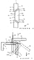
- the figure 4 is a side view of the coupling edge strip 3 and behind the coupling edge strip 3A. Because the tilting of the second sheet 9A is lateral, the tabs 23 and 23A are both oriented in the same way, horizontally forward, and the locking slots 33 and 33A occupy the desired position in front of them. this. It will be noted that the precise position of the cut 31A, that is to say its distance to the free edge 39A of the coupling edge band 3A, thus corresponds to a frame with the lug 23 in the initial position, initiating coupling movement with locking, this frame thus disappearing in the final position of effective coupling, since the Coupling rotation is intended to establish a locking by deleting the framing.
- the operator initially slightly tilts the top of the second sheet 9A in the median plane M around the point of rotation 91 towards the front of the cabinet, and therefore with it the coupling edge band 3A as shown on the figure 4 , whose direction of extension, initially vertical according to the figure 1 , has tilted slightly in the direction of clockwise.
- the passage cutouts 31 and 31A allow, in this initial position, the passage in lateral offset of the tabs 23A and 23 to initiate the coupling, so that the outer lateral surfaces 15 and 15A bear against each other in the median plane M.
- the coupling at the upper end is effected by the fact that the female element of the second sheet 9A (locking hole 33A ) is coupled to the male element of the first sheet 9 (pawl 24) in the housing 28, while at the lower end, it is the male element (tab 23A) of the second sheet 9A which is coupled to the locking aperture 33 of the first sheet 9, a rear end surface 25A of a pawl 24A locking.
- the male and female reliefs 30 further comprise respectively a pin 40 and a corresponding light 50, centering the second sheet 9A by coupling with respectively the same light 50A and the same pin 40A, so that the pins 40, 40A are guided so as to provide a hub function around the point of central rotation 91, relative pivoting between the two coupling edge strips 3, 3A.
- the lug 23, 23A of any one of the two sheets 9, 9A and the corresponding passage cutout 33A, 33 of the other sheet 9A 9, it is thus defined the position of an arc of sweeping around the central point of rotation 91, bringing them into the coupling position, as explained in connection with the figure 4 .
- the respective nipple 40, 40A presents here ( Fig. 2 ) a mushroom profile, with a neck section 41, 41A carrying a head 42, 42A arranged to couple ( Fig. 4 ) to the lumen 50A, 50 of the other sheet 9A, 9 crossing, from the outer lateral surface 15A, 15 to the inner lateral face 14A, 14, of an enlarged inlet end 51A, 51 of the 50A, 50.
- the head 42, 42A is dimensioned in width to remain trapped, on the side of the internal lateral face 14A, 14 of the opposed light 50A, 50, when the neck section 41, 41A slides in a section 52A, 52 constituting a guide rail for locking by slight rotation according to the figure 4 .
- the two pins 40, 40A thus define, at mid-distance mutual, the position in height of the central point of rotation 91, with respect to which they are thus substantially diametrically opposed. Given the low locking rotation, the guide sections 52, 52A can be almost rectilinear.
- the pin 40 is not necessarily in alignment with the tongue 21 with the notch passage 31, as also suggests the figure 4 .
- the positions of the two pins 40, 40A substantially define a diameter, it may well be provided an angularly rotated arrangement, for example a quarter of a turn, compared to that drawn, with the pin 40 ( 40A) and the guide light 50 (50A) both generally in the horizontal plane of symmetry S.
- such a mounting further ensures a complementary coupling to keep the external lateral surfaces 15 and 15A mutually clamped.
- the lug 23 has a free end twisted to project, by a first free end wedge, out of the internal "lateral" face 14 and, by a second free end wedge, out of the outer "lateral” surface 15.
- the locking section 32A then has no free rectilinear edge, that is to say vertical, but is serrated by a relief serving as a rostrum for engage the first under the free end corner of the tab 23 which is raised, to raise it sufficiently so that the rest of the coupling edge strip portion 3A, with the lock slot 33A, can access the Inside the housing 28.
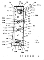
- FIGS 5 to 7 illustrate the second embodiment of a sheet according to the invention, which differs from the first embodiment only in the embodiment of the coupling edge strip 3, 3A.
- the general structure follows that of the figure 1 , with also the possibility of the variant according to which the coupling edge strip 3 is coplanar with the second panel 2. For the sake of brevity, it will therefore be exposed only the differences with respect to the first embodiment.
- the coupling reliefs here consist of an upper half-serration 70S and a lower half-serration 70I together forming a serration 70 with teeth 71, having an upper edge 72 and two sidewalls 73, 75, alternating with indentations 81 with bottom 82 and with side edges 83, 85. Because of the alternation of the teeth 71 and notches 81, the two references 73, 83 (and also 75, 85) designate the same sidewall surface. This duplication has a purpose of clarity, since it makes it possible subsequently to use one or other of these references depending on whether a tooth 71 or a notch 81 is respectively mentioned.
- flanks 73, 75, or side edges 83, 85 are oriented bevel, and, precisely, somewhat turned towards the internal lateral face 14, so are visible on the figure 5 .
- this orientation can be returned, towards the outer face 15, for the whole of the serration 70 or for one of the halves (upper half 70S on the figure 7 where the mouth of the upper indentations 81 is on the side of the outer lateral surface 15).
- each tooth 71 and the notch 81 in a symmetrical position relative to the central point of rotation 91 are a pair of elements of the same lateral profile, this profile can however change from one pair to another.
- the male, tooth 71, and female, notch 81, members of the same pair are thus of the same shape to be able to interlock the coupling edge strips 3 and 3A mutually in the manner of a puzzle, that is to say in a common plane, the top edges 72A of the teeth 71A of the coupling edge strip 3A thus facing the bottom 82 of the indentations 81.
- the notches 81 thus having a dovetail side profile, thus with a bottleneck opposite the bottom 82, the teeth 71 having the same side profile, the top edge 72 having an extension greater than the bottleneck .
- the serrations 70, 70A and notches 80, 80A of the two sheets 9 and 9A can, as desired, be coupled by edge-to-edge, in the plane of the figure 5 , the edges of the coupling edge strips 3 and 3A and bringing them together to nest them, or by superimposing them according to the desired framing and then pressing them against each other, perpendicular to the plane of the figure 5 .
- the latter solution is here the only one possible, that is to say that the penetration of a tooth 71 into a notch 81A is effected laterally, in the direction of the thickness.
- the two lateral edges 83 and 85 of the notch 81 have an extension direction inclined with respect to a normal to the internal lateral faces 14 and external 15, that is to say that notch 81 has a passage template which narrows from the outer lateral face 15, where the mouth of receiving the tooth 71A is, towards the inner lateral face 14.
- each side edge 83, 85 has, at mid-thickness, an abrupt narrowing of the passage template, in the form of a respective shoulder 84, 86 which is therefore turned towards the external lateral face 15. It will have been understood that, in such a case, the rest of the lateral edge 83, 85 could be, contrary to the drawing, perpendicular to the outer side face 15, since the shoulder 84, 86 ensures the desired overall shrinkage.
- the tooth 71A, flanks 73A and 75A having respective shoulders 74A and 76A, and, on the other hand, the notch 81 have two same lateral profiles, that is to say the same shape and same size, which vary in the same way according to the position in thickness, it is conceivable that the tooth 71A, with such shoulders 74A and 76A, fits exactly in the volume defined by the notch 81, the narrowing preventing it from emerging at the level of the internal lateral face 14. It is therefore a three-dimensional positioning.
- the direction of the constriction of the passage template is reversed between the upper half-serration 70S, located above the horizontal plane of symmetry S, and the lower half-serration 70I.
- first case which relates to the above variant free of back fold 7, that is to say for which the coupling edge strips 3 and 3A are coplanar with the second panel 2, respectively 2A.
- a second case will then be exposed, concerning the "basic" form, that is to say with the rear fold 7.
- the two coupling edge strips 3, 3A are first brought into contact, according to the figure 7 , by their edge in the half-height zone comprising the plane of symmetry S.
- the half-serrations 70S and 70I are mutually disjointed, being separated by a vertical rectilinear section 70M ( figure 5 ), therefore free of teeth in this central area, that is to say, representing the bottom a central notch 81C, relatively wide in vertical extension, of depth equal to half the height / depth of the teeth 71 / notches 81.
- the corrugation of the serration 70, on either side of a vertical line average (section 70M), is then zero.
- the two half-serrations 70S, 70I of the coupling edge band 3 must therefore have a point symmetry with respect to the point of rotation 91, located on the section 70M or in other words, to have a mirror symmetry with respect to the horizontal plane of symmetry S, with however a relative vertical offset of a half-step of serration so that a tooth 71, becoming a tooth 71A for the second sheet 9A, finds himself facing a notch 81.
- this final coupling rotation is carried out according to the principle of rotation of the figure 4 , the teeth 71A being the equivalent of the legs 23A and penetrating into the corresponding notch 81, by a rotation, around the horizontal line at mid-height 90 ( figure 5 ) in the opposite direction of clockwise in the case of drawing of the figure 6 .
- the lateral edges 83A, 85A are applied on the flanks 83, 85 opposite.
- the penetration is carried out first by their external lateral surface area 15A which is forward, with respect to the direction of movement parallel to the plane of the panel 2, while for the teeth 71A of the lower half, it will be their inner side face area 14A which will be forward.
- the coupling edge strips 3 and 3A are locked in offset. thickness in both directions by the respective ends opposite half-serrations 70S and 70I, close to each other on either side of the horizontal plane of symmetry S.
- a complementary blocking element in rotation at the top and / or at the bottom, for example a local clamp of the corresponding end of the coupling edge strips 3 and 3A or, generally, the cap 18 enclosing the whole of the upper end of the sheets 9 and 9A and a base of the same type, or rivets.
- the cap 8 is here U-shaped returned, to form a clamp all around the upper perimeter of the cabinet, thus inhibiting any decoupling movement between the coupling edge strips 3 and 3A.
- the indentations 81 of the lower half serration 701 are deepened, that is to say project slightly beyond the rear fold 7, in the second panel 2, by a notch extension 81E limited by a remote bottom 81D replacing the bottom 82.
- the second panel 2 thus forms, with the coupling edge band 3, a kind of rake hand, a basic phalanx is in the plane of the palm (section of the panel 2 to horizontal extension on the figure 8 ) and whose other knuckles are folded forward at the rear fold 7.
- the upper edge 72A of the teeth 71A of the same rake constituted by the coupling edge strip 3A, of the same shape, can thus be presented to the rear of the first phalanges above, that is to say, at the remote bottom 81D deep indentations 81, then advance the second panel 2A to the plane of the second panel 2 according to the arrow F2. Two possibilities can be foreseen in this phase.
- the coupling edge band 3A is vertical and therefore parallel to the coupling edge band 3 and facing the internal lateral face 14, so that the final coupling movement will be a lateral translation, according to the arrow F3, bypassing the coupling edge band 3A from the rear side fold 6, to bring the coupling edge band 3A back into the median plane M, defined by the coupling edge band 3.
- the teeth 71A and indentations 81A are thus interlocking respectively with the notches 81 and the teeth 71, in front of which they were previously framed by the advance movement above.
- the coupling edge strip 3A is initially presented in a slightly inclined orientation on the vertical, according to the figure 7 , with crossing with the coupling edge band 3 at the level of the horizontal line at half height 90, according to the principle explained for the figure 4 . It is therefore only the lower half-serration 70IA which penetrates into the notch extensions 81E, while the upper half-serration 70SA is beyond the median plane M, that is to say on the side of the external lateral face 15. The rotation, in its plane, of the second panel 2A with the coupling edge band 3A brings it back to the median plane M, thus coupling with the coupling edge band 3.
- the profiles, in transverse section, of the teeth 71 , 71A and notches 81, 81A and bottom 82A, are then in the form of trapezoid.
- the indentations 81 of the lower half serration 70I have a clearance gauge which decreases from the internal lateral face 14, mouth, which "sees" arriving teeth 71A of the lower half serration 70IA, towards the lateral face external 15, while the indentations 81 of the upper half-serration 70S have a clearance template which decreases from the external lateral face 15, which "sees” arrive the teeth 71A of the upper half-serration 70SA, towards the internal lateral face 14.
- the Figures 9 to 13 represent a variant of the teeth 71 and notches 81 bevel.
- the essential difference from the embodiment according to the figure 7 where there is inversion of the direction of the bevel between the upper half-serration 70S and the lower half-serration 70I, lies in the fact that all the teeth 71 have at least one sidewall having two respective beveled sections having sign angles opposite ( Figures 11-12 ).
- the teeth are all of the same type, from this point of view.
- This embodiment allows a buttoning of the coupling edge strips 3 and 3A in the same plane. The rear fold 7 is therefore useless.
- the figure 9 represents an area of the internal "lateral" face 14, which is in fact turned towards the front.
- the coupling edge strip 3 has a notch 81 which is functionally divided into two angled portions with opposite sign angles. Indeed, at the mouth near the free edge 39, the notch 81 includes an outer section 81X, or mouthpiece, whose side edges 83, 85 have a bevel 830, respectively 850, turned somewhat towards the inner side face 14 , whereas, on the side of the bottom 82 of the notch 81, the lateral edges 83, 85 and the bottom 82 have an inner section 831, or bottom, having a bevel 835, respectively 855, somewhat turned towards the lateral face external 15, hidden here. In general, and as already mentioned, it suffices, in principle, at least one beveled surface in each direction, that is to say that the bevel of the bottom 82 and one of the side edges 83, 85 is a redundant element.
- the outer portion, 83X, of the lateral edge 83 thus has the bevel surface 830 intersecting the inner lateral faces 14 and outer 15 along two respective lines 831 and 834, see also figure 11 .
- Line 831 thus represents a lateral mouth having a maximum of the transverse passage gauge, perpendicular to the plane of the figure 9 , that is to say in thickness, offered to the tooth 71 from the internal lateral face 14 to the external lateral face 15, and the line 834 corresponds to a minimum of this passage template at the external lateral face 15 .
- the facing external section, 85X, belonging to the lateral edge 85 similarly has the bevel 850 turned somewhat towards the internal lateral face 14, with lines 851, 852, 853, 854 homologous to the lines 831, 832, 833, 834.
- the internal sections 83I and 85I of the lateral edges 83 and 85 likewise here the bottom 82, have a bevel which, meanwhile, is turned somewhat towards the external lateral face 15, thus hidden on the figure 9 .
- the inner portion 83I of the lateral edge 83 thus has the bevel surface 835 intersecting the inner and outer lateral faces 14 and 14 along respective lines 839 and 836, see also figure 12 .
- the line 836 thus represents a lateral mouth having a maximum of the transverse passage gauge, that is to say in thickness, offered to the tooth 71 from the external lateral face 15 to the internal lateral face 14, and the line 839 corresponds to a minimum of this passage template at the internal lateral face 14. It has likewise been drawn two intermediate lines 837 and 838 from the line 836 to the line 839.
- the facing inner portion 85I belonging to the side edge 85 likewise has the bevel 855 turned somewhat towards the outer side face 15 with lines 856, 857, 858, 859 homologous lines 836, 837, 838, 839. It is the same for the bottom 82, with a bevel surface 825 and respective lines 826, 827, 828, 829.
- the two sections 831, 83X, respectively 851, 85X, of each lateral edge 83, 85 are separated by a cutout 830D, respectively 850D, whose distance between the two bottom corresponds to the width of the tooth 71, that is to say the vertical dimension of the latter on the figure 10 .
- the dotted line rectangle referenced 71A thus represents the position of presentation of the tooth 71A to initiate the coupling.
- a tooth 71 after reversal in the plane of Figures 9 and 10 i.e., it occupies the position of a tooth 71A of the sheet 9A.
- the tooth 71 as returned to the figure 10 , represents, in male form, the housing space delimited by the various bevels of the notch 81.
- the figure 10 represents another zone of the internal "lateral" face 14.
- the coupling edge strip 3 comprises the tooth 71 which is functionally divided into two sections, internal and external, with bevels at opposite angles of angles. Indeed, near its base, at a distance from the free edge 39, the tooth 71 comprises an inner section 71I whose sides 73, 75 have a respective bevel 730, 750 turned somewhat towards the external lateral face 15, see figure 11 whereas, on the side of the apex 72, the flanks 73, 75 and the apex 72 have an outer section 71X having a bevel 735, 755, 725 somewhat turned towards the internal lateral face 14, see also figure 12 .
- the inner section, 73I, of the sidewall 73 thus has the bevel surface 730 intersecting the inner and outer lateral faces 14 and along two respective lines 731 and 734.
- the line 734 thus corresponds, upwards, to a minimum of the jig. transverse occupation, that is to say in thickness, of the tooth 71, at the level of the external lateral face 15, and the line 734 corresponds to a maximum of this occupation mask at the internal lateral face 14.
- the facing internal section 75I belonging to the sidewall 75 likewise presents the bevel 750 turned somewhat towards the external lateral face 15, with lines 751, 752, 753, 754 homologous to the lines 731, 732, 733, 734.
- the outer portion 73X of the sidewall 73 thus has the bevel surface 735 intersecting the inner and outer lateral faces 14 and along two respective lines 739 and 736, see also figure 12 .
- Line 736 thus represents a maximum of the transverse occupation gauge, that is to say in thickness, of tooth 71, and line 739 corresponds to a minimum of this occupation mask at the level of the internal lateral face. 14.
- two intermediate lines 737 and 738 were drawn, staggered from line 736 to line 739.
- the opposite external section, 75X, belonging to the flank 75 likewise presents the bevel 755 turned somewhat towards the internal lateral face 14, with lines 756, 757, 758, 759 homologous to the lines 736, 737, 738, 739. It the same is true for the apex 72, with respective lines 726 (maximum occupancy mask), 727, 728, and 729 (minimum occupancy mask).
- the two sections 73I, 73X, respectively 75I, 75X, of each side 73, 75 are separated by an intermediate section 730D, respectively 750D, which can be, as here, free of bevel.
- the figure 13 represents the tooth 71 in plan view, that is to say the opposite top bevels.
- the two hatched areas correspond to the respective lower parts of the two upper bevel surfaces, internal 730 and external 735, that is to say their zone near the external lateral face (line 734), respectively internal 14 (line 739). .
- the two coupling edge strips 3 and 3A are mutually arranged vertically at right angles, so that the tooth 71 of the figure 10 (Actually the tooth 71A) is presented frontally facing the intermediate portion of the notch 81, that is to say for the respective outer sections 73X, 75X flanks 73, 75 through the cuts 830D, 850D.
- the tooth 71 With the tooth 71 thus half engaged, it is then rotated, with the rest of the coupling edge band 3A, about a vertical axis 100 centered on the cutouts 830D, 850D, to fold the outer bevel surfaces 735 , 755 and 725 of its outer sections 73X, 75X and 72 against the inner portion 81I having the bevelled inner surfaces 835, 855 and 825. Symmetrically with respect to the axis 100, the inner bevel surfaces 730, 750 of the internal sections 73I, 75I of the tooth 71 (actually 71A) are folded against the outer section 81X having the bevelled surfaces 830, 850.
- the lateral profile of the notch 81 and the tooth 71 according to the Figures 9 and 10 may not be rectangular as drawn.
- the outer section 83X of the mouthpiece 81 and the corresponding inner section 71I of the tooth 71 may have a dovetail profile. i.e. the outer sections 83X and 85X diverge mutually away from the free edge 39.
- the cabinet can thus be of great width while being free of internal relief coupling between the sheets 9 and 9A.
Landscapes
- Engineering & Computer Science (AREA)
- General Engineering & Computer Science (AREA)
- Mechanical Engineering (AREA)
- Connection Of Plates (AREA)
Priority Applications (1)
| Application Number | Priority Date | Filing Date | Title |
|---|---|---|---|
| PL07291087T PL1900303T3 (pl) | 2006-09-13 | 2007-09-11 | Płyta materiału konstrukcyjnego |
Applications Claiming Priority (1)
| Application Number | Priority Date | Filing Date | Title |
|---|---|---|---|
| FR0607986A FR2905574B1 (fr) | 2006-09-13 | 2006-09-13 | Feuille de materiau de construction. |
Publications (2)
| Publication Number | Publication Date |
|---|---|
| EP1900303A1 EP1900303A1 (fr) | 2008-03-19 |
| EP1900303B1 true EP1900303B1 (fr) | 2012-05-30 |
Family
ID=37831612
Family Applications (1)
| Application Number | Title | Priority Date | Filing Date |
|---|---|---|---|
| EP07291087A Active EP1900303B1 (fr) | 2006-09-13 | 2007-09-11 | Feuille de matériau de construction |
Country Status (4)
| Country | Link |
|---|---|
| EP (1) | EP1900303B1 (pl) |
| ES (1) | ES2390483T3 (pl) |
| FR (1) | FR2905574B1 (pl) |
| PL (1) | PL1900303T3 (pl) |
Families Citing this family (3)
| Publication number | Priority date | Publication date | Assignee | Title |
|---|---|---|---|---|
| US20090140616A1 (en) * | 2007-12-04 | 2009-06-04 | Anthony Fox | Trash compactor cabinet |
| CN102940399A (zh) * | 2012-11-22 | 2013-02-27 | 冯中宇 | 一种不锈钢橱柜可拆装式柜体及子母扣件 |
| FR3005553B1 (fr) * | 2013-05-16 | 2015-05-15 | Yves Daniel Niddam | Bacs et jardinieres interieurs et exterieurs en metal, a montage et demontage sans outils |
Family Cites Families (4)
| Publication number | Priority date | Publication date | Assignee | Title |
|---|---|---|---|---|
| US4077686A (en) * | 1977-01-10 | 1978-03-07 | Kero Metal Products Co., Inc. | Prefabricated metal storage cabinets |
| AT409071B (de) * | 1997-11-24 | 2002-05-27 | Alfit Ag | Schubkasten |
| NL1025719C2 (nl) * | 2004-03-13 | 2005-09-14 | Vika Metaal B V | Samenstel van mechanisch koppelbare plaatdelen. |
| JP4530780B2 (ja) * | 2004-09-28 | 2010-08-25 | 株式会社アールテック・リジョウ | 鋼板製の組立ブロック箱枠棚用の枠板と該枠板から組立ブロック箱枠及び組立ブロック箱枠棚 |
-
2006
- 2006-09-13 FR FR0607986A patent/FR2905574B1/fr active Active
-
2007
- 2007-09-11 EP EP07291087A patent/EP1900303B1/fr active Active
- 2007-09-11 PL PL07291087T patent/PL1900303T3/pl unknown
- 2007-09-11 ES ES07291087T patent/ES2390483T3/es active Active
Also Published As
| Publication number | Publication date |
|---|---|
| ES2390483T3 (es) | 2012-11-13 |
| FR2905574B1 (fr) | 2008-11-14 |
| EP1900303A1 (fr) | 2008-03-19 |
| FR2905574A1 (fr) | 2008-03-14 |
| PL1900303T3 (pl) | 2012-11-30 |
Similar Documents
| Publication | Publication Date | Title |
|---|---|---|
| EP2641505B1 (fr) | Caisson de meuble | |
| FR2476329A1 (fr) | Boitier pour vues de meme format | |
| EP0900037A1 (fr) | Siege compose d'elements assemblables | |
| EP0216669A1 (fr) | Système d'assemblage d'éléments en plaques, en une matière semi-rigide et application au verrouillage en position montée de croisillons pour casiers à bouteilles | |
| EP1900303B1 (fr) | Feuille de matériau de construction | |
| EP0657595A1 (fr) | Système de cloisonnement à poteaux flottants | |
| FR2956590A1 (fr) | Jeu de construction | |
| FR2955837A1 (fr) | Plateau de transport et de presentation d'articles, tels que des pots de yaourt, de rigidite amelioree | |
| WO1995027834A1 (fr) | Procede et dispositif d'assemblage de profiles, et structure demontable en faisant application | |
| FR2741459A1 (fr) | Charniere elastique de lunettes a coulisse | |
| EP0017574B1 (fr) | Noeud d'assemblage pour structure spatiale, et structure spatiale équipée d'un tel noeud | |
| EP3443864A1 (fr) | Charniere, dispositif articule forme par ou comportant au moins une telle charniere et procede de fabrication de ladite charniere | |
| WO2014096577A1 (fr) | Caisson de meuble | |
| FR2727354A1 (fr) | Presentoir de documents | |
| EP0268542B1 (fr) | Système d'assemblage montable, démontable et autobloquant d'élément de structure | |
| FR2693984A1 (fr) | Bac de rangement démontable. | |
| FR2964130A1 (fr) | Systeme de maintien en position d'un coffrage de pilier, ensemble de coffrage et procede de coulage d'un pilier | |
| WO2012010756A1 (fr) | « plateau de transport et de présentation d'articles, tels que des pots de yaourt, de rigidité améliorée » | |
| EP1035789A1 (fr) | Meuble compose d'elements assemblables | |
| EP0121487B1 (fr) | Rayonnage à étagères bloquables par coincement | |
| EP0908126B1 (fr) | Ensemble comprenant une échelle et un chevalet pour le support d'articles | |
| EP1544404B1 (fr) | Grille à barreaux amovibles verrouillés | |
| WO2018115754A1 (fr) | Tablette métallique configurée pour équiper un dispositif de présentation d'articles de marchandise, telle qu'une gondole | |
| FR3060284A1 (fr) | Tablette metallique configuree pour equiper un dispositif de presentation d'articles de marchandise, notamment une gondole | |
| FR2502709A3 (fr) | Perfectionnements apportes aux systemes d'attache et aux ensembles comportant de tels systemes d'attache |
Legal Events
| Date | Code | Title | Description |
|---|---|---|---|
| PUAI | Public reference made under article 153(3) epc to a published international application that has entered the european phase |
Free format text: ORIGINAL CODE: 0009012 |
|
| AK | Designated contracting states |
Kind code of ref document: A1 Designated state(s): AT BE BG CH CY CZ DE DK EE ES FI FR GB GR HU IE IS IT LI LT LU LV MC MT NL PL PT RO SE SI SK TR |
|
| AX | Request for extension of the european patent |
Extension state: AL BA HR MK YU |
|
| 17P | Request for examination filed |
Effective date: 20080919 |
|
| AKX | Designation fees paid |
Designated state(s): AT BE BG CH CY CZ DE DK EE ES FI FR GB GR HU IE IS IT LI LT LU LV MC MT NL PL PT RO SE SI SK TR |
|
| GRAP | Despatch of communication of intention to grant a patent |
Free format text: ORIGINAL CODE: EPIDOSNIGR1 |
|
| RIN1 | Information on inventor provided before grant (corrected) |
Inventor name: GAREST, SEBASTIEN Inventor name: DECEUVELAERE, FREDERIC Inventor name: DECAYEUX, ETIENNE |
|
| GRAS | Grant fee paid |
Free format text: ORIGINAL CODE: EPIDOSNIGR3 |
|
| GRAA | (expected) grant |
Free format text: ORIGINAL CODE: 0009210 |
|
| AK | Designated contracting states |
Kind code of ref document: B1 Designated state(s): AT BE BG CH CY CZ DE DK EE ES FI FR GB GR HU IE IS IT LI LT LU LV MC MT NL PL PT RO SE SI SK TR |
|
| REG | Reference to a national code |
Ref country code: GB Ref legal event code: FG4D Free format text: NOT ENGLISH |
|
| REG | Reference to a national code |
Ref country code: CH Ref legal event code: EP |
|
| REG | Reference to a national code |
Ref country code: AT Ref legal event code: REF Ref document number: 559642 Country of ref document: AT Kind code of ref document: T Effective date: 20120615 |
|
| REG | Reference to a national code |
Ref country code: IE Ref legal event code: FG4D Free format text: LANGUAGE OF EP DOCUMENT: FRENCH |
|
| REG | Reference to a national code |
Ref country code: DE Ref legal event code: R096 Ref document number: 602007022963 Country of ref document: DE Effective date: 20120726 |
|
| REG | Reference to a national code |
Ref country code: RO Ref legal event code: EPE |
|
| REG | Reference to a national code |
Ref country code: NL Ref legal event code: VDEP Effective date: 20120530 |
|
| REG | Reference to a national code |
Ref country code: LT Ref legal event code: MG4D Effective date: 20120530 |
|
| PG25 | Lapsed in a contracting state [announced via postgrant information from national office to epo] |
Ref country code: IS Free format text: LAPSE BECAUSE OF FAILURE TO SUBMIT A TRANSLATION OF THE DESCRIPTION OR TO PAY THE FEE WITHIN THE PRESCRIBED TIME-LIMIT Effective date: 20120930 Ref country code: SE Free format text: LAPSE BECAUSE OF FAILURE TO SUBMIT A TRANSLATION OF THE DESCRIPTION OR TO PAY THE FEE WITHIN THE PRESCRIBED TIME-LIMIT Effective date: 20120530 Ref country code: FI Free format text: LAPSE BECAUSE OF FAILURE TO SUBMIT A TRANSLATION OF THE DESCRIPTION OR TO PAY THE FEE WITHIN THE PRESCRIBED TIME-LIMIT Effective date: 20120530 Ref country code: CY Free format text: LAPSE BECAUSE OF FAILURE TO SUBMIT A TRANSLATION OF THE DESCRIPTION OR TO PAY THE FEE WITHIN THE PRESCRIBED TIME-LIMIT Effective date: 20120530 Ref country code: LT Free format text: LAPSE BECAUSE OF FAILURE TO SUBMIT A TRANSLATION OF THE DESCRIPTION OR TO PAY THE FEE WITHIN THE PRESCRIBED TIME-LIMIT Effective date: 20120530 |
|
| REG | Reference to a national code |
Ref country code: ES Ref legal event code: FG2A Ref document number: 2390483 Country of ref document: ES Kind code of ref document: T3 Effective date: 20121113 |
|
| REG | Reference to a national code |
Ref country code: AT Ref legal event code: MK05 Ref document number: 559642 Country of ref document: AT Kind code of ref document: T Effective date: 20120530 |
|
| PG25 | Lapsed in a contracting state [announced via postgrant information from national office to epo] |
Ref country code: GR Free format text: LAPSE BECAUSE OF FAILURE TO SUBMIT A TRANSLATION OF THE DESCRIPTION OR TO PAY THE FEE WITHIN THE PRESCRIBED TIME-LIMIT Effective date: 20120831 Ref country code: LV Free format text: LAPSE BECAUSE OF FAILURE TO SUBMIT A TRANSLATION OF THE DESCRIPTION OR TO PAY THE FEE WITHIN THE PRESCRIBED TIME-LIMIT Effective date: 20120530 Ref country code: SI Free format text: LAPSE BECAUSE OF FAILURE TO SUBMIT A TRANSLATION OF THE DESCRIPTION OR TO PAY THE FEE WITHIN THE PRESCRIBED TIME-LIMIT Effective date: 20120530 |
|
| REG | Reference to a national code |
Ref country code: PL Ref legal event code: T3 |
|
| PG25 | Lapsed in a contracting state [announced via postgrant information from national office to epo] |
Ref country code: AT Free format text: LAPSE BECAUSE OF FAILURE TO SUBMIT A TRANSLATION OF THE DESCRIPTION OR TO PAY THE FEE WITHIN THE PRESCRIBED TIME-LIMIT Effective date: 20120530 Ref country code: NL Free format text: LAPSE BECAUSE OF FAILURE TO SUBMIT A TRANSLATION OF THE DESCRIPTION OR TO PAY THE FEE WITHIN THE PRESCRIBED TIME-LIMIT Effective date: 20120530 Ref country code: CZ Free format text: LAPSE BECAUSE OF FAILURE TO SUBMIT A TRANSLATION OF THE DESCRIPTION OR TO PAY THE FEE WITHIN THE PRESCRIBED TIME-LIMIT Effective date: 20120530 Ref country code: SK Free format text: LAPSE BECAUSE OF FAILURE TO SUBMIT A TRANSLATION OF THE DESCRIPTION OR TO PAY THE FEE WITHIN THE PRESCRIBED TIME-LIMIT Effective date: 20120530 Ref country code: DK Free format text: LAPSE BECAUSE OF FAILURE TO SUBMIT A TRANSLATION OF THE DESCRIPTION OR TO PAY THE FEE WITHIN THE PRESCRIBED TIME-LIMIT Effective date: 20120530 Ref country code: EE Free format text: LAPSE BECAUSE OF FAILURE TO SUBMIT A TRANSLATION OF THE DESCRIPTION OR TO PAY THE FEE WITHIN THE PRESCRIBED TIME-LIMIT Effective date: 20120530 |
|
| PG25 | Lapsed in a contracting state [announced via postgrant information from national office to epo] |
Ref country code: PT Free format text: LAPSE BECAUSE OF FAILURE TO SUBMIT A TRANSLATION OF THE DESCRIPTION OR TO PAY THE FEE WITHIN THE PRESCRIBED TIME-LIMIT Effective date: 20121001 |
|
| BERE | Be: lapsed |
Owner name: ETABLISSEMENTS DECAYEUX SOC. PAR ACTIONS SIMPLIFI Effective date: 20120930 |
|
| PLBE | No opposition filed within time limit |
Free format text: ORIGINAL CODE: 0009261 |
|
| STAA | Information on the status of an ep patent application or granted ep patent |
Free format text: STATUS: NO OPPOSITION FILED WITHIN TIME LIMIT |
|
| PG25 | Lapsed in a contracting state [announced via postgrant information from national office to epo] |
Ref country code: MC Free format text: LAPSE BECAUSE OF NON-PAYMENT OF DUE FEES Effective date: 20120930 |
|
| REG | Reference to a national code |
Ref country code: CH Ref legal event code: PL |
|
| 26N | No opposition filed |
Effective date: 20130301 |
|
| REG | Reference to a national code |
Ref country code: IE Ref legal event code: MM4A |
|
| REG | Reference to a national code |
Ref country code: DE Ref legal event code: R097 Ref document number: 602007022963 Country of ref document: DE Effective date: 20130301 |
|
| PG25 | Lapsed in a contracting state [announced via postgrant information from national office to epo] |
Ref country code: BE Free format text: LAPSE BECAUSE OF NON-PAYMENT OF DUE FEES Effective date: 20120930 Ref country code: IE Free format text: LAPSE BECAUSE OF NON-PAYMENT OF DUE FEES Effective date: 20120911 Ref country code: LI Free format text: LAPSE BECAUSE OF NON-PAYMENT OF DUE FEES Effective date: 20120930 Ref country code: BG Free format text: LAPSE BECAUSE OF FAILURE TO SUBMIT A TRANSLATION OF THE DESCRIPTION OR TO PAY THE FEE WITHIN THE PRESCRIBED TIME-LIMIT Effective date: 20120830 Ref country code: CH Free format text: LAPSE BECAUSE OF NON-PAYMENT OF DUE FEES Effective date: 20120930 |
|
| PG25 | Lapsed in a contracting state [announced via postgrant information from national office to epo] |
Ref country code: MT Free format text: LAPSE BECAUSE OF FAILURE TO SUBMIT A TRANSLATION OF THE DESCRIPTION OR TO PAY THE FEE WITHIN THE PRESCRIBED TIME-LIMIT Effective date: 20120530 |
|
| PG25 | Lapsed in a contracting state [announced via postgrant information from national office to epo] |
Ref country code: LU Free format text: LAPSE BECAUSE OF NON-PAYMENT OF DUE FEES Effective date: 20120911 |
|
| PG25 | Lapsed in a contracting state [announced via postgrant information from national office to epo] |
Ref country code: HU Free format text: LAPSE BECAUSE OF FAILURE TO SUBMIT A TRANSLATION OF THE DESCRIPTION OR TO PAY THE FEE WITHIN THE PRESCRIBED TIME-LIMIT Effective date: 20070911 |
|
| REG | Reference to a national code |
Ref country code: FR Ref legal event code: PLFP Year of fee payment: 10 |
|
| REG | Reference to a national code |
Ref country code: FR Ref legal event code: PLFP Year of fee payment: 11 |
|
| REG | Reference to a national code |
Ref country code: FR Ref legal event code: PLFP Year of fee payment: 12 |
|
| PGFP | Annual fee paid to national office [announced via postgrant information from national office to epo] |
Ref country code: TR Payment date: 20200909 Year of fee payment: 14 Ref country code: GB Payment date: 20200730 Year of fee payment: 14 Ref country code: RO Payment date: 20200831 Year of fee payment: 14 |
|
| PGFP | Annual fee paid to national office [announced via postgrant information from national office to epo] |
Ref country code: IT Payment date: 20200812 Year of fee payment: 14 |
|
| PGFP | Annual fee paid to national office [announced via postgrant information from national office to epo] |
Ref country code: DE Payment date: 20210729 Year of fee payment: 15 |
|
| PGFP | Annual fee paid to national office [announced via postgrant information from national office to epo] |
Ref country code: ES Payment date: 20211001 Year of fee payment: 15 |
|
| GBPC | Gb: european patent ceased through non-payment of renewal fee |
Effective date: 20210911 |
|
| PG25 | Lapsed in a contracting state [announced via postgrant information from national office to epo] |
Ref country code: RO Free format text: LAPSE BECAUSE OF NON-PAYMENT OF DUE FEES Effective date: 20210911 |
|
| PG25 | Lapsed in a contracting state [announced via postgrant information from national office to epo] |
Ref country code: GB Free format text: LAPSE BECAUSE OF NON-PAYMENT OF DUE FEES Effective date: 20210911 |
|
| PGFP | Annual fee paid to national office [announced via postgrant information from national office to epo] |
Ref country code: PL Payment date: 20210907 Year of fee payment: 15 |
|
| PG25 | Lapsed in a contracting state [announced via postgrant information from national office to epo] |
Ref country code: IT Free format text: LAPSE BECAUSE OF NON-PAYMENT OF DUE FEES Effective date: 20210911 |
|
| REG | Reference to a national code |
Ref country code: DE Ref legal event code: R119 Ref document number: 602007022963 Country of ref document: DE |
|
| PG25 | Lapsed in a contracting state [announced via postgrant information from national office to epo] |
Ref country code: DE Free format text: LAPSE BECAUSE OF NON-PAYMENT OF DUE FEES Effective date: 20230401 |
|
| REG | Reference to a national code |
Ref country code: ES Ref legal event code: FD2A Effective date: 20231027 |
|
| PG25 | Lapsed in a contracting state [announced via postgrant information from national office to epo] |
Ref country code: ES Free format text: LAPSE BECAUSE OF NON-PAYMENT OF DUE FEES Effective date: 20220912 |
|
| PG25 | Lapsed in a contracting state [announced via postgrant information from national office to epo] |
Ref country code: ES Free format text: LAPSE BECAUSE OF NON-PAYMENT OF DUE FEES Effective date: 20220912 |
|
| PG25 | Lapsed in a contracting state [announced via postgrant information from national office to epo] |
Ref country code: PL Free format text: LAPSE BECAUSE OF NON-PAYMENT OF DUE FEES Effective date: 20220911 |
|
| PG25 | Lapsed in a contracting state [announced via postgrant information from national office to epo] |
Ref country code: TR Free format text: LAPSE BECAUSE OF NON-PAYMENT OF DUE FEES Effective date: 20210911 |
|
| PGFP | Annual fee paid to national office [announced via postgrant information from national office to epo] |
Ref country code: FR Payment date: 20241125 Year of fee payment: 18 |