EP1900262B1 - Vorrichtung und verfahren zum betreiben einer hochdruckentladungslampe - Google Patents
Vorrichtung und verfahren zum betreiben einer hochdruckentladungslampe Download PDFInfo
- Publication number
- EP1900262B1 EP1900262B1 EP06753295A EP06753295A EP1900262B1 EP 1900262 B1 EP1900262 B1 EP 1900262B1 EP 06753295 A EP06753295 A EP 06753295A EP 06753295 A EP06753295 A EP 06753295A EP 1900262 B1 EP1900262 B1 EP 1900262B1
- Authority
- EP
- European Patent Office
- Prior art keywords
- regulator
- pressure discharge
- discharge lamp
- supply current
- controller
- Prior art date
- Legal status (The legal status is an assumption and is not a legal conclusion. Google has not performed a legal analysis and makes no representation as to the accuracy of the status listed.)
- Not-in-force
Links
- 238000000034 method Methods 0.000 title claims description 4
- 230000001105 regulatory effect Effects 0.000 claims abstract 7
- 230000033228 biological regulation Effects 0.000 claims description 4
- 238000007493 shaping process Methods 0.000 claims description 3
- 239000003990 capacitor Substances 0.000 description 13
- 238000010586 diagram Methods 0.000 description 3
- 230000007423 decrease Effects 0.000 description 2
- 230000000694 effects Effects 0.000 description 2
- 239000013642 negative control Substances 0.000 description 2
- 239000013641 positive control Substances 0.000 description 2
- 238000004904 shortening Methods 0.000 description 2
- 238000013459 approach Methods 0.000 description 1
- 230000015572 biosynthetic process Effects 0.000 description 1
- 239000003795 chemical substances by application Substances 0.000 description 1
- 238000001816 cooling Methods 0.000 description 1
- 230000001419 dependent effect Effects 0.000 description 1
- 230000003628 erosive effect Effects 0.000 description 1
- 229910052736 halogen Inorganic materials 0.000 description 1
- 150000002367 halogens Chemical class 0.000 description 1
- 238000010438 heat treatment Methods 0.000 description 1
- 238000005259 measurement Methods 0.000 description 1
- 239000002184 metal Substances 0.000 description 1
- 229910001507 metal halide Inorganic materials 0.000 description 1
- 150000005309 metal halides Chemical class 0.000 description 1
- 238000012544 monitoring process Methods 0.000 description 1
- 238000011017 operating method Methods 0.000 description 1
- 230000010355 oscillation Effects 0.000 description 1
- 238000012546 transfer Methods 0.000 description 1
Images
Classifications
-
- H—ELECTRICITY
- H05—ELECTRIC TECHNIQUES NOT OTHERWISE PROVIDED FOR
- H05B—ELECTRIC HEATING; ELECTRIC LIGHT SOURCES NOT OTHERWISE PROVIDED FOR; CIRCUIT ARRANGEMENTS FOR ELECTRIC LIGHT SOURCES, IN GENERAL
- H05B41/00—Circuit arrangements or apparatus for igniting or operating discharge lamps
- H05B41/14—Circuit arrangements
- H05B41/26—Circuit arrangements in which the lamp is fed by power derived from DC by means of a converter, e.g. by high-voltage DC
- H05B41/28—Circuit arrangements in which the lamp is fed by power derived from DC by means of a converter, e.g. by high-voltage DC using static converters
- H05B41/288—Circuit arrangements in which the lamp is fed by power derived from DC by means of a converter, e.g. by high-voltage DC using static converters with semiconductor devices and specially adapted for lamps without preheating electrodes, e.g. for high-intensity discharge lamps, high-pressure mercury or sodium lamps or low-pressure sodium lamps
- H05B41/292—Arrangements for protecting lamps or circuits against abnormal operating conditions
- H05B41/2928—Arrangements for protecting lamps or circuits against abnormal operating conditions for protecting the lamp against abnormal operating conditions
-
- H—ELECTRICITY
- H05—ELECTRIC TECHNIQUES NOT OTHERWISE PROVIDED FOR
- H05B—ELECTRIC HEATING; ELECTRIC LIGHT SOURCES NOT OTHERWISE PROVIDED FOR; CIRCUIT ARRANGEMENTS FOR ELECTRIC LIGHT SOURCES, IN GENERAL
- H05B41/00—Circuit arrangements or apparatus for igniting or operating discharge lamps
- H05B41/14—Circuit arrangements
- H05B41/26—Circuit arrangements in which the lamp is fed by power derived from DC by means of a converter, e.g. by high-voltage DC
- H05B41/28—Circuit arrangements in which the lamp is fed by power derived from DC by means of a converter, e.g. by high-voltage DC using static converters
- H05B41/288—Circuit arrangements in which the lamp is fed by power derived from DC by means of a converter, e.g. by high-voltage DC using static converters with semiconductor devices and specially adapted for lamps without preheating electrodes, e.g. for high-intensity discharge lamps, high-pressure mercury or sodium lamps or low-pressure sodium lamps
- H05B41/2885—Static converters especially adapted therefor; Control thereof
- H05B41/2887—Static converters especially adapted therefor; Control thereof characterised by a controllable bridge in the final stage
- H05B41/2888—Static converters especially adapted therefor; Control thereof characterised by a controllable bridge in the final stage the bridge being commutated at low frequency, e.g. 1kHz
-
- Y—GENERAL TAGGING OF NEW TECHNOLOGICAL DEVELOPMENTS; GENERAL TAGGING OF CROSS-SECTIONAL TECHNOLOGIES SPANNING OVER SEVERAL SECTIONS OF THE IPC; TECHNICAL SUBJECTS COVERED BY FORMER USPC CROSS-REFERENCE ART COLLECTIONS [XRACs] AND DIGESTS
- Y02—TECHNOLOGIES OR APPLICATIONS FOR MITIGATION OR ADAPTATION AGAINST CLIMATE CHANGE
- Y02B—CLIMATE CHANGE MITIGATION TECHNOLOGIES RELATED TO BUILDINGS, e.g. HOUSING, HOUSE APPLIANCES OR RELATED END-USER APPLICATIONS
- Y02B20/00—Energy efficient lighting technologies, e.g. halogen lamps or gas discharge lamps
Definitions
- the invention relates to a device for operating a high-pressure discharge lamp according to the preamble of patent claim 1 and a corresponding operating method.
- High-pressure discharge lamps require a defined energy budget for their proper operation. If their energy balance is disturbed, then there are changes in the operating behavior of the high-pressure discharge lamp, for example, a shortening of the lamp life due to electrode erosion or flicker caused by an undefined discharge arc approach.
- the zero crossing of the supply current in its polarity change is a critical phase of operation of the lamp.
- high-pressure discharge lamps with relatively thick electrodes which have a high thermal conductivities, such as in mercury-free metal halide high-pressure discharge lamps causes the increased heat transfer during the zero crossing of the supply current, a correspondingly greater cooling of the lamp electrodes.
- the power fed into the high pressure discharge lamp may result in insufficient heating of the lamp electrodes prior to the polarity change of the supply current.
- the lamp electrodes have a reduced emissivity, and the voltage available after the polarity change across the entire system, that is, over the discharge arc and the electrodes, is insufficient to maintain the corresponding current flow as soon as possible. Therefore, a flicker of the discharge arc can be observed on the high-pressure discharge lamp. This is especially true for heavily aged lamps.
- an additional current or additional electrical power coupled in the form of a current or power pulse To alleviate this problem will be in accordance with the EP 1 176 855 A2 into the high pressure discharge lamp, timed to the zero crossing of its supply current, an additional current or additional electrical power coupled in the form of a current or power pulse.
- the WO 2004/002200 A1 discloses a method of operating a discharge lamp with an alternating current superimposed with a direct current to compensate for a temperature difference between the lamp electrodes.
- the device according to the invention for operating a high-pressure discharge lamp with a bipolar supply current and a power control comprises a regulator with an asymmetric control characteristic for shaping a current or power pulse arranged in a timely manner with respect to the zero crossing of the supply current.
- a current or power pulse is generated shortly after the zero crossing of the supply current, preferably immediately after the zero crossing of the supply current, by the controller immediately counteracting the decrease in the supply current or the power below a predetermined desired value due to the commutation. to increase the supply current or the power again.
- the controller of the device according to the invention has an asymmetric regulator characteristic, so that it responds to a falling below the setpoint value of the magnitude of the supply current more sensitive than to exceed the aforementioned setpoint.
- the controller is designed such that it falls short of the aforementioned setpoint value with a comparatively faster or stronger counter-control reacts as in the case of exceeding this setpoint.
- a power increase in the form of a so-called commutation pulse is generated by the controller immediately after each zero crossing of the bipolar supply current.
- the shape of this commutation pulse can be influenced by a suitable dimensioning of the electronic components of the controller.
- the asymmetric regulator is advantageously coupled to the power control device, which serves to regulate the power consumption of the high-pressure discharge lamp to a constant level.
- the asymmetric regulator can directly intervene in the power control of the high-pressure discharge lamp.
- the lamp current of the high-pressure discharge lamp can also be used for the regulation.
- the power control is preferably carried out by means of a pulse width modulation and the asymmetrical regulator is therefore preferably coupled to a pulse width modulation controller for power control of the high pressure discharge lamp.
- the device comprises a half- or full-bridge inverter, in whose bridge branch the high-pressure discharge lamp is connected in order to supply it with a low-frequency bipolar current of usually less than 1000 hertz.
- the controller is preferably designed either as an asymmetrical proportional-integral controller (PI controller) or as an asymmetrical integral controller (I controller).
- PI controller asymmetrical proportional-integral controller
- I controller asymmetrical integral controller
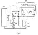
- FIG. 9 schematically the structure of a circuit arrangement for operating a high-pressure discharge lamp according to the preferred embodiments of the device according to the invention is shown.
- the circuit arrangement comprises a voltage converter 900, to whose DC output a storage capacitor 901 is connected.
- the storage capacitor 901 serves as a DC voltage source for a buck converter 910 connected thereto, which comprises the transistor 902, the inductance 903, the diode 904 and the pulse width modulation controller 905 for the transistor 902 and the capacitor 906.
- the DC output voltage of buck converter 910 is provided.
- the capacitor 906 serves as a voltage source for the full bridge inverter 920 connected thereto, which is formed essentially by the transistors 921, 922, 923 and 924.
- the high-pressure discharge lamp 930 and the ignitor 940 for the high-pressure discharge lamp 930 and the ignition monitoring circuit 941 are connected to the ignition timer 942.
- the resistors 951, 952, 953 serve to determine the instantaneous power consumption of the high-pressure discharge lamp 930.
- the measurement signals from the resistors 951, 952, 953 are supplied to the power control unit 960, which generates at its output a control signal for the pulse width modulation control 905 of the transistor 902.
- the power control unit 960 includes a regulator 961 with asymmetrical control characteristic. Two different embodiments of the controller 961 are in the Figures 3 and 6 shown schematically.
- the controller 961 can also be implemented as software in a program-controlled microcontroller for power control of the high-pressure discharge lamp.
- the power control of the high-pressure discharge lamp 930 is effected by the power control unit 960, the controller 961 and the pulse width modulation controller 905 by changing the turn-on and turn-off of the transistor 902 of the buck converter 910.
- the switching frequency of the transistor 902 and, accordingly, the pulse width modulation signals generated by the pulse width modulation controller 905 have a Frequency above 20 kHz.
- the high-pressure discharge lamp 930 is a halogen metal vapor high-pressure discharge lamp a rated power of 35 watts, which is intended as a light source for a motor vehicle headlight.
- circuit arrangement is therefore fed by the vehicle electrical system voltage of the motor vehicle.
- the transistor pairs 921, 924 and 922, 923 of the full-bridge inverter 920 alternately switch at a frequency of 500 hertz, so that the high-pressure discharge lamp 930 is supplied with a substantially rectangular, bipolar supply current of the same frequency.
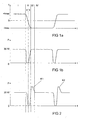
- FIG. 1a the time course of a substantially rectangular, bipolar supply current is shown schematically by means of a half-wave.
- the FIG. 1b shows the time course of the power consumption of the high pressure discharge lamp 930, the in FIG. 1a corresponds to the current waveform shown.
- Such a current or power curve is state of the art.
- commutation K1, K2 are also referred to as commutation K1, K2.
- the controller In the time intervals I and IV before and after the zero crossings of the supply current, the controller is in the steady state.
- the high pressure discharge lamp 930 operates near its rated power of 35 watts during time intervals I and IV.
- the pulse power of the commutation pulses K1, K2 and the power consumption during phases I and IV averaged over the entire period of the lamp current, a value of 35 watts.
- the commutation pulses K1, K2 during the time intervals III are generated and shaped by means of the asymmetric regulator 961, which is formed as part of the power regulation unit 960 serving to regulate the power consumption of the high-pressure discharge lamp 930.
- the controller 961 operates with two different controller characteristic curves, the first controller characteristic curve being only at a negative system deviation Xw, that is to say when the nominal power consumption falls below 35 watts, and the second controller characteristic curve is only at a positive system deviation Xw, that is, when the controller exceeds Setpoint power consumption of 35 watts is effective.
- the counter-control of the controller 961 by means of the second regulator characteristic is formed slower or slower compared to its counter-control means of the first regulator characteristic.
- the controller 961 therefore reacts to exceeding the power setpoint of 35 watts with a weaker counter-control than to an undershooting of the aforementioned power setpoint. He is thus asymmetrical.
- the first regulator characteristic of the regulator 961 is effective and during the time intervals III, the second regulator characteristic is effective.
- the 961 controller operates as a proportional-integral controller (PI controller) or as an integral controller (I-controller) with its first characteristic.
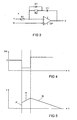
- the voltage on the capacitor 906 increases because of the inductance 903 stored energy during the time intervals IIa in the capacitor 906 discharges. This excessive voltage is available as a driving voltage during the time intervals IIb, to a steep increase in the current intensity of the supply current at the beginning of its negative half-wave and a shortening of the commutation time of the supply current and a steep increase in power consumption ( FIG. 2 ) to effect.
- second regulator characteristic of the controller 961 occurs during the time intervals III to a strong overshoot in power consumption and thus the formation of the power pulses K1, K2.
- the high-pressure discharge lamp 930 is an old lamp which forms comparatively long de-energized phases during the commutation, ie during the zero crossing of the supply current, the above effect is intensified.
- the controller 961 tries to increase the power consumption of the lamp with a fast counter-control according to its first regulator characteristic. This leads to a further increase of the driving voltage at the capacitor 906 and to a greater overshoot and to higher commutation pulses K1, K2.
- FIG. 3 schematically illustrates a circuit arrangement of the asymmetric regulator 961 according to the first embodiment.
- the regulator comprises an operational amplifier OP, two resistors R1, R2, a diode D1 and a capacitor C1.
- the controlled variable x is supplied via the resistor R1 to the inverting input of the operational amplifier OP.
- the non-inverting input of the operational amplifier OP, the setpoint w is supplied.
- the output y of the operational amplifier OP is coupled back to the inverting input of the operational amplifier via the capacitor C1 and the parallel connected in series with the capacitor C1, consisting of the diode D1 and the resistor R2.
- This controller is designed as an asymmetrical proportional-integral controller (PI controller).
- FIG. 5 is the response of this controller to the given as an example control deviation Xw according to the FIG. 4 shown schematically.
- the control deviation Xw is calculated as the difference between controlled variable x minus setpoint w.
- the controller In the case of a negative control deviation Xw, the controller generates a proportion P proportional to the amplitude of the control deviation Xw ( FIG. 5 ) of the manipulated variable y and a réelleh integral portion I1 of the manipulated variable y. This case corresponds to the above-mentioned first control characteristic of the controller 961. In the case of a positive control deviation Xw, the controller generates a second integral component I2 of the manipulated variable y. This case corresponds to the above-mentioned second control characteristic of the controller 961.
- Each according to the sign of the deviation Xw diode D1 is operated in the forward or reverse direction and accordingly a different time constant for the RC element in the feedback path between output y and inverting input of the operational amplifier OP and thus also another control characteristic is effective.
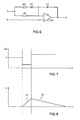
- FIG. 6 schematically illustrates a circuit arrangement of the asymmetric regulator 961 according to the second embodiment.
- the regulator comprises an operational amplifier OP, two resistors R1, R2, a diode D1 and a capacitor C1.
- the controlled variable x is supplied via the parallel connection of the resistor R1 with the series circuit of resistor R2 and diode D1 to the inverting input of the operational amplifier OP.
- the non-inverting input of the operational amplifier OP, the setpoint w is supplied.
- the output y of the operational amplifier OP is fed back via the capacitor C1 to the inverting input of the operational amplifier.
- This controller is designed as an asymmetric integral controller (I controller).
- FIG. 8 is the response of this controller to the given as an example control deviation Xw according to the FIG. 7 shown schematically.
- the control deviation Xw is calculated as the difference between controlled variable x minus setpoint w.
- the controller With a negative control deviation Xw, the controller generates a first integral component I1 'of the manipulated variable y. This case corresponds to the above-mentioned first control characteristic of the controller 961. In the case of a positive control deviation Xw, the controller generates a second integral component I2 'of the manipulated variable y. This case corresponds to the above-mentioned second control characteristic of the controller 961.
- the diode D1 is operated in the forward or reverse direction and corresponding to either the parallel connection of the resistors R1, R2 or only the resistor R1 for the calculation of the time constant of the RC element in the feedback branch between output y and inverting input of the operational amplifier OP, and thus also two different control characteristics for the controller, which are effective depending on the sign of the control deviation Xw.
- the asymmetrical regulator can also be realized by means of a microcontroller or microprocessor with implemented software, without the use of analog components.
Landscapes
- Circuit Arrangements For Discharge Lamps (AREA)
Abstract
Description
- Die Erfindung betrifft eine Vorrichtung zum Betreiben einer Hochdruckentladungslampe gemäß dem Oberbegriff des Patentanspruchs 1 und ein entsprechendes Betriebsverfahren.
- Eine derartige Vorrichtung ist beispielsweise auf den Seiten 217 und 218 in dem Buch "Betriebsgeräte und Schaltungen für elektrische Lampen" von C. H. Sturm und E. Klein, Siemens AG, 6. neubearbeitete Auflage 1992 beschrieben. Diese Textstelle offenbart den Betrieb einer Hochdruckentladungslampe mit einem bipolaren, im wesentlichen rechteckförmigen Versorgungsstrom mit Hilfe eines Vollbrückenwechselrichters, in dessen Brückenzweig die Hochdruckentladungslampe geschaltet ist.
- Hochdruckentladungslampen benötigen für ihren ordnungsgemäßen Betrieb einen definierten energetischen Haushalt. Ist ihr Energiehaushalt gestört, so kommt es zu Veränderungen im Betriebsverhalten der Hochdruckentladungslampe, beispielsweise zu einer Verkürzung der Lampenlebensdauer aufgrund von Elektrodenerosion oder Flickern verursacht durch einen undefinierten Entladungsbogenansatz. Bei dem Betrieb der Hochdruckentladungslampe mit einem bipolaren Versorgungsstrom stellt der Nulldurchgang des Versorgungsstroms bei seinem Polaritätswechsel eine kritische Betriebsphase der Lampe dar. Insbesondere bei Hochdruckentladungslampen mit vergleichsweise dicken Elektroden, die eine hohe Wärmeleitfähigkeiten besitzen, wie zum Beispiel bei quecksilberfreien Halogen-Metalldampf-Hochdruckentladungslampen, bewirkt der erhöhte Wärmetransport während des Nulldurchgangs des Versorgungsstroms eine entsprechend stärkere Abkühlung der Lampenelektroden.
- In diesem Fall kann die in die Hochdruckentladungslampe eingespeiste Leistung zu einer unzureichenden Aufheizung der Lampenelektroden vor dem Polaritätswechsel des Versorgungsstroms führen. Dementsprechend besitzen die Lampenelektroden eine verringerte Emissionsfähigkeit und die nach dem Polaritätswechsel verfügbare Spannung über dem Gesamtsystem, das heißt über dem Entladungsbogen und den Elektroden, reicht nicht aus, um den entsprechenden Stromfluss aufrecht zu erhalten bzw. schnellstmöglich bereitzustellen. An der Hochdruckentladungslampe lässt sich daher ein Flickern des Entladungsbogens beobachten. Dieses gilt insbesondere für stark gealterte Lampen. Um dieses Problem zu verringern wird gemäß der
EP 1 176 855 A2 in die Hochdruckentladungslampe, zeitnah zu dem Nulldurchgang ihres Versorgungsstroms, ein zusätzlicher Strom oder eine zusätzliche elektrische Leistung in Form eines Strom- oder Leistungsimpulses eingekoppelt. - Die
WO 2004/002200 A1 offenbart ein Verfahren zum Betreiben einer Entladungslampe mit einem Wechselstrom, dem ein Gleichstrom überlagert ist, um eine Temperaturdifferenz zwischen den Lampenelektroden zu kompensieren. - Es ist Aufgabe der Erfindung, eine gattungsgemäße Vorrichtung und ein entsprechendes Verfahren zum Betreiben einer Hochdruckentladungslampe bereitzustellen, welche die Formung des zusätzlichen Strom- oder Leistungsimpulses in die Hochdntekentladungslampe ermöglicht.
- Diese Aufgabe wird erfindungsgemäß durch die Merkmale des Patentanspruchs 1 bzw. 6 gelöst. Besonders vorteilhafte Ausführungen der Erfindung sind in den abhängigen Patentansprüchen beschrieben.
- Die erfindungsgemäße Vorrichtung zum Betreiben einer Hochdruckentladungslampe mit einem biploaren Versorgungsstrom und einer Leistungsregelung umfasst einen Regler mit einer asymmetrischen Regelungskennlinie zur Formung eines zeitnah zu dem Nulldurchgang des Versorgungsstroms angeordneten Strom- oder Leistungsimpulses. Mit Hilfe des asymmetrischen Reglers wird zeitnah zu dem Nulldurchgang des Versorgungsstroms, vorzugsweise unmittelbar nach dem Nulldurchgang des Versorgungsstroms, ein Strom- oder Leistungsimpuls generiert, indem der Regler dem durch die Kommutierung bedingten Absinken der Versorgungsstromstärke bzw. der Leistung unter einen vorgegebenen Sollwert sofort gegensteuert, um die Versorgungsstromstärke bzw. die Leistung wieder zu erhöhen. Der Regler der erfindungsgemäßen Vorrichtung besitzt eine asymmetrische Reglerkennlinie, so dass er auf ein Unterschreiten des Sollwerts des Betrags der Versorgungsstromstärke empfindlicher reagiert als auf ein Überschreiten des vorgenannten Sollwerts. Mit anderen Worten formuliert, der Regler ist so ausgebildet, dass er auf ein Unterschreiten des vorgenannten Sollwerts mit einer vergleichsweise schnelleren oder stärkeren Gegensteuerung reagiert als im Fall eines Überschreitens dieses Sollwerts. Dadurch wird mittels des Reglers unmittelbar nach jedem Nulldurchgang des bipolaren Versorgungsstroms eine Leistungsüberhöhung in Form eines so genannten Kommutierungsimpulses generiert. Die Form dieses Kommutierungsimpulses kann durch eine geeignete Dimensionierung der elektronischen Bauteile des Reglers beeinflusst werden. Durch die vergleichsweise schnelle oder starke Gegensteuerung des Reglers im Fall des Unterschreitens des oben genannten Sollwerts wird ein Überschwingen verursacht, das den Anstieg und die Höhe des Kommutierungsimpulses nach dem Nulldurchgang des Versorgungsstroms bestimmt. Durch die vergleichsweise, träge Gegensteuerung des Reglers im Fall des Überschreitens des oben genannten Sollwerts wird bei der abfallenden Flanke des Kommutierungspulses das Auftreten von Oszillationen verhindert.
- Der asymmetrische Regler ist vorteilhafterweise an die Leistungsregelungseinrichtung gekoppelt, die zur Regelung der Leistungsaufnahme der Hochdruckentladungslampe auf ein konstantes Niveau dient. Dadurch kann der asymmetrische Regler unmittelbar in die Leistungsregelung der Hochdruckentladungslampe eingreifen. Alternativ kann zur Regelung auch der Lampenstrom der Hochdruckentladungslampe herangezogen werden. Vorzugsweise wird die Leistungsregelung mittels einer Pulsweitenmodulation durchgeführt und der asymmetrische Reglers ist daher vorzugsweise an eine Pulsweitenmodulationssteuerung zur Leistungsregelung der Hochdruckentladungslampe gekoppelt.
- Gemäß dem bevorzugten Ausführungsbeispiel der Erfindung umfasst die Vorrichtung einen Halb- oder Vollbrückenwechselrichter, in dessen Brückenzweig die Hochdruckentladungslampe geschaltet ist, um diese mit einem bipolaren Strom niedriger Frequenz von üblicherweise kleiner als 1000 Hertz zu versorgen.
- Der Regler ist vorzugsweise entweder als asymmetrischer Proportional-Integral-Regler (PI-Regler) oder als asymmetrischer Integral-Regler (I-Regler) ausgebildet.
- Nachstehend wird die Erfindung anhand von bevorzugten Ausführungsbeispielen näher erläutert. Es zeigen:
- Figur 1
- a) Eine schematische Darstellung des zeitlichen Verlaufs des Versor- gungsstroms für die Hochdruckentladungslampe, ohne Regelung mittels des asymmetrischen Reglers
- Figur 1
- b) Eine schematische Darstellung des zeitlichen Verlaufs der Leistungs- aufnahme der Hochdruckentladungslampe, ohne Regelung mittels des a- symmetrischen Reglers
- Figur 2
- Eine schematische Darstellung des zeitlichen Verlaufs der momentanen Leistungsaufnahme der Hochdruckentladungslampe mit vom asymmetri- schen Regler geformten Kommutierungsimpulsen unmittelbar nach jedem Nulldurchgang des Versorgungsstroms
- Figur 3
- Eine Schaltskizze eines asymmetrischen Reglers gemäß dem ersten Aus- führungsbeispiel der Erfindung
- Figur 4
- Eine schematische Darstellung des zeitlichen Verlaufs einer Regelabwei- chung
- Figur 5
- Eine schematische Darstellung der Antwort des Reglers gemäß der
Figur 3 auf die Regelanweichung gemäß derFigur 4 - Figur 6
- Eine Schaltskizze eines asymmetrischen Reglers gemäß dem zweiten Aus- führungsbeispiel der Erfindung
- Figur 7
- Eine schematische Darstellung des zeitlichen Verlaufs einer Regelabwei- chung
- Figur 8
- Eine schematische Darstellung der Antwort des Reglers gemäß der
Figur 6 auf die Regelanweichung gemäß derFigur 7 - Figur 9
- Eine Schaltskizze der Schaltungsanordnung zum Betrieb einer Hoch- druckentladungslampe gemäß dem bevorzugten Ausführungsbeispiel der Erfindung
- In
Figur 9 ist schematisch der Aufbau einer Schaltungsanordnung zum Betrieb einer Hochdruckentladungslampe entsprechend den bevorzugten Ausführungsbeispielen der erfindungsgemäßen Vorrichtung dargestellt. Die Schaltungsanordnung umfasst einen Spannungswandler 900, an dessen Gleichspannungsausgang ein Speicherkondensator 901 angeschlossen ist. Der Speicherkondensator 901 dient als Gleichspannungsquelle für einen daran angeschlossenen Tiefsetzsteller 910, der den Transistor 902, die Induktivität 903, die Diode 904 und die Pulsweitenmodulationssteuerung 905 für den Transistor 902 sowie den Kondensator 906 umfasst. Am Kondensator 906 wird die Ausgangsgleichspannung des Tiefsetzstellers 910 bereitgestellt. Der Kondensator 906 dient als Spannungsquelle für den daran angeschlossenen Vollbrückenwechselrichter 920, der im wesentlichen von den Transistoren 921, 922, 923 und 924 gebildet wird. In den Brückenzweig des Vollbrückenwechselrichters 920 sind die Hochdruckentladungslampe 930 und das Zündgerät 940 für die Hochdruckentladungslampe 930 sowie die Zündüberwachungsschaltung 941 mit dem Zündzeitgeber 942 geschaltet. Die Widerstände 951, 952, 953 dienen zur Ermittlung der momentanen Leistungsaufnahme der Hochdruckentladungslampe 930. Die Messsignale von den Widerständen 951, 952, 953 werden der Leistungsregelungseinheit 960 zugeführt, die an ihrem Ausgang ein Steuerungssignal für die Pulsweitenmodulationssteuerung 905 des Transistors 902 erzeugt. Die Leistungsregelungseinheit 960 umfasst einen Regler 961 mit asymmetrischer Regelungskennlinie. Zwei unterschiedliche Ausführungsbeispiele des Reglers 961 sind in denFiguren 3 und6 schematisch dargestellt. Der Regler 961 kann aber auch als Software in einem programmgesteuert arbeitenden Mikrocontroller zur Leistungsregelung der Hochdruckentladungslampe implementiert sein. Die Leistungsregelung der Hochdruckentladungslampe 930 erfolgt mittels der Leistungsregelungseinheit 960, des Reglers 961 und der Pulsweitenmodulationssteuerung 905 über ein Verändern der Ein- und Ausschaltdauer des Transistors 902 des Tiefsetzstellers 910. Die Schaltfrequenz des Transistors 902 und dementsprechend auch die von der Pulsweitenmodulationssteuerung 905 generierten Pulsweitenmodulationssignale besitzen eine Frequenz oberhalb von 20 kHz. - Bei der Hochdruckentladungslampe 930 handelt es sich gemäß der bevorzugten Ausführungsbeispiele um eine Halogen-Metalldampf-Hochdruckentladungslampe mit einer Nennleistung von 35 Watt, die als Lichtquelle für einen Kraftfahrzeugscheinwerfer vorgesehen ist. Die in
Figur 9 abgebildete Schaltungsanordnung wird daher von der Bordnetzspannung des Kraftfahrzeugs gespeist. - Die Transistorpaare 921, 924 und 922, 923 des Vollbrückenwechselrichters 920 schalten alternierend mit einer Frequenz von 500 Hertz, so dass die Hochdruckentladungslampe 930 mit einem im wesentlichen rechteckförmigen, bipolaren Versorgungsstrom derselben Frequenz gespeist wird. In
Figur 1a ist der zeitliche Verlauf eines im wesentlichen rechteckförmigen, bipolaren Versorgungsstroms anhand einer Halbwelle schematisch dargestellt. DieFigur 1b zeigt den zeitlichen Verlauf der Leistungsaufnahme der Hochdruckentladungslampe 930, der dem inFigur 1a dargestellten Stromverlauf entspricht. Ein derartiger Strom- bzw. Leistungsverlauf ist Stand der Technik. Mittels des asymmetrischen Reglers, der erfindungsgemäß als Bestandteil der Betriebsvorrichtung ausgebildet ist, werden in den Zeitintervallen III Stromimpulse erzeugt, die dem im wesentlichen rechteckförmigen, bipolaren Versorgungsstrom überlagert sind und unmittelbar nach jedem Nulldurchgang des Versorgungsstroms auftreten. Diese Stromimpulse befinden sich in Phase mit in den gleichen Zeitintervallen auftretenden Leistungsimpulsen K1, K2, die zu den Stromimpulsen korrespondieren. In derFigur 2 ist daher nur der zeitliche Verlauf der momentanen elektrischen Leistungsaufnahme der Hochdruckentladungslampe 930 dargestellt, der mittels der erfindungsgemäßen Vorrichtung erzeugt wird. Die zu den Leistungsimpulsen K1, K2 korrespondierenden Stromimpulse besitzen abwechselnd negative und positive Polarität und ihre maximale Stromstärke ist größer als die Amplitude Imax des rechteckförmigen Versorgungsstroms. Die Stromimpulse bzw. Leistungsimpulse (inFigur 2 dargestellt) werden auch als Kommutierungsimpulse K1, K2 bezeichnet. In den Zeitintervallen I und IV vor und nach den Nulldurchgängen des Versorgungsstroms befindet sich der Regler im eingeschwungenen Zustand. Die Hochdruckentladungslampe 930 wird während der Zeitintervalle I und IV nahe ihrer Nennleistung von 35 Watt betrieben. Die Impulsleistung der Kommutierungsimpulse K1, K2 und die Leistungsaufnahme während der Phasen I und IV ergeben über die gesamte Periode des Lampenstroms gemittelt einen Wert von 35 Watt. - Die Kommutierungsimpulse K1, K2 während der Zeitintervalle III werden mit Hilfe des asymmetrischen Reglers 961 erzeugt und geformt, der als Bestandteil der zur Regelung der Leistungsaufnahme der Hochdruckentladungslampe 930 dienenden Leistungsregelungseinheit 960 ausgebildet ist. Der Regler 961 arbeitet mit zwei unterschiedlichen Reglerkennlinien, wobei die erste Reglerkennlinie nur bei einer negativen Regelabweichung Xw, das heißt, beim Unterschreiten des Sollwerts der Leistungsaufnahme von 35 Watt, und die zweite Reglerkennlinie nur bei einer positiven Regelabweichung Xw, das heißt, beim Überschreiten des Sollwerts der Leistungsaufnahme von 35 Watt wirksam ist. Die Gegensteuerung des Reglers 961 mittels der zweiten Reglerkennlinie ist im Vergleich zu seiner Gegensteuerung mittels der ersten Reglerkennlinie langsamer bzw. träger ausgebildet. Der Regler 961 reagiert daher auf eine Überschreitung des Leistungssollwerts von 35 Watt mit einer schwächeren Gegensteuerung als auf eine Unterschreitung des vorgenannten Leistungssollwerts. Er ist somit asymmetrisch ausgebildet. Während der Zeitintervalle IIa, IIb (
Figuren 1 und 2 ) ist die erste Reglerkennlinie des Reglers 961 wirksam und während der Zeitintervalle III ist die zweite Reglerkennlinie wirksam. - Sinkt im nicht-leitenden Zustand der Vollbrücke 920 der Versorgungsstrom zu Beginn der Zeitintervalle IIa, so dass die momentane Leistungsaufnahme der Hochdruckentladungslampe 930 unter den Sollwert von 35 Watt abfällt, so erfolgt mittels des asymmetrischen Reglers 961 eine sofortige Gegensteuerung. Der Regler 961 arbeitet als Proportional-Integral-Regler (PI-Regler) oder als Integral-Regler (I-Regler) mit seiner ersten Kennlinie. Da die getaktete Stromversorgung 910, 920 der Hochdruckentladungslampe 930 während der Zeitintervalle IIa aufgrund der nicht-leitenden Vollbrücke 920 auf eine Last gegen Null (d.h. ihr Widerstandswert geht gegen unendlich) arbeitet,erhöht sich die Spannung am Kondensator 906, weil sich die in der Induktivität 903 gespeicherte Energie während der Zeitintervalle IIa in den Kondensator 906 entlädt. Diese überhöhte Spannung steht während der Zeitintervalle IIb als treibende Spannung zur Verfügung, um einen steilen Anstieg der Stromstärke des Versorgungsstroms zu Beginn seiner negativen Halbwelle und eine Verkürzung der Kommutierungszeit des Versorgungsstroms sowie einen steilen Anstieg der Leistungsaufnahme (
Figur 2 ) zu bewirken. In Verbindung mit der während der Zeitintervalle IIb wirkenden ersten Reglerkennlinie des Reglers 961 und der während der Zeitintervalle III wirkenden zweiten Reglerkennlinie des Reglers 961 kommt es während der Zeitintervalle III zu einem starken Überschwingen der Leistungsaufnahme und somit zur Entstehung der Leistungsimpulse K1, K2. Handelt es sich bei der Hochdruckentladungslampe 930 um eine alte Lampe, die vergleichsweise lange stromlose Phasen während der Kommutierung, d.h. während des Nulldurchgangs des Versorgungsstroms, ausbildet, so verstärkt sich der obige Effekt. Der Regler 961 versucht mit einer schnellen Gegensteuerung gemäß seiner ersten Reglerkennlinie die Leistungsaufnahme der Lampe weiter zu erhöhen. Das führt zu einer weiteren Erhöhung der treibenden Spannung am Kondensator 906 und zu einem stärkeren Überschwingen sowie zu höheren Kommutierungsimpulsen K1, K2. - In
Figur 3 ist schematisch eine Schaltungsanordnung des asymmetrischen Reglers 961 gemäß dem ersten Ausführungsbeispiel abgebildet. Der Regler umfasst einen Operationsverstärker OP, zwei Widerstände R1, R2, eine Diode D1 und einen Kondensator C1. Die Regelgröße x wird über den Widerstand R1 dem invertierenden Eingang des Operationsverstärkers OP zugeführt. Dem nicht-invertierenden Eingang des Operationsverstärkers OP wird der Sollwert w zugeführt. Der Ausgang y des Operationsverstärkers OP ist über den Kondensator C1 und die in Serie zum Kondensator C1 geschaltete Parallelschaltung, bestehend aus der Diode D1 und dem Widerstand R2, zum invertierenden Eingang des Operationsverstärkers zurückgekoppelt. Dieser Regler ist als asymmetrischer Proportional-Integral-Regler (PI-Regler) ausgebildet. InFigur 5 ist die Antwort dieses Reglers auf die als Beispiel vorgegebene Regelabweichung Xw gemäß derFigur 4 schematisch dargestellt. Die Regelabweichung Xw berechnet sich als Differenz von Regelgröße x minus Sollwert w. - Bei negativer Regelabweichung Xw erzeugt der Regler einen der Amplitude der Regelabweichung Xw proportionalen Anteil P (
Figur 5 ) der Stellgröße y und einen ersteh integralen Anteil I1 der Stellgröße y. Dieser Fall entspricht der oben erwähnten ersten Regelungskennlinie des Reglers 961. Im Fall einer positiven Regelabweichung Xw erzeugt der Regler einen zweiten integralen Anteil I2 der Stellgröße y. Dieser Fall entspricht der oben erwähnten zweiten Regelungskennlinie des Reglers 961. Je nach Vorzeichen der Regelabweichung Xw wird die Diode D1 in Durchlass- oder Sperrrichtung betrieben und dem entsprechend ist eine andere Zeitkonstante für das RC-Glied im Rückkopplungszweig zwischen Ausgang y und invertierendem Eingang des Operationsverstärkers OP und somit auch eine andere Regelungskennlinie wirksam. - In
Figur 6 ist schematisch eine Schaltungsanordnung des asymmetrischen Reglers 961 gemäß dem zweiten Ausführungsbeispiel abgebildet. Der Regler umfasst einen Operationsverstärker OP, zwei Widerstände R1, R2, eine Diode D1 und einen Kondensator C1. Die Regelgröße x wird über die Parallelschaltung des Widerstands R1 mit der Serienschaltung von Widerstand R2 und Diode D1 dem invertierenden Eingang des Operationsverstärkers OP zugeführt. Dem nicht-invertierenden Eingang des Operationsverstärkers OP wird der Sollwert w zugeführt. Der Ausgang y des Operationsverstärkers OP ist über den Kondensator C1 zum invertierenden Eingang des Operationsverstärkers zurückgekoppelt. Dieser Regler ist als asymmetrischer Integral-Regler (I-Regler) ausgebildet. InFigur 8 ist die Antwort dieses Reglers auf die als Beispiel vorgegebene Regelabweichung Xw gemäß derFigur 7 schematisch dargestellt. Die Regelabweichung Xw berechnet sich als Differenz von Regelgröße x minus Sollwert w. - Bei negativer Regelabweichung Xw erzeugt der Regler einen ersten integralen Anteil I1' der Stellgröße y. Dieser Fall entspricht der oben erwähnten ersten Regelungskennlinie des Reglers 961. Im Fall einer positiven Regelabweichung Xw erzeugt der Regler einen zweiten integralen Anteil I2' der Stellgröße y. Dieser Fall entspricht der oben erwähnten zweiten Regelungskennlinie des Reglers 961. Je nach Vorzeichen der Regelabweichung Xw wird die Diode D1 in Durchlass- oder Sperrrichtung betrieben und dem entsprechend ist entweder die Parallelschaltung der Widerstände R1, R2 oder nur der Widerstand R1 für die Berechnung der Zeitkonstante des RC-Gliedes im Rückkopplungszweig zwischen Ausgang y und invertierendem Eingang des Operationsverstärkers OP heranzuziehen und somit ergeben sich auch zwei unterschiedliche Regelungskennlinien für den Regler, die je nach Vorzeichen der Regelabweichung Xw wirksam sind.
- Die Erfindung beschränkt sich nicht auf die näher erläuterten Ausführungsbeispiele. Beispielsweise kann der asymmetrische Regler auch mittels eines Mikrocontrollers oder Mikroprozessors mit implementierter Software, ohne Verwendung analoger Bauteile, verwirklicht werden.
Claims (6)
- Vorrichtung zum Betreiben einer Hochdruckentladungslampe (930) mit einem bipolaren Versorgungsstrom und einer geregelten Leistungsaufnahme, wobei die Vorrichtung einen Reglers zur Formung eines zeitnah zu dem Nulldurchgang des Versorgungsstroms angeordneten Strom- oder Leistungsimpulses (K1,K2) umfasst, dadurch gekennzeichnet, dass der Regler (961) eine asymmetrische Regelungskennlinie besitzt, so dass er auf ein Unterschreiten eines vorgegebenen Sollwerts des Betrags der Versorgungsstromstärke mit einer vergleichsweise schnelleren oder stärkeren Gegensteuerung reagiert als im Fall eines Überschreitens dieses Sollwerts.
- Vorrichtung nach Anspruch 1, dadurch gekennzeichnet, dass der Regler (961) als asymmetrischer PI-Regler ausgebildet ist.
- Vorrichtung nach Anspruch 1, dadurch gekennzeichnet, dass der Regler (961) als asymmetrischer I-Regler ausgebildet ist.
- Vorrichtung nach Anspruch 1, dadurch gekennzeichnet, dass der asymmetrische Regler (961) an eine Pulsweitenmodulationssteuerung (905) zur Leistungsregelung der Hochdruckentladungslampe (930) gekoppelt ist.
- Vorrichtung nach einem oder mehreren der vorstehenden Ansprüche, dadurch gekennzeichnet, dass die Vorrichtung einen Voll- oder Halbbrückenwechseirichter (920) umfasst, in dessen Brückenzweig die Hochdruckentladungslampe (930) geschaltet ist.
- Verfahren zum Betreiben einer Hochdruckentladungslampe (930) mit einem bipolaren Versorgungsstrom und einer Regelung der Leistungsaufnahme, bei der zeitnah zu den Nulldurchgängen des Versorgungsstroms Strom- oder Leistungsimpulse (K1, K2) geformt werden, dadurch gekennzeichnet, dass die Regelung der Leistungsaufnahme mit Hilfe einer asymmetrischen Regelungskennlinie durchgeführt wird, so dass auf ein Unterschreiten eines vorgegebenen Sollwerts des Betrags der Versorgungsstromstärke mit einer vergleichsweise schnelleren oder stärkeren Gegensteuerung reagiert wird als im Fall eines Überschreitens dieses Sollwerts.
Applications Claiming Priority (2)
| Application Number | Priority Date | Filing Date | Title |
|---|---|---|---|
| DE102005031835A DE102005031835A1 (de) | 2005-07-06 | 2005-07-06 | Vorrichtung zum Betreiben einer Hochdruckentladungslampe |
| PCT/DE2006/001133 WO2007003171A1 (de) | 2005-07-06 | 2006-06-30 | Vorrichtung und verfahren zum betreiben einer hochdruckentladungslampe |
Publications (2)
| Publication Number | Publication Date |
|---|---|
| EP1900262A1 EP1900262A1 (de) | 2008-03-19 |
| EP1900262B1 true EP1900262B1 (de) | 2009-12-30 |
Family
ID=37075598
Family Applications (1)
| Application Number | Title | Priority Date | Filing Date |
|---|---|---|---|
| EP06753295A Not-in-force EP1900262B1 (de) | 2005-07-06 | 2006-06-30 | Vorrichtung und verfahren zum betreiben einer hochdruckentladungslampe |
Country Status (7)
| Country | Link |
|---|---|
| US (1) | US8111002B2 (de) |
| EP (1) | EP1900262B1 (de) |
| JP (1) | JP4700732B2 (de) |
| CN (1) | CN101213883B (de) |
| CA (1) | CA2614004A1 (de) |
| DE (2) | DE102005031835A1 (de) |
| WO (1) | WO2007003171A1 (de) |
Families Citing this family (3)
| Publication number | Priority date | Publication date | Assignee | Title |
|---|---|---|---|---|
| DE102007060035A1 (de) | 2007-12-05 | 2009-06-10 | Osram Gesellschaft mit beschränkter Haftung | Vorrichtung und Verfahren zum Betreiben einer Hochdruckentladungslampe |
| DE102010039430A1 (de) * | 2010-08-18 | 2012-02-23 | Osram Ag | Elektronisches Vorschaltgerät und Verfahren zum Betreiben mindestens einer Entladungslampe |
| EP2526741B1 (de) * | 2010-11-08 | 2014-04-30 | OSRAM GmbH | Schaltungsanordnung und verfahren zur schnellen kommutierung beim rechteckbetrieb von hochdruckentladungslampen |
Family Cites Families (19)
| Publication number | Priority date | Publication date | Assignee | Title |
|---|---|---|---|---|
| DE4301184C2 (de) * | 1993-01-19 | 1997-12-18 | B & S Elektronische Geraete Gm | Steuergerät für wenigstens eine Entladungslampe |
| US5428268A (en) * | 1993-07-12 | 1995-06-27 | Led Corporation N.V. | Low frequency square wave electronic ballast for gas discharge |
| JP3447776B2 (ja) * | 1993-09-17 | 2003-09-16 | 池田デンソー株式会社 | 放電灯点灯装置 |
| DE4410177A1 (de) * | 1994-03-24 | 1995-09-28 | Hella Kg Hueck & Co | Vorschaltgerät zum Starten und Betreiben von Wechselstrom-Hochdruck-Gasentladungslampen |
| US6225754B1 (en) * | 1996-10-21 | 2001-05-01 | Matsushita Electric Industrial Co., Ltd. | Operating method and operating apparatus for a high pressure discharge lamp |
| KR19990068269A (ko) * | 1999-01-02 | 1999-09-06 | 김중성 | 마이크로프로세서를이용한고압방전등용전자식안정기 |
| US6166495A (en) * | 1999-04-14 | 2000-12-26 | Osram Sylvania Inc. | Square wave ballast for mercury free arc lamp |
| JP3871033B2 (ja) * | 2000-03-09 | 2007-01-24 | 三菱電機株式会社 | 放電灯点灯装置及びランプ装置 |
| JP4426132B2 (ja) | 2000-07-26 | 2010-03-03 | ハリソン東芝ライティング株式会社 | 高圧放電ランプ点灯方法、高圧放電ランプ点灯装置および照明装置 |
| JP4308454B2 (ja) * | 2001-07-16 | 2009-08-05 | パナソニック電工株式会社 | 放電灯点灯装置 |
| US6552498B1 (en) * | 2001-09-28 | 2003-04-22 | Osram Sylvania Inc. | Method and circuit for controlling current in a high pressure discharge lamp |
| CN1663325A (zh) * | 2002-06-25 | 2005-08-31 | 皇家飞利浦电子股份有限公司 | 气体放电灯的操作 |
| JP4171285B2 (ja) * | 2002-11-06 | 2008-10-22 | フェニックス電機株式会社 | 高圧放電灯の点灯方法および点灯装置 |
| JP4325620B2 (ja) * | 2003-01-17 | 2009-09-02 | パナソニック電工株式会社 | 放電灯点灯装置、照明装置、プロジェクタ |
| JP2004296427A (ja) * | 2003-03-13 | 2004-10-21 | Ushio Inc | 超高圧水銀ランプ発光装置 |
| US7622869B2 (en) * | 2004-02-24 | 2009-11-24 | Panasonic Electric Works Co., Ltd. | Discharge lamp ballast and projector |
| JP4241515B2 (ja) * | 2004-06-10 | 2009-03-18 | パナソニック電工株式会社 | 放電灯点灯装置及びプロジェクタ |
| KR100627704B1 (ko) * | 2004-09-22 | 2006-09-25 | 삼성전자주식회사 | 램프전류 검출 기능과 트랜스포머 2 차측 전압 검출기능을 가지는 방전램프 구동회로 및 방전램프 구동방법 |
| US7221107B2 (en) * | 2005-04-13 | 2007-05-22 | Ballastronic, Inc. | Low frequency electronic ballast for gas discharge lamps |
-
2005
- 2005-07-06 DE DE102005031835A patent/DE102005031835A1/de not_active Withdrawn
-
2006
- 2006-06-30 DE DE502006005792T patent/DE502006005792D1/de active Active
- 2006-06-30 US US11/988,367 patent/US8111002B2/en not_active Expired - Fee Related
- 2006-06-30 JP JP2008519792A patent/JP4700732B2/ja not_active Expired - Fee Related
- 2006-06-30 CA CA002614004A patent/CA2614004A1/en not_active Abandoned
- 2006-06-30 WO PCT/DE2006/001133 patent/WO2007003171A1/de not_active Ceased
- 2006-06-30 CN CN2006800244264A patent/CN101213883B/zh not_active Expired - Fee Related
- 2006-06-30 EP EP06753295A patent/EP1900262B1/de not_active Not-in-force
Also Published As
| Publication number | Publication date |
|---|---|
| DE102005031835A1 (de) | 2007-01-18 |
| JP4700732B2 (ja) | 2011-06-15 |
| EP1900262A1 (de) | 2008-03-19 |
| US8111002B2 (en) | 2012-02-07 |
| CA2614004A1 (en) | 2007-01-11 |
| DE502006005792D1 (de) | 2010-02-11 |
| CN101213883A (zh) | 2008-07-02 |
| CN101213883B (zh) | 2012-08-08 |
| JP2008545244A (ja) | 2008-12-11 |
| WO2007003171A1 (de) | 2007-01-11 |
| US20090278468A1 (en) | 2009-11-12 |
Similar Documents
| Publication | Publication Date | Title |
|---|---|---|
| EP2420107B1 (de) | Leistungsregelung von led, mittels mittelwert des led-stroms und bidirektionaler zähler | |
| EP2915240B1 (de) | Verfahren zum steuern eines akkubetriebenen schweissgeräts und akkubetriebenes schweissgerät | |
| EP3262896B1 (de) | Schaltregler zum betreiben von leuchtmitteln mit spitzenstromwertsteuerung und mittelstromwerterfassung | |
| EP3202235B1 (de) | Getakteter elektronischer energiewandler mit einstellbarer lückenzeit | |
| EP3308604B1 (de) | Getaktete sperrwandlerschaltung | |
| DE102005006587B4 (de) | Wechselrichter insbesondere für eine konstante Lichtabgabe einer Kaltkathodenfluoreszenzlampe und Verfahren zum Betrieb dieses Wechselrichters | |
| EP2292079B1 (de) | Lampentyperkennung durch leistunsfaktorkorrekturschaltung | |
| EP1872627B1 (de) | Parametrisierbarer digitaler pfc | |
| EP2837092B1 (de) | Verfahren zum regeln einer leistungsfaktorkorrekturschaltung, leistungsfaktorkorrekturschaltung und betriebsgerät für ein leuchtmittel | |
| DE102014106869B4 (de) | LED-Beleuchtungsvorrichtung und Beleuchtungsgerät | |
| EP2859652B1 (de) | Leistungsfaktorkorrekturschaltung, betriebsgerät für ein leuchtmittel und verfahren zum steuern einer leistungsfaktorkorrekturschaltung | |
| AT16163U1 (de) | Lampenbetriebsgerät | |
| EP1900262B1 (de) | Vorrichtung und verfahren zum betreiben einer hochdruckentladungslampe | |
| EP2327276B1 (de) | Schaltungsanordnung und verfahren zum betreiben einer entladungslampe | |
| EP1901592B1 (de) | Elektronisches Vorschaltgerät mit asymmetrischer Wechselrichter-Ansteuerung | |
| EP1395096B1 (de) | Verfahren zum Betreiben von Leuchtstofflampen und Vorschaltgerät | |
| DE102016107578B4 (de) | Betriebsschaltung und Verfahren zum Betreiben wenigstens eines Leuchtmittels | |
| DE102004037389B4 (de) | Verfahren zur Ansteuerung einer eine Leuchtstofflampe aufweisenden Last zur Optimierung des Zündvorganges | |
| EP1994805B1 (de) | Schaltungsanordnung und verfahren zum betreiben einer hochdruckentladungslampe | |
| DE102006010502A1 (de) | Entladungslampen-Versorgungsschaltung | |
| EP2421336A1 (de) | Elektronisches Vorschaltgerät und Verfahren zum betreiben mindestens einer Entladungslampe | |
| EP1713309A2 (de) | Schaltung und Verfahren zum Betreiben von Miniatur-Hochdruck-Kurzbogenlampen mit Wechselstrom | |
| EP2005804B1 (de) | Schaltungsanordnung und verfahren zum betreiben einer entladungslampe | |
| DE102011000441A1 (de) | Betriebssteuergerät und Verfahren zum Dimmen eines Leuchtmittels über die Versorgungsspannung und die Spannungsfrequenz | |
| DE202018104924U1 (de) | Lampenbetriebsgerät mit Konverter in DCM |
Legal Events
| Date | Code | Title | Description |
|---|---|---|---|
| PUAI | Public reference made under article 153(3) epc to a published international application that has entered the european phase |
Free format text: ORIGINAL CODE: 0009012 |
|
| 17P | Request for examination filed |
Effective date: 20071122 |
|
| AK | Designated contracting states |
Kind code of ref document: A1 Designated state(s): DE FR GB HU IT |
|
| DAX | Request for extension of the european patent (deleted) | ||
| RBV | Designated contracting states (corrected) |
Designated state(s): DE FR GB HU IT |
|
| 17Q | First examination report despatched |
Effective date: 20080716 |
|
| GRAP | Despatch of communication of intention to grant a patent |
Free format text: ORIGINAL CODE: EPIDOSNIGR1 |
|
| RAP1 | Party data changed (applicant data changed or rights of an application transferred) |
Owner name: OSRAM GESELLSCHAFT MIT BESCHRAENKTER HAFTUNG |
|
| GRAS | Grant fee paid |
Free format text: ORIGINAL CODE: EPIDOSNIGR3 |
|
| GRAA | (expected) grant |
Free format text: ORIGINAL CODE: 0009210 |
|
| AK | Designated contracting states |
Kind code of ref document: B1 Designated state(s): DE FR GB HU IT |
|
| REG | Reference to a national code |
Ref country code: GB Ref legal event code: FG4D Free format text: NOT ENGLISH |
|
| REF | Corresponds to: |
Ref document number: 502006005792 Country of ref document: DE Date of ref document: 20100211 Kind code of ref document: P |
|
| REG | Reference to a national code |
Ref country code: HU Ref legal event code: AG4A Ref document number: E007322 Country of ref document: HU |
|
| PLBE | No opposition filed within time limit |
Free format text: ORIGINAL CODE: 0009261 |
|
| STAA | Information on the status of an ep patent application or granted ep patent |
Free format text: STATUS: NO OPPOSITION FILED WITHIN TIME LIMIT |
|
| 26N | No opposition filed |
Effective date: 20101001 |
|
| GBPC | Gb: european patent ceased through non-payment of renewal fee |
Effective date: 20100630 |
|
| REG | Reference to a national code |
Ref country code: FR Ref legal event code: ST Effective date: 20110228 |
|
| PG25 | Lapsed in a contracting state [announced via postgrant information from national office to epo] |
Ref country code: IT Free format text: LAPSE BECAUSE OF FAILURE TO SUBMIT A TRANSLATION OF THE DESCRIPTION OR TO PAY THE FEE WITHIN THE PRESCRIBED TIME-LIMIT Effective date: 20091230 |
|
| PG25 | Lapsed in a contracting state [announced via postgrant information from national office to epo] |
Ref country code: FR Free format text: LAPSE BECAUSE OF NON-PAYMENT OF DUE FEES Effective date: 20100630 |
|
| PG25 | Lapsed in a contracting state [announced via postgrant information from national office to epo] |
Ref country code: GB Free format text: LAPSE BECAUSE OF NON-PAYMENT OF DUE FEES Effective date: 20100630 |
|
| REG | Reference to a national code |
Ref country code: DE Ref legal event code: R081 Ref document number: 502006005792 Country of ref document: DE Owner name: OSRAM GMBH, DE Free format text: FORMER OWNER: OSRAM GESELLSCHAFT MIT BESCHRAENKTER HAFTUNG, 81543 MUENCHEN, DE Effective date: 20111213 |
|
| REG | Reference to a national code |
Ref country code: DE Ref legal event code: R081 Ref document number: 502006005792 Country of ref document: DE Owner name: OSRAM GMBH, DE Free format text: FORMER OWNER: OSRAM AG, 81543 MUENCHEN, DE Effective date: 20130205 |
|
| REG | Reference to a national code |
Ref country code: DE Ref legal event code: R081 Ref document number: 502006005792 Country of ref document: DE Owner name: OSRAM GMBH, DE Free format text: FORMER OWNER: OSRAM GMBH, 81543 MUENCHEN, DE Effective date: 20130823 |
|
| PGFP | Annual fee paid to national office [announced via postgrant information from national office to epo] |
Ref country code: HU Payment date: 20170616 Year of fee payment: 12 |
|
| PG25 | Lapsed in a contracting state [announced via postgrant information from national office to epo] |
Ref country code: HU Free format text: LAPSE BECAUSE OF NON-PAYMENT OF DUE FEES Effective date: 20180701 |
|
| PGFP | Annual fee paid to national office [announced via postgrant information from national office to epo] |
Ref country code: DE Payment date: 20190619 Year of fee payment: 14 |
|
| REG | Reference to a national code |
Ref country code: DE Ref legal event code: R119 Ref document number: 502006005792 Country of ref document: DE |
|
| PG25 | Lapsed in a contracting state [announced via postgrant information from national office to epo] |
Ref country code: DE Free format text: LAPSE BECAUSE OF NON-PAYMENT OF DUE FEES Effective date: 20210101 |