EP1899196B1 - Nightvisionsystem - Google Patents
Nightvisionsystem Download PDFInfo
- Publication number
- EP1899196B1 EP1899196B1 EP06763144A EP06763144A EP1899196B1 EP 1899196 B1 EP1899196 B1 EP 1899196B1 EP 06763144 A EP06763144 A EP 06763144A EP 06763144 A EP06763144 A EP 06763144A EP 1899196 B1 EP1899196 B1 EP 1899196B1
- Authority
- EP
- European Patent Office
- Prior art keywords
- vision system
- night vision
- image
- display
- image recording
- Prior art date
- Legal status (The legal status is an assumption and is not a legal conclusion. Google has not performed a legal analysis and makes no representation as to the accuracy of the status listed.)
- Expired - Lifetime
Links
Images

Classifications
-
- B—PERFORMING OPERATIONS; TRANSPORTING
- B60—VEHICLES IN GENERAL
- B60R—VEHICLES, VEHICLE FITTINGS, OR VEHICLE PARTS, NOT OTHERWISE PROVIDED FOR
- B60R11/00—Arrangements for holding or mounting articles, not otherwise provided for
- B60R11/04—Mounting of cameras operative during drive; Arrangement of controls thereof relative to the vehicle
-
- B—PERFORMING OPERATIONS; TRANSPORTING
- B60—VEHICLES IN GENERAL
- B60R—VEHICLES, VEHICLE FITTINGS, OR VEHICLE PARTS, NOT OTHERWISE PROVIDED FOR
- B60R1/00—Optical viewing arrangements; Real-time viewing arrangements for drivers or passengers using optical image capturing systems, e.g. cameras or video systems specially adapted for use in or on vehicles
- B60R1/20—Real-time viewing arrangements for drivers or passengers using optical image capturing systems, e.g. cameras or video systems specially adapted for use in or on vehicles
- B60R1/22—Real-time viewing arrangements for drivers or passengers using optical image capturing systems, e.g. cameras or video systems specially adapted for use in or on vehicles for viewing an area outside the vehicle, e.g. the exterior of the vehicle
- B60R1/23—Real-time viewing arrangements for drivers or passengers using optical image capturing systems, e.g. cameras or video systems specially adapted for use in or on vehicles for viewing an area outside the vehicle, e.g. the exterior of the vehicle with a predetermined field of view
- B60R1/24—Real-time viewing arrangements for drivers or passengers using optical image capturing systems, e.g. cameras or video systems specially adapted for use in or on vehicles for viewing an area outside the vehicle, e.g. the exterior of the vehicle with a predetermined field of view in front of the vehicle
-
- B—PERFORMING OPERATIONS; TRANSPORTING
- B60—VEHICLES IN GENERAL
- B60R—VEHICLES, VEHICLE FITTINGS, OR VEHICLE PARTS, NOT OTHERWISE PROVIDED FOR
- B60R1/00—Optical viewing arrangements; Real-time viewing arrangements for drivers or passengers using optical image capturing systems, e.g. cameras or video systems specially adapted for use in or on vehicles
- B60R1/20—Real-time viewing arrangements for drivers or passengers using optical image capturing systems, e.g. cameras or video systems specially adapted for use in or on vehicles
- B60R1/22—Real-time viewing arrangements for drivers or passengers using optical image capturing systems, e.g. cameras or video systems specially adapted for use in or on vehicles for viewing an area outside the vehicle, e.g. the exterior of the vehicle
- B60R1/28—Real-time viewing arrangements for drivers or passengers using optical image capturing systems, e.g. cameras or video systems specially adapted for use in or on vehicles for viewing an area outside the vehicle, e.g. the exterior of the vehicle with an adjustable field of view
-
- B—PERFORMING OPERATIONS; TRANSPORTING
- B60—VEHICLES IN GENERAL
- B60R—VEHICLES, VEHICLE FITTINGS, OR VEHICLE PARTS, NOT OTHERWISE PROVIDED FOR
- B60R1/00—Optical viewing arrangements; Real-time viewing arrangements for drivers or passengers using optical image capturing systems, e.g. cameras or video systems specially adapted for use in or on vehicles
- B60R1/20—Real-time viewing arrangements for drivers or passengers using optical image capturing systems, e.g. cameras or video systems specially adapted for use in or on vehicles
- B60R1/30—Real-time viewing arrangements for drivers or passengers using optical image capturing systems, e.g. cameras or video systems specially adapted for use in or on vehicles providing vision in the non-visible spectrum, e.g. night or infrared vision
-
- B—PERFORMING OPERATIONS; TRANSPORTING
- B60—VEHICLES IN GENERAL
- B60R—VEHICLES, VEHICLE FITTINGS, OR VEHICLE PARTS, NOT OTHERWISE PROVIDED FOR
- B60R11/00—Arrangements for holding or mounting articles, not otherwise provided for
- B60R2011/0001—Arrangements for holding or mounting articles, not otherwise provided for characterised by position
- B60R2011/0003—Arrangements for holding or mounting articles, not otherwise provided for characterised by position inside the vehicle
- B60R2011/0019—Side or rear panels
- B60R2011/0022—Pillars
-
- B—PERFORMING OPERATIONS; TRANSPORTING
- B60—VEHICLES IN GENERAL
- B60R—VEHICLES, VEHICLE FITTINGS, OR VEHICLE PARTS, NOT OTHERWISE PROVIDED FOR
- B60R11/00—Arrangements for holding or mounting articles, not otherwise provided for
- B60R2011/0001—Arrangements for holding or mounting articles, not otherwise provided for characterised by position
- B60R2011/004—Arrangements for holding or mounting articles, not otherwise provided for characterised by position outside the vehicle
-
- B—PERFORMING OPERATIONS; TRANSPORTING
- B60—VEHICLES IN GENERAL
- B60R—VEHICLES, VEHICLE FITTINGS, OR VEHICLE PARTS, NOT OTHERWISE PROVIDED FOR
- B60R11/00—Arrangements for holding or mounting articles, not otherwise provided for
- B60R2011/0042—Arrangements for holding or mounting articles, not otherwise provided for characterised by mounting means
- B60R2011/008—Adjustable or movable supports
-
- B—PERFORMING OPERATIONS; TRANSPORTING
- B60—VEHICLES IN GENERAL
- B60R—VEHICLES, VEHICLE FITTINGS, OR VEHICLE PARTS, NOT OTHERWISE PROVIDED FOR
- B60R2300/00—Details of viewing arrangements using cameras and displays, specially adapted for use in a vehicle
- B60R2300/10—Details of viewing arrangements using cameras and displays, specially adapted for use in a vehicle characterised by the type of camera system used
- B60R2300/101—Details of viewing arrangements using cameras and displays, specially adapted for use in a vehicle characterised by the type of camera system used using cameras with adjustable capturing direction
-
- B—PERFORMING OPERATIONS; TRANSPORTING
- B60—VEHICLES IN GENERAL
- B60R—VEHICLES, VEHICLE FITTINGS, OR VEHICLE PARTS, NOT OTHERWISE PROVIDED FOR
- B60R2300/00—Details of viewing arrangements using cameras and displays, specially adapted for use in a vehicle
- B60R2300/10—Details of viewing arrangements using cameras and displays, specially adapted for use in a vehicle characterised by the type of camera system used
- B60R2300/106—Details of viewing arrangements using cameras and displays, specially adapted for use in a vehicle characterised by the type of camera system used using night vision cameras
-
- B—PERFORMING OPERATIONS; TRANSPORTING
- B60—VEHICLES IN GENERAL
- B60R—VEHICLES, VEHICLE FITTINGS, OR VEHICLE PARTS, NOT OTHERWISE PROVIDED FOR
- B60R2300/00—Details of viewing arrangements using cameras and displays, specially adapted for use in a vehicle
- B60R2300/30—Details of viewing arrangements using cameras and displays, specially adapted for use in a vehicle characterised by the type of image processing
- B60R2300/307—Details of viewing arrangements using cameras and displays, specially adapted for use in a vehicle characterised by the type of image processing virtually distinguishing relevant parts of a scene from the background of the scene
- B60R2300/308—Details of viewing arrangements using cameras and displays, specially adapted for use in a vehicle characterised by the type of image processing virtually distinguishing relevant parts of a scene from the background of the scene by overlaying the real scene, e.g. through a head-up display on the windscreen
-
- B—PERFORMING OPERATIONS; TRANSPORTING
- B60—VEHICLES IN GENERAL
- B60R—VEHICLES, VEHICLE FITTINGS, OR VEHICLE PARTS, NOT OTHERWISE PROVIDED FOR
- B60R2300/00—Details of viewing arrangements using cameras and displays, specially adapted for use in a vehicle
- B60R2300/80—Details of viewing arrangements using cameras and displays, specially adapted for use in a vehicle characterised by the intended use of the viewing arrangement
- B60R2300/8053—Details of viewing arrangements using cameras and displays, specially adapted for use in a vehicle characterised by the intended use of the viewing arrangement for bad weather conditions or night vision
Definitions
- the invention relates to a night vision system night vision system in which an image capture unit captures the image of the surroundings of a motor vehicle, the captured image is processed in an image processing device and displayed in a display.
- an image capture unit captures the image of the surroundings of a motor vehicle
- the captured image is processed in an image processing device and displayed in a display.
- infrared cameras are present as image capture units and the image taken by the infrared cameras is displayed on a display.
- the infrared cameras have specific lenses, so that the display is fixed on the display at a certain angle.
- a night vision system according to the preamble of claim 1 is known from DE-A-199 50 033 known .
- the object of the invention is therefore to provide a night vision system of the aforementioned type, in which the image detail is adapted to the current driving task and the information needs of the driver.
- This object is achieved by a night vision system with the features of claim 1.
- the image capture device advantageously pivots vertically such that it can pick up more distant objects that can then be displayed by the display.
- the night vision system are information on the type of the road used, for example, in which it is coupled to a navigation system, or in which the recorded images are evaluated accordingly and a corresponding road type is classified, and according to the type of road, the image capture unit is pivoted vertically accordingly.
- the image capture unit is set to detect the area closer to the motor vehicle, and in road types where high speeds are usually traveled, the image capture unit is panned so that it is more distant Objects can be recorded. If the horizontal position of the image acquisition unit is also changed, the information can be further improved. In particular, if the horizontal position of the image acquisition unit is changed depending on the course of the road. Thus, objects can be perceived that are not in a straight line in front of the motor vehicle, but are at a corresponding winding road at another point on the road.
- an image capture unit can advantageously find an infrared camera use.
- objects can be displayed which are located in the area of the normal headlights. It is also possible to detect objects that may also be outside the range of headlights by their heat radiation and display on the display.
- the performance of the infrared cameras can still be increased.
- the image capture device as a radar
- the function is less disturbed in bad environmental conditions, such as heavy rain or snowfall, than in an infrared system.
- the display is designed as a head-up display, the driver of the motor vehicle is the least distracted because the display is projected as a virtual image on the windshield of the motor vehicle and so the display simultaneously with the real events in front of the motor vehicle can be perceived.
- the display it is also possible to provide the display as a separate component and to provide, for example, in the center console or in the combination instrument of the motor vehicle. However, the driver is prevented, at the same time to see directly on the road.
- FIG. 1 One recognizes the part of a motor vehicle 1 and a motor driver K.
- the motor vehicle has an image capture device 2, which is vertically pivotable about an axis A1 and horizontal about an axis A2, as is illustrated by the double arrows 3, 4.
- the motor vehicle 1 furthermore has a projection unit of a head-up display 5 and a windshield 6. That of the image capture device 2 recorded image is either processed in an image processing device, not shown, and projected on the projection unit 5 of the head-up display on the windshield 6, or transmitted directly from the image capture device 2 to the projection unit 5 of the head-up display and then to the windshield 6 projected.
- the driver can perceive the image taken by the image capturing device 3 and projected onto the windshield 6 as an imaginary image i perceivable by the driver behind the windshield 6. Due to the configuration as a head-up display, the motorist can simultaneously perceive the information recorded by the image capture device and at the same time the real environment located in front of the motor vehicle.
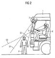
- FIG. 2 one recognizes a person P, who is staying directly in front of the motor vehicle 1 and is located below the line S3, which limits the field of vision of the driver down. Thus, the person P is in the blind spot and can not be perceived by the driver K directly. Since the motor vehicle is stationary, the image capturing device 2 is pivoted vertically downward, so that its detection range, which is limited by the beams S1 and S2, captures the reality directly in front of the motor vehicle 1. Thus, the person P is projected onto the windshield via the head-up display, and the driver can perceive that the person P is in front of his motor vehicle.
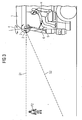
- the motor vehicle 1 has an average speed, so that the image capture device 1 assumes a nearly horizontal position, so that it detects the area bounded by the beams S1, S2. So she can take the picture of person P2.
- the image thus captured is projected onto the windscreen 6 via the projection unit 5 of the head-up display, so that the driver can perceive the image of the person as an imaginary image, even if the person is out of range of the headlights of the motor vehicle.
- the invention can of course also be presented with a different display. However, the driver must take his eyes off the lane in front of the vehicle so that he can not perceive the real reality at the same time.
Landscapes
- Engineering & Computer Science (AREA)
- Multimedia (AREA)
- Mechanical Engineering (AREA)
- Closed-Circuit Television Systems (AREA)
- Instrument Panels (AREA)
- Traffic Control Systems (AREA)
- Fittings On The Vehicle Exterior For Carrying Loads, And Devices For Holding Or Mounting Articles (AREA)
- Detergent Compositions (AREA)
- Agricultural Chemicals And Associated Chemicals (AREA)
- Navigation (AREA)
- Devices For Indicating Variable Information By Combining Individual Elements (AREA)
Description
- Die Erfindung betrifft ein Nightvisionsystem Nachtsichtsystem, bei dem eine Bilderfassungseinheit das Bild der Umgebung eines Kraftfahrzeuges aufnimmt, das aufgenommene Bild in einer Bildverarbeitungseinrichtung verarbeitet wird und in einer Anzeige dargestellt wird. Aus dem Stand der Technik sind derartige Systeme bekannt, bei dem Infrarotkameras als Bilderfassungseinheiten vorhanden sind und das von den Infrarotkameras aufgenommene Bild auf einem Display dargestellt wird. Hierbei weisen die Infrarotkameras spezifische Objektive auf, so dass die Darstellung auf dem Display auf einen bestimmten Blickwinkel fixiert ist. Hierdurch ist eine Anpassung des Bildausschnitts an eine aktuelle Fahraufgabe und das Informationsbedürfnis des Fahrers bzw. der Fahrerin nicht möglich.
- Ein Nightvisionsystem nach dem Oberbegriff des Anspruchs 1 ist aus der
DE-A-199 50 033 bekannt. - Aufgabe der Erfindung ist es daher, ein Nightvisionsystem der vorgenannten Art anzugeben, bei der der Bildausschnitt an die aktuelle Fahraufgabe und das Informationsbedürfnis des Fahrers angepasst wird. Diese Aufgabe wird von einem Nightvisionsystem mit den Merkmalen des Anspruchs 1 gelöst. Durch die Veränderung der Lage der Bilderfassungseinrichtung wird eine für die jeweilige Fahrsituation optimale Lage der Bilderfassungseinrichtung und damit der Anzeige der Umgebung des Kraftfahrzeuges erreicht. Besonders vorteilhaft ist es, die Bilderfassungseinrichtung in Abhängigkeit der gefahrenen Geschwindigkeit vertikal zu verschwenken. So wird im Stillstand und bei niedrigen Geschwindigkeiten die Bilderfassungseinrichtung so verschwenkt, dass der Bereich direkt vor dem Fahrzeug optimal wahrgenommen werden kann. Dies ist insbesondere bei Nutzfahrzeugen vorteilhaft, bei denen der Kraftfahrer bzw. die Kraftfahrerin sehr hoch über der Fahrbahn sitzen und den Bereich direkt vor dem Fahrzeug selbst trotz vorhandener Beleuchtung nicht einsehen können, da hier ein toter Winkel vorhanden ist. Mit zunehmender Geschwindigkeit orientieren sich die Kraftfahrer bzw. Kraftfahrerinnen üblicherweise in weiter entfernte Regionen vor dem Kraftfahrzeug, damit sie bei auftretenden Hindernissen entsprechend reagieren können. Deshalb wird bei zunehmender Geschwindigkeit die Bilderfassungseinrichtung vorteilhafterweise derart vertikal verschwenkt, dass sie weiter entfernte Objekte aufnehmen kann, die dann mittels der Anzeige darstellbar sind. Erfindungsgemäß liegen dem Nightvisionsystem Informationen über den Typ der befahrenen Straße vor, beispielsweise in dem es mit einem Navigationssystem gekoppelt ist, oder in dem die aufgenommenen Bilder entsprechend ausgewertet werden und ein entsprechender Straßentyp klassifiziert wird, und entsprechend dem Straßentyp wird die Bilderfassungseinheit entsprechend vertikal verschwenkt. Insbesondere derart, dass bei Straßentypen mit üblicherweise niedrigen Geschwindigkeiten die Bilderfassungseinheit derart eingestellt wird, dass der Bereich erfasst wird, der näher vor dem Kraftfahrzeug liegt, und bei Straßentypen, bei denen üblicherweise hohe Geschwindigkeiten gefahren werden, die Bilderfassungseinheit derart geschwenkt ist, dass entfernter liegende Objekte aufgenommen werden können. Wenn auch die horizontale Lage der Bilderfassungseinheit verändert wird, kann die Information weiter verbessert werden. Insbesondere, wenn die horizontale Lage der Bilderfassungseinheit in Abhängigkeit des Straßenverlaufs verändert wird. So können Objekte wahrgenommen werden, die sich nicht in gerader Linie vor dem Kraftfahrzeug befinden, sondern bei einem entsprechenden kurvigen Straßenverlauf an einer anderen Stelle auf der Straße befinden.
- Als Bilderfassungseinheit kann vorteilhafter Weise eine Infrarotkamera Verwendung finden. Hierdurch können zum einen Objekte dargestellt werden, die sich im Bereich der normalen Scheinwerfer befinden. Auch ist es möglich, Objekte, die sich auch außerhalb des Bereiches von Scheinwerfern befinden können, durch ihre Wärmestrahlung zu erfassen und auf der Anzeige darzustellen.
- Wenn eine Infrarotbeleuchtungsvorrichtung vorhanden ist, kann die Leistung der Infrarotkameras noch erhöht werden. Bei einer Ausgestaltung der Bilderfassungseinrichtung als Radar wird die Funktion bei schlechten Umwelteinflüssen, wie beispielsweise starkem Regen oder Schneefall, weniger gestört als bei einem Infrarotsystem.
- Wenn die Anzeige als Head-up-Display ausgestaltet ist, wird der Fahrer bzw. die Fahrerin des Kraftfahrzeuges am wenigsten abgelenkt, da die Anzeige als virtuelles Bild auf die Windschutzscheibe des Kraftfahrzeuges projiziert wird und so die Anzeige gleichzeitig mit dem realen Geschehen vor dem Kraftfahrzeug wahrgenommen werden kann. Natürlich ist es auch möglich, die Anzeige als separates Bauteil vorzusehen und beispielsweise in der Mittelkonsole oder im Kombinationsinstrument des Kraftfahrzeuges vorzusehen. Dabei wird der Kraftfahrer aber gehindert, gleichzeitig direkt auf die Fahrbahn zu sehen.
- Die Erfindung wird nachfolgend anhand der Figuren näher erläutert. Es zeigen:
- Figur 1
- den Teil eines Kraftfahrzeuges mit einem Ausfüh- rungsbeispiel eines erfindungsgemäßen Nightvision- system,
- Figur 2
- das Kraftfahrzeug aus
Figur 1 , bei dem die Bilder- fassungseinheit vertikal nach unten verschwenkt ist, - Figur 3
- das Kraftfahrzeug aus
Figur 1 , bei dem die Bilder- fassungseinheit des Nightvisionsystems vertikal nach oben verschwenkt ist. - In
Figur 1 erkennt man den Teil eines Kraftfahrzeuges 1 und einen Kraftfahrer K. Das Kraftfahrzeug weist eine Bilderfassungseinrichtung 2 auf, die vertikal um eine Achse A1 und horizontal um eine Achse A2 verschwenkbar ist, wie durch die Doppelpfeile 3, 4 verdeutlicht wird. Das Kraftfahrzeug 1 weist weiterhin eine Projektionseinheit eines Head-up-Displays 5 und eine Windschutzscheibe 6 auf. Das von der Bilderfassungseinrichtung 2 aufgenommene Bild wird entweder in einer nicht dargestellten Bildverarbeitungseinrichtung bearbeitet und über die Projektionseinheit 5 des Head-up-Displays auf die Windschutzscheibe 6 projiziert, oder direkt von der Bilderfassungseinrichtung 2 an die Projektionseinheit 5 des Head-up-Display übermittelt und dann auf die Windschutzscheibe 6 projiziert. Der Kraftfahrer kann das von der Bilderfassungseinrichtung 3 aufgenommene und auf die Windschutzscheibe 6 projizierte Bild als imaginäres Bild i wahrnehmen, das für den Kraftfahrer hinter der Windschutzscheibe 6 wahrnehmbar ist. Durch die Ausgestaltung als Head-up-Display kann der Kraftfahrer gleichzeitig die von der Bilderfassungseinrichtung aufgenommene Information und gleichzeitig die vor dem Kraftfahrzeug befindliche reale Umwelt wahrnehmen. - In
Figur 2 erkennt man eine Person P, die sich direkt vor dem Kraftfahrzeug 1 aufhält und sich unterhalb der Linie S3 befindet, die den Sichtbereich des Kraftfahrers nach unten begrenzt. Somit befindet sich die Person P im toten Winkel und kann von dem Kraftfahrer K direkt nicht wahrgenommen werden. Da das Kraftfahrzeug steht, ist die Bilderfassungseinrichtung 2 vertikal nach unten geschwenkt, so dass ihr Erfassüngsbereich, der durch die Strahlen S1 und S2 begrenzt wird, die Realität direkt vor dem Kraftfahrzeug 1 aufnimmt. So wird die Person P über das Head-up-Display auf die Windschutzscheibe projiziert, und der Kraftfahrer kann wahrnehmen, dass sich vor seinem Kraftfahrzeug die Person P befindet. - In
Figur 3 weist das Kraftfahrzeug 1 eine mittlere Geschwindigkeit auf, so dass die Bilderfassungseinrichtung 1 eine nahezu waagerechte Position einnimmt, so dass sie den Bereich erfasst, der durch die Strahlen S1, S2 begrenzt wird. So kann sie das Bild der Person P2 aufnehmen. Das so aufgenommene Bild wird über die Projektionseinheit 5 des Head-up-Displays auf die Windschutzscheibe 6 projiziert, so dass der Kraftfahrer das Bild der Person als imaginäres Bild wahrnehmen kann, auch wenn sich die Person außerhalb der Reichweite der Scheinwerfer des Kraftfahrzeuges befindet. Die Erfindung kann selbstverständlich auch mit einer anderen Anzeige dargestellt werden. Hierbei muss der Kraftfahrer aber seinen Blick von der vor dem Fahrzeug befindlichen Fahrbahn nehmen, so dass er sich die real darstellende Wirklichkeit nicht gleichzeitig wahrnehmen kann.
Claims (8)
- Nightvisionsystem; bei dem eine Bilderfassungseinheit das Bild der Umgebung eines Kraftfahrzeuges aufnimmt, das aufgenommene Bild mittels einer Anzeige dargestellt wird, wobei die Lage der Bilderfassungseinrichtung (2) in Abhängigkeit der Fahrsituation verändert wird, dadurch gekennzeichnet, dass die vertikale Verstellbarket der Bilderfassungseinrichtung (2) auch von dem befahrenen Straßentyp abhängt.
- Nightvisionsystem nach Anspruch 1, dadurch gekennzeichnet, dass die Bilderfassungseinrichtung (2) in Abhängigkeit der gefahrenen Geschwindigkeit vertikal verschwenkt wird.
- Nightvisionsystem nach einem der vorstehenden Ansprüche, dadurch gekennzeichnet, dass die horizontale Lage der Bilderfassungseinrichtung (2) verändert wird.
- Nightvisionsystem nach Anspruch 3, dadurch gekennzeichnet, dass die horizontale Lage der Bilderfassungseinrichtung (2) in Abhängigkeit des Straßenverlaufs verändert wird.
- Nightvisionsystem nach einem der vorstehenden Ansprüche, dadurch gekennzeichnet, dass die Bilderfassungseinrichtung (2) als Infrarotkamera ausgestaltet ist.
- Nightvisionsystem nach Anspruch 5, dadurch gekennzeichnet, dass eine Infrarotbeleuchtungsvorrichtung vorhanden ist.
- Nightvisionsystem nach einem der vorstehenden Ansprüche, dadurch gekennzeichnet, dass die Bilderfassungseinrichtung (2) als Radar ausgestaltet ist.
- Nightvisionsystem nach einem der vorstehenden Ansprüche, dadurch gekennzeichnet, dass die Anzeige als Head-up-Display (5) ausgestaltet ist.
Applications Claiming Priority (2)
| Application Number | Priority Date | Filing Date | Title |
|---|---|---|---|
| DE102005030838A DE102005030838A1 (de) | 2005-07-01 | 2005-07-01 | Nightvisionsystem |
| PCT/EP2006/062292 WO2007003463A1 (de) | 2005-07-01 | 2006-05-15 | Nightvisionsystem |
Publications (2)
| Publication Number | Publication Date |
|---|---|
| EP1899196A1 EP1899196A1 (de) | 2008-03-19 |
| EP1899196B1 true EP1899196B1 (de) | 2010-01-27 |
Family
ID=36693123
Family Applications (1)
| Application Number | Title | Priority Date | Filing Date |
|---|---|---|---|
| EP06763144A Expired - Lifetime EP1899196B1 (de) | 2005-07-01 | 2006-05-15 | Nightvisionsystem |
Country Status (9)
| Country | Link |
|---|---|
| US (1) | US8878932B2 (de) |
| EP (1) | EP1899196B1 (de) |
| JP (1) | JP2008545188A (de) |
| CN (1) | CN101213110B (de) |
| AT (1) | ATE456486T1 (de) |
| BR (1) | BRPI0612979A2 (de) |
| CA (1) | CA2613863A1 (de) |
| DE (2) | DE102005030838A1 (de) |
| WO (1) | WO2007003463A1 (de) |
Families Citing this family (13)
| Publication number | Priority date | Publication date | Assignee | Title |
|---|---|---|---|---|
| DE102007042966A1 (de) * | 2007-09-10 | 2009-04-09 | Continental Automotive Gmbh | Vorrichtung zur Darstellung der Information der Einparkhilfe eines Kraftfahrzeuges |
| EP2156987A1 (de) * | 2008-08-22 | 2010-02-24 | Guangzhou SAT Infrared Technology Co., Ltd. | Infrarotsystem zur Unterstützung des Fahrers eines Fahrzeugs |
| IT1392979B1 (it) * | 2009-02-23 | 2012-04-02 | Ansaldobreda Spa | Veicolo ferroviario provvisto di un sistema video interno |
| CN102951091A (zh) * | 2011-08-18 | 2013-03-06 | 上海博泰悦臻电子设备制造有限公司 | 车载增视装置 |
| CN102658798B (zh) * | 2012-05-07 | 2014-11-05 | 奇瑞汽车股份有限公司 | 一种车载夜视系统及其控制方法 |
| CN104149701B (zh) * | 2014-08-28 | 2016-02-24 | 吉林大学 | 无盲区汽车雷达控制系统 |
| JP6707948B2 (ja) * | 2016-03-29 | 2020-06-10 | いすゞ自動車株式会社 | ドライブレコーダ |
| DE102018202195B4 (de) | 2018-02-13 | 2023-04-20 | Ibeo Automotive Systems GmbH | Verfahren zur Ausrichtung eines optischen Sensors |
| US11772574B2 (en) * | 2018-05-03 | 2023-10-03 | Volvo Truck Corporation | Vehicle comprising a driver cab and a monitoring device for monitoring a front dead angle area and monitoring device for such vehicle |
| EP3967559B1 (de) * | 2020-09-09 | 2023-06-07 | Volvo Truck Corporation | Verfahren und system zur verwaltung eines assistenzsystems für eine windschutzscheibe eines fahrerhauses eines fahrzeugs |
| JP7409544B1 (ja) | 2023-03-28 | 2024-01-09 | いすゞ自動車株式会社 | 運転支援装置 |
| JP7414175B1 (ja) | 2023-03-28 | 2024-01-16 | いすゞ自動車株式会社 | 運転支援装置 |
| JP7414176B1 (ja) | 2023-03-28 | 2024-01-16 | いすゞ自動車株式会社 | 運転支援装置 |
Family Cites Families (42)
| Publication number | Priority date | Publication date | Assignee | Title |
|---|---|---|---|---|
| US5172317A (en) * | 1988-08-10 | 1992-12-15 | Honda Giken Kogyo Kabushiki Kaisha | Automatic travelling apparatus |
| JPH05174296A (ja) * | 1991-12-20 | 1993-07-13 | Mitsubishi Motors Corp | 車間距離検知・警報装置 |
| US6150930A (en) * | 1992-08-14 | 2000-11-21 | Texas Instruments Incorporated | Video equipment and method to assist motor vehicle operators |
| JPH09270098A (ja) * | 1996-04-02 | 1997-10-14 | Mitsubishi Motors Corp | 車線逸脱警報装置 |
| JPH11312300A (ja) | 1998-04-27 | 1999-11-09 | Matsushita Electric Ind Co Ltd | 車載カメラ |
| JP4114292B2 (ja) * | 1998-12-03 | 2008-07-09 | アイシン・エィ・ダブリュ株式会社 | 運転支援装置 |
| CN1126969C (zh) | 1999-03-08 | 2003-11-05 | 戴巍 | 机动车夜视装置 |
| JP3298851B2 (ja) * | 1999-08-18 | 2002-07-08 | 松下電器産業株式会社 | 多機能車載カメラシステムと多機能車載カメラの画像表示方法 |
| DE19950033B4 (de) * | 1999-10-16 | 2005-03-03 | Bayerische Motoren Werke Ag | Kameravorrichtung für Fahrzeuge |
| US6515597B1 (en) * | 2000-01-31 | 2003-02-04 | Matsushita Electric Industrial Co. Ltd. | Vicinity display for car |
| DE10203413C2 (de) * | 2002-01-28 | 2003-11-27 | Daimler Chrysler Ag | Automobiles Infrarot-Nachtsichtgerät |
| US7016518B2 (en) * | 2002-03-15 | 2006-03-21 | Extreme Cctv Inc. | Vehicle license plate imaging and reading system for day and night |
| US7774113B2 (en) * | 2002-04-10 | 2010-08-10 | Trw Limited | Cameras to determine vehicle heading |
| EP1497155B1 (de) * | 2002-04-23 | 2006-08-16 | Autoliv Development Ab | Nachtsichtanordnung |
| US7834905B2 (en) | 2002-06-18 | 2010-11-16 | Bayerische Motoren Werke Aktiengesellschaft | Method and system for visualizing the environment of a vehicle with a distance-dependent merging of an infrared and a visual image |
| US6725139B2 (en) * | 2002-08-19 | 2004-04-20 | Ford Global Technologies, Llc | Steerable night vision system |
| JP2004082918A (ja) * | 2002-08-28 | 2004-03-18 | Ichikoh Ind Ltd | 車両用暗視装置及びルームミラー |
| DE10255797A1 (de) * | 2002-11-28 | 2004-06-17 | Daimlerchrysler Ag | Verfahren zur Erfassung der vorausliegenden Umgebung eines Strassenfahrzeugs mittels eines Umgebungserfassungssystems |
| JP4093094B2 (ja) * | 2003-03-25 | 2008-05-28 | 株式会社デンソー | 車両周辺監視システム及び車両周辺監視方法 |
| KR100482598B1 (ko) * | 2003-04-21 | 2005-04-14 | 현대자동차주식회사 | 차간거리 제어방법 및 장치 |
| WO2004106856A1 (ja) * | 2003-05-29 | 2004-12-09 | Olympus Corporation | ステレオカメラ支持装置、ステレオカメラ支持方法及びキャリブレーション検出装置及びキャリブレーション補正装置並びにステレオカメラシステム |
| JP3987013B2 (ja) * | 2003-09-01 | 2007-10-03 | 本田技研工業株式会社 | 車両周辺監視装置 |
| JP4161861B2 (ja) * | 2003-09-12 | 2008-10-08 | 日産自動車株式会社 | 曲線道路用前照灯に連動した車両用暗視装置 |
| DE10343479A1 (de) | 2003-09-19 | 2005-04-28 | Bosch Gmbh Robert | Verfahren zur Verbesserung der Sicht in einem Kraftfahrzeug |
| US7319805B2 (en) * | 2003-10-06 | 2008-01-15 | Ford Motor Company | Active night vision image intensity balancing system |
| JP3925488B2 (ja) * | 2003-11-11 | 2007-06-06 | 日産自動車株式会社 | 車両用画像処理装置 |
| US20050146458A1 (en) * | 2004-01-07 | 2005-07-07 | Carmichael Steve D. | Vehicular electronics interface module and related methods |
| DE102004013252A1 (de) * | 2004-03-18 | 2005-10-06 | Robert Bosch Gmbh | Verfahren und Vorrichtung zur Sichtverbesserung bei einem Fahrzeug |
| US7190282B2 (en) * | 2004-03-26 | 2007-03-13 | Mitsubishi Jidosha Kogyo Kabushiki Kaisha | Nose-view monitoring apparatus |
| JP3934119B2 (ja) * | 2004-06-14 | 2007-06-20 | 本田技研工業株式会社 | 車両周辺監視装置 |
| JP3987057B2 (ja) * | 2004-06-14 | 2007-10-03 | 本田技研工業株式会社 | 車両周辺監視装置 |
| US7561719B2 (en) * | 2004-11-30 | 2009-07-14 | Honda Motor Co., Ltd. | Vehicle surroundings monitoring apparatus |
| JP4650079B2 (ja) * | 2004-11-30 | 2011-03-16 | 日産自動車株式会社 | 物体検出装置、および方法 |
| KR100708470B1 (ko) * | 2005-02-28 | 2007-04-18 | 삼성전자주식회사 | 감시 카메라의 팬/틸트모터 제어 장치 및 그 제어 방법 |
| US8130269B2 (en) * | 2005-03-23 | 2012-03-06 | Aisin Aw Co., Ltd. | Visual recognition apparatus, methods, and programs for vehicles |
| DE102005041535A1 (de) * | 2005-08-31 | 2007-03-01 | Siemens Ag | Night-Vision-System, bei dem die Umgebung mittels einer Aufnahmevorrichtung aufgenommen und mittels einer Anzeige zumindest teilweise dargestellt wird |
| US8164628B2 (en) * | 2006-01-04 | 2012-04-24 | Mobileye Technologies Ltd. | Estimating distance to an object using a sequence of images recorded by a monocular camera |
| US8139109B2 (en) * | 2006-06-19 | 2012-03-20 | Oshkosh Corporation | Vision system for an autonomous vehicle |
| JP4855158B2 (ja) * | 2006-07-05 | 2012-01-18 | 本田技研工業株式会社 | 運転支援装置 |
| US8218007B2 (en) * | 2007-09-23 | 2012-07-10 | Volkswagen Ag | Camera system for a vehicle and method for controlling a camera system |
| US8289189B2 (en) * | 2009-05-11 | 2012-10-16 | Robert Bosch Gmbh | Camera system for use in vehicle parking |
| JP5188452B2 (ja) * | 2009-05-22 | 2013-04-24 | 富士重工業株式会社 | 道路形状認識装置 |
-
2005
- 2005-07-01 DE DE102005030838A patent/DE102005030838A1/de not_active Ceased
-
2006
- 2006-05-15 BR BRPI0612979-0A patent/BRPI0612979A2/pt not_active IP Right Cessation
- 2006-05-15 JP JP2008518772A patent/JP2008545188A/ja active Pending
- 2006-05-15 CA CA002613863A patent/CA2613863A1/en not_active Abandoned
- 2006-05-15 EP EP06763144A patent/EP1899196B1/de not_active Expired - Lifetime
- 2006-05-15 CN CN200680023939.3A patent/CN101213110B/zh not_active Expired - Fee Related
- 2006-05-15 AT AT06763144T patent/ATE456486T1/de active
- 2006-05-15 US US11/994,011 patent/US8878932B2/en not_active Expired - Fee Related
- 2006-05-15 WO PCT/EP2006/062292 patent/WO2007003463A1/de not_active Ceased
- 2006-05-15 DE DE502006006045T patent/DE502006006045D1/de not_active Expired - Lifetime
Also Published As
| Publication number | Publication date |
|---|---|
| CN101213110B (zh) | 2011-03-09 |
| CA2613863A1 (en) | 2007-01-11 |
| US8878932B2 (en) | 2014-11-04 |
| DE502006006045D1 (en) | 2010-03-18 |
| EP1899196A1 (de) | 2008-03-19 |
| US20080198227A1 (en) | 2008-08-21 |
| BRPI0612979A2 (pt) | 2010-12-14 |
| CN101213110A (zh) | 2008-07-02 |
| WO2007003463A1 (de) | 2007-01-11 |
| ATE456486T1 (de) | 2010-02-15 |
| JP2008545188A (ja) | 2008-12-11 |
| DE102005030838A1 (de) | 2007-01-04 |
Similar Documents
| Publication | Publication Date | Title |
|---|---|---|
| DE102017103287B4 (de) | Anzeigesteuerung für ein fahrzeug | |
| EP1504960B1 (de) | Verfahren und Vorrichtung zur Verbesserung der Sicht in einem Kraftfahrzeug | |
| DE112019001464T5 (de) | Informationsanzeigevorrichtung | |
| DE102016007522B4 (de) | Spiegelersatzsystem für ein Fahrzeug | |
| DE202014102291U1 (de) | Rückspiegelposition verwendendes Rücksichtkamerasystem | |
| EP3166820B1 (de) | System zum erfassen einer fahrzeugumgebung eines kraftfahrzeuges | |
| EP1566060A1 (de) | Vorrichtung und verfahren zur verbesserung der sicht in einem kraftfahrzeug | |
| WO2004045906A1 (de) | Verfahren und vorrichtung zur warnung des fahrers eines kraftfahrzeuges | |
| DE102005030838A1 (de) | Nightvisionsystem | |
| DE102011016652A1 (de) | Automatische Sonnenblende | |
| DE102010033786A1 (de) | Verfahren zur Erfassung und Anzeige seitlich neben und seitlich hinter einem Fahrzeug befindlicher Bereiche und Fahrzeug mit mehreren Bilderfassungseinheiten zur Erfassung seitlich neben und seitlich hinter dem Fahrzeug befindlicher Bereiche | |
| DE102017117518A1 (de) | Bild-Konvertierungs-Vorrichtung | |
| DE102007055182A1 (de) | Einmündungs-Assistent | |
| DE102014206202A1 (de) | Sonnenblende mit einer elektronischen Bildanzeigevorrichtung sowie Verfahren zu deren Betrieb | |
| DE102012018556B4 (de) | Assistenzsystem zur Ermöglichung einer erweiterten Vorausschau für nachfolgende Verkehrsteilnehmer | |
| WO2012003943A1 (de) | Fahrzeug mit mehreren bilderfassungseinheiten zur erfassung eines seitlich neben und seitlich hinter dem fahrzeug befindlichen bereichs | |
| EP4536510B1 (de) | Kamera-monitor-system für ein fahrzeug und verfahren zur steuerung eines solchen kamera-monitor-systems | |
| DE10321228B4 (de) | Optisches Erfassungssystem für Fahrzeuge | |
| DE102015118977A1 (de) | Erfassungsvorrichtung für ein Kraftfahrzeug, Fahrerassistenzsystem sowie Kraftfahrzeug | |
| DE102012012783A1 (de) | Kamera-Monitor-System zur Überwachung des toten Winkels oder der Umgebung für Kraftfahrzeuge | |
| DE102018218746B4 (de) | Verfahren zur Vermeidung einer Sichtfeldstörung für eine Bedienperson eines Objektes, Vorrichtung zur Durchführung des Verfahrens sowie Fahrzeug und Computerprogramm | |
| DE102018202683B3 (de) | Kamerasystem sowie Verfahren zum Erfassen eines Einsatzfahrzeugs mit Sonderzeichen | |
| DE102005041535A1 (de) | Night-Vision-System, bei dem die Umgebung mittels einer Aufnahmevorrichtung aufgenommen und mittels einer Anzeige zumindest teilweise dargestellt wird | |
| DE102006006290A1 (de) | Anzeigesystem für ein Kraftfahrzeug | |
| EP3715177B1 (de) | Fahrzeugscheinwerfer, insbesondere kraftfahrzeugscheinwerfer |
Legal Events
| Date | Code | Title | Description |
|---|---|---|---|
| PUAI | Public reference made under article 153(3) epc to a published international application that has entered the european phase |
Free format text: ORIGINAL CODE: 0009012 |
|
| 17P | Request for examination filed |
Effective date: 20071130 |
|
| AK | Designated contracting states |
Kind code of ref document: A1 Designated state(s): AT BE BG CH CY CZ DE DK EE ES FI FR GB GR HU IE IS IT LI LT LU LV MC NL PL PT RO SE SI SK TR |
|
| RAP1 | Party data changed (applicant data changed or rights of an application transferred) |
Owner name: CONTINENTAL AUTOMOTIVE GMBH |
|
| DAX | Request for extension of the european patent (deleted) | ||
| GRAP | Despatch of communication of intention to grant a patent |
Free format text: ORIGINAL CODE: EPIDOSNIGR1 |
|
| GRAC | Information related to communication of intention to grant a patent modified |
Free format text: ORIGINAL CODE: EPIDOSCIGR1 |
|
| GRAS | Grant fee paid |
Free format text: ORIGINAL CODE: EPIDOSNIGR3 |
|
| GRAA | (expected) grant |
Free format text: ORIGINAL CODE: 0009210 |
|
| AK | Designated contracting states |
Kind code of ref document: B1 Designated state(s): AT BE BG CH CY CZ DE DK EE ES FI FR GB GR HU IE IS IT LI LT LU LV MC NL PL PT RO SE SI SK TR |
|
| REG | Reference to a national code |
Ref country code: GB Ref legal event code: FG4D Free format text: NOT ENGLISH |
|
| REG | Reference to a national code |
Ref country code: CH Ref legal event code: EP |
|
| REG | Reference to a national code |
Ref country code: IE Ref legal event code: FG4D |
|
| REF | Corresponds to: |
Ref document number: 502006006045 Country of ref document: DE Date of ref document: 20100318 Kind code of ref document: P |
|
| REG | Reference to a national code |
Ref country code: NL Ref legal event code: T3 |
|
| REG | Reference to a national code |
Ref country code: SE Ref legal event code: TRGR |
|
| LTIE | Lt: invalidation of european patent or patent extension |
Effective date: 20100127 |
|
| PG25 | Lapsed in a contracting state [announced via postgrant information from national office to epo] |
Ref country code: ES Free format text: LAPSE BECAUSE OF FAILURE TO SUBMIT A TRANSLATION OF THE DESCRIPTION OR TO PAY THE FEE WITHIN THE PRESCRIBED TIME-LIMIT Effective date: 20100508 Ref country code: IS Free format text: LAPSE BECAUSE OF FAILURE TO SUBMIT A TRANSLATION OF THE DESCRIPTION OR TO PAY THE FEE WITHIN THE PRESCRIBED TIME-LIMIT Effective date: 20100527 Ref country code: PT Free format text: LAPSE BECAUSE OF FAILURE TO SUBMIT A TRANSLATION OF THE DESCRIPTION OR TO PAY THE FEE WITHIN THE PRESCRIBED TIME-LIMIT Effective date: 20100527 Ref country code: LT Free format text: LAPSE BECAUSE OF FAILURE TO SUBMIT A TRANSLATION OF THE DESCRIPTION OR TO PAY THE FEE WITHIN THE PRESCRIBED TIME-LIMIT Effective date: 20100127 |
|
| REG | Reference to a national code |
Ref country code: IE Ref legal event code: FD4D |
|
| PG25 | Lapsed in a contracting state [announced via postgrant information from national office to epo] |
Ref country code: LV Free format text: LAPSE BECAUSE OF FAILURE TO SUBMIT A TRANSLATION OF THE DESCRIPTION OR TO PAY THE FEE WITHIN THE PRESCRIBED TIME-LIMIT Effective date: 20100127 Ref country code: SI Free format text: LAPSE BECAUSE OF FAILURE TO SUBMIT A TRANSLATION OF THE DESCRIPTION OR TO PAY THE FEE WITHIN THE PRESCRIBED TIME-LIMIT Effective date: 20100127 Ref country code: PL Free format text: LAPSE BECAUSE OF FAILURE TO SUBMIT A TRANSLATION OF THE DESCRIPTION OR TO PAY THE FEE WITHIN THE PRESCRIBED TIME-LIMIT Effective date: 20100127 |
|
| PG25 | Lapsed in a contracting state [announced via postgrant information from national office to epo] |
Ref country code: CY Free format text: LAPSE BECAUSE OF FAILURE TO SUBMIT A TRANSLATION OF THE DESCRIPTION OR TO PAY THE FEE WITHIN THE PRESCRIBED TIME-LIMIT Effective date: 20100127 Ref country code: IE Free format text: LAPSE BECAUSE OF FAILURE TO SUBMIT A TRANSLATION OF THE DESCRIPTION OR TO PAY THE FEE WITHIN THE PRESCRIBED TIME-LIMIT Effective date: 20100127 Ref country code: RO Free format text: LAPSE BECAUSE OF FAILURE TO SUBMIT A TRANSLATION OF THE DESCRIPTION OR TO PAY THE FEE WITHIN THE PRESCRIBED TIME-LIMIT Effective date: 20100127 Ref country code: GR Free format text: LAPSE BECAUSE OF FAILURE TO SUBMIT A TRANSLATION OF THE DESCRIPTION OR TO PAY THE FEE WITHIN THE PRESCRIBED TIME-LIMIT Effective date: 20100428 Ref country code: EE Free format text: LAPSE BECAUSE OF FAILURE TO SUBMIT A TRANSLATION OF THE DESCRIPTION OR TO PAY THE FEE WITHIN THE PRESCRIBED TIME-LIMIT Effective date: 20100127 |
|
| BERE | Be: lapsed |
Owner name: CONTINENTAL AUTOMOTIVE G.M.B.H. Effective date: 20100531 |
|
| PG25 | Lapsed in a contracting state [announced via postgrant information from national office to epo] |
Ref country code: BG Free format text: LAPSE BECAUSE OF FAILURE TO SUBMIT A TRANSLATION OF THE DESCRIPTION OR TO PAY THE FEE WITHIN THE PRESCRIBED TIME-LIMIT Effective date: 20100427 Ref country code: SK Free format text: LAPSE BECAUSE OF FAILURE TO SUBMIT A TRANSLATION OF THE DESCRIPTION OR TO PAY THE FEE WITHIN THE PRESCRIBED TIME-LIMIT Effective date: 20100127 Ref country code: CZ Free format text: LAPSE BECAUSE OF FAILURE TO SUBMIT A TRANSLATION OF THE DESCRIPTION OR TO PAY THE FEE WITHIN THE PRESCRIBED TIME-LIMIT Effective date: 20100127 |
|
| PLBE | No opposition filed within time limit |
Free format text: ORIGINAL CODE: 0009261 |
|
| STAA | Information on the status of an ep patent application or granted ep patent |
Free format text: STATUS: NO OPPOSITION FILED WITHIN TIME LIMIT |
|
| PG25 | Lapsed in a contracting state [announced via postgrant information from national office to epo] |
Ref country code: MC Free format text: LAPSE BECAUSE OF NON-PAYMENT OF DUE FEES Effective date: 20100531 |
|
| REG | Reference to a national code |
Ref country code: CH Ref legal event code: PL |
|
| 26N | No opposition filed |
Effective date: 20101028 |
|
| PG25 | Lapsed in a contracting state [announced via postgrant information from national office to epo] |
Ref country code: DK Free format text: LAPSE BECAUSE OF FAILURE TO SUBMIT A TRANSLATION OF THE DESCRIPTION OR TO PAY THE FEE WITHIN THE PRESCRIBED TIME-LIMIT Effective date: 20100127 |
|
| PG25 | Lapsed in a contracting state [announced via postgrant information from national office to epo] |
Ref country code: LI Free format text: LAPSE BECAUSE OF NON-PAYMENT OF DUE FEES Effective date: 20100531 Ref country code: CH Free format text: LAPSE BECAUSE OF NON-PAYMENT OF DUE FEES Effective date: 20100531 |
|
| PG25 | Lapsed in a contracting state [announced via postgrant information from national office to epo] |
Ref country code: BE Free format text: LAPSE BECAUSE OF NON-PAYMENT OF DUE FEES Effective date: 20100531 |
|
| PG25 | Lapsed in a contracting state [announced via postgrant information from national office to epo] |
Ref country code: LU Free format text: LAPSE BECAUSE OF NON-PAYMENT OF DUE FEES Effective date: 20100515 Ref country code: HU Free format text: LAPSE BECAUSE OF FAILURE TO SUBMIT A TRANSLATION OF THE DESCRIPTION OR TO PAY THE FEE WITHIN THE PRESCRIBED TIME-LIMIT Effective date: 20100728 |
|
| PG25 | Lapsed in a contracting state [announced via postgrant information from national office to epo] |
Ref country code: TR Free format text: LAPSE BECAUSE OF FAILURE TO SUBMIT A TRANSLATION OF THE DESCRIPTION OR TO PAY THE FEE WITHIN THE PRESCRIBED TIME-LIMIT Effective date: 20100127 |
|
| PGFP | Annual fee paid to national office [announced via postgrant information from national office to epo] |
Ref country code: AT Payment date: 20120511 Year of fee payment: 7 |
|
| PGFP | Annual fee paid to national office [announced via postgrant information from national office to epo] |
Ref country code: GB Payment date: 20130521 Year of fee payment: 8 |
|
| PGFP | Annual fee paid to national office [announced via postgrant information from national office to epo] |
Ref country code: FI Payment date: 20130513 Year of fee payment: 8 |
|
| REG | Reference to a national code |
Ref country code: AT Ref legal event code: MM01 Ref document number: 456486 Country of ref document: AT Kind code of ref document: T Effective date: 20140515 |
|
| GBPC | Gb: european patent ceased through non-payment of renewal fee |
Effective date: 20140515 |
|
| PG25 | Lapsed in a contracting state [announced via postgrant information from national office to epo] |
Ref country code: FI Free format text: LAPSE BECAUSE OF NON-PAYMENT OF DUE FEES Effective date: 20140515 |
|
| PG25 | Lapsed in a contracting state [announced via postgrant information from national office to epo] |
Ref country code: AT Free format text: LAPSE BECAUSE OF NON-PAYMENT OF DUE FEES Effective date: 20140515 |
|
| PG25 | Lapsed in a contracting state [announced via postgrant information from national office to epo] |
Ref country code: GB Free format text: LAPSE BECAUSE OF NON-PAYMENT OF DUE FEES Effective date: 20140515 |
|
| REG | Reference to a national code |
Ref country code: FR Ref legal event code: PLFP Year of fee payment: 11 |
|
| REG | Reference to a national code |
Ref country code: FR Ref legal event code: PLFP Year of fee payment: 12 |
|
| REG | Reference to a national code |
Ref country code: FR Ref legal event code: PLFP Year of fee payment: 13 |
|
| PGFP | Annual fee paid to national office [announced via postgrant information from national office to epo] |
Ref country code: DE Payment date: 20180531 Year of fee payment: 13 |
|
| PGFP | Annual fee paid to national office [announced via postgrant information from national office to epo] |
Ref country code: NL Payment date: 20190521 Year of fee payment: 14 |
|
| PGFP | Annual fee paid to national office [announced via postgrant information from national office to epo] |
Ref country code: IT Payment date: 20190527 Year of fee payment: 14 |
|
| PGFP | Annual fee paid to national office [announced via postgrant information from national office to epo] |
Ref country code: SE Payment date: 20190521 Year of fee payment: 14 Ref country code: FR Payment date: 20190523 Year of fee payment: 14 |
|
| REG | Reference to a national code |
Ref country code: DE Ref legal event code: R119 Ref document number: 502006006045 Country of ref document: DE |
|
| PG25 | Lapsed in a contracting state [announced via postgrant information from national office to epo] |
Ref country code: DE Free format text: LAPSE BECAUSE OF NON-PAYMENT OF DUE FEES Effective date: 20191203 |
|
| REG | Reference to a national code |
Ref country code: NL Ref legal event code: MM Effective date: 20200601 |
|
| PG25 | Lapsed in a contracting state [announced via postgrant information from national office to epo] |
Ref country code: SE Free format text: LAPSE BECAUSE OF NON-PAYMENT OF DUE FEES Effective date: 20200516 |
|
| PG25 | Lapsed in a contracting state [announced via postgrant information from national office to epo] |
Ref country code: NL Free format text: LAPSE BECAUSE OF NON-PAYMENT OF DUE FEES Effective date: 20200601 |
|
| PG25 | Lapsed in a contracting state [announced via postgrant information from national office to epo] |
Ref country code: FR Free format text: LAPSE BECAUSE OF NON-PAYMENT OF DUE FEES Effective date: 20200531 |
|
| PG25 | Lapsed in a contracting state [announced via postgrant information from national office to epo] |
Ref country code: IT Free format text: LAPSE BECAUSE OF NON-PAYMENT OF DUE FEES Effective date: 20200515 |