EP1897842A2 - Unité de prémontage pour l'engrenage d'un chariot de manutention - Google Patents
Unité de prémontage pour l'engrenage d'un chariot de manutention Download PDFInfo
- Publication number
- EP1897842A2 EP1897842A2 EP07015655A EP07015655A EP1897842A2 EP 1897842 A2 EP1897842 A2 EP 1897842A2 EP 07015655 A EP07015655 A EP 07015655A EP 07015655 A EP07015655 A EP 07015655A EP 1897842 A2 EP1897842 A2 EP 1897842A2
- Authority
- EP
- European Patent Office
- Prior art keywords
- bearing
- assembly unit
- unit according
- frame
- attachment
- Prior art date
- Legal status (The legal status is an assumption and is not a legal conclusion. Google has not performed a legal analysis and makes no representation as to the accuracy of the status listed.)
- Granted
Links
- 230000005540 biological transmission Effects 0.000 claims 1
- 239000000725 suspension Substances 0.000 description 5
- 101100390736 Danio rerio fign gene Proteins 0.000 description 2
- 101100390738 Mus musculus Fign gene Proteins 0.000 description 2
- 238000010276 construction Methods 0.000 description 2
- 238000013459 approach Methods 0.000 description 1
- 238000005266 casting Methods 0.000 description 1
- 238000009434 installation Methods 0.000 description 1
- 230000013011 mating Effects 0.000 description 1
- 230000035939 shock Effects 0.000 description 1
Images


Classifications
-
- B—PERFORMING OPERATIONS; TRANSPORTING
- B66—HOISTING; LIFTING; HAULING
- B66F—HOISTING, LIFTING, HAULING OR PUSHING, NOT OTHERWISE PROVIDED FOR, e.g. DEVICES WHICH APPLY A LIFTING OR PUSHING FORCE DIRECTLY TO THE SURFACE OF A LOAD
- B66F9/00—Devices for lifting or lowering bulky or heavy goods for loading or unloading purposes
- B66F9/06—Devices for lifting or lowering bulky or heavy goods for loading or unloading purposes movable, with their loads, on wheels or the like, e.g. fork-lift trucks
- B66F9/075—Constructional features or details
- B66F9/07572—Propulsion arrangements
-
- B—PERFORMING OPERATIONS; TRANSPORTING
- B62—LAND VEHICLES FOR TRAVELLING OTHERWISE THAN ON RAILS
- B62B—HAND-PROPELLED VEHICLES, e.g. HAND CARTS OR PERAMBULATORS; SLEDGES
- B62B3/00—Hand carts having more than one axis carrying transport wheels; Steering devices therefor; Equipment therefor
- B62B3/04—Hand carts having more than one axis carrying transport wheels; Steering devices therefor; Equipment therefor involving means for grappling or securing in place objects to be carried; Loading or unloading equipment
- B62B3/06—Hand carts having more than one axis carrying transport wheels; Steering devices therefor; Equipment therefor involving means for grappling or securing in place objects to be carried; Loading or unloading equipment for simply clearing the load from the ground
- B62B3/0612—Hand carts having more than one axis carrying transport wheels; Steering devices therefor; Equipment therefor involving means for grappling or securing in place objects to be carried; Loading or unloading equipment for simply clearing the load from the ground power operated
-
- B—PERFORMING OPERATIONS; TRANSPORTING
- B62—LAND VEHICLES FOR TRAVELLING OTHERWISE THAN ON RAILS
- B62B—HAND-PROPELLED VEHICLES, e.g. HAND CARTS OR PERAMBULATORS; SLEDGES
- B62B2301/00—Wheel arrangements; Steering; Stability; Wheel suspension
- B62B2301/20—Resilient wheel suspension using springs
Definitions
- the invention relates to a pre-assembly unit for driving an industrial truck according to the preamble of patent claim 1.
- the drive wheel is often unsprung, with a certain spring effect on the tires. It is also known to suspend the drive wheel resiliently and possibly to load or relieve depending on the load.
- the invention has for its object to provide a pre-assembly for driving a truck, which allows independent of their concrete structure an optional connection with the frame of a truck.
- the structure should be compact, especially with resilient suspension of the drive wheel.
- At least one upper link of the parallel linkage is articulated to the lower end of a separate attachment section, which with attachment points forms an interface with a counter-attachment section on the frame.
- At least one spring is arranged between a shoulder of the bearing component and an abutment of the fastening portion below the fastening points.
- the attachment portion preferably has two in-plane flanges with attachment holes.
- the steering can be servo-assisted or operated directly by a drawbar.
- the pre-assembly can be connected to a pallet truck, a stacker or other truck and z. B. replace an unsprung drive unit.
- the frame of the truck is designed completely identical with regard to the attachment of the drive unit. Accordingly, various pre-assembly units (one set) have the same attachment portion regardless of their concrete design. Therefore, an embodiment of the invention also provides to provide a set of different pre-assembly, each having the same attachment portion for attachment to the frame of the truck.
- the attachment portion is integrally formed with a cylinder jacket of a lift cylinder whose piston rod on the load part an industrial truck attacks above the mounting portion.
- a pre-assembly is used for. B. as a drive for a pallet truck with spring-loaded drive wheel suspension.
- the bearing component is provided with two parallel spaced bearing lugs, between which an elongated member having an axial through-hole, e.g. a tube is arranged.
- the lower links of the parallel linkage are firmly connected to the component. Through its bore a bearing shaft is guided.
- One of the lower links is pivotally mounted on the inside of the bearing lug and the other on the outside of the other bearing lug.
- the assembly may be a welded assembly or a casting. It can also be easily prefabricated and then brought together with the bearing component.
- the first of the two lower links is on the other side of the associated bearing neck as the other link, so that the entire unit of the fifth wheel, bearing component and drive wheel of the lower linkage is released by simply moving sideways on the bearing shaft.
- installation and removal of the pre-assembly are extremely easy to do, even in confined spaces.
- the bearing member has an approximately centrally located between the lower bearing lugs upstanding bearing lug on which a single upper arm is articulated, which is articulated by a flange of the mounting portion, releasably connected to the mating mounting portion of the frame is connectable.
- This design limits the number of levers to three for the parallel guide. In this way, enough space is also created on each side of the upper bearing neck to arrange a spring, which are supported according to an embodiment of the invention at the lower end on an approximately horizontal plate-shaped portion of the first bearing component.
- the articulation of the upper single lever is preferably such that it also allows the sideways movement of the entire drive unit for release in the frame.
- an embodiment of the invention provides that the axes of the lower arm of the parallel linkage and the articulation of the lever on the frame are coaxial.
- the levers are pivotally mounted on the bearing shaft. In this way, a simple and compact construction for the suspension of the drive wheel is achieved.
- a low-lift truck is partially shown. It has a drive part and a load part.
- the drive part is shown only with a frame 100 and a drive unit 10.
- the drive unit 10 will be described below with reference to Figures 2 to 6 in more detail.
- a load part 102 has two parallel wheel arms 104, 106. Furthermore, a battery receptacle can be seen, which is firmly connected to the radar arms 104, 106. These should not be discussed further.
- the drawn up portion of the battery receptacle, which is designated by 108, is, as will be shown, connected to the lifting cylinder of the drive member 10.
- a three-armed lever 110 is pivotally mounted at 112 on the load part 102 about a horizontal axis. On the opposite side a corresponding lever is provided. One arm of the lever 110 is pivotally hinged to the frame 100 at 114. A third arm of the lever is hinged at 116 to a push rod which is guided within the Radarms 106. The same applies to the wheel arm 104. At the end of the wheel arms 104, 106 are load wheels (not shown), which are mounted in a rocker, which is connected to the respective push rod. If the load part 102 is raised, the lever 110 pivots in the clockwise direction and thereby exerts a pressure on the push rod. This kinematics is well known in low-lift trucks.
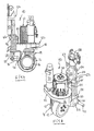
- the drive unit 10 is shown in more detail.
- the truck is a tricycle. It may be a common handlebar or drawbar steered truck also with a four-wheel or Jardinradfahrwerk.
- a drive wheel 12 is rotatably mounted about a horizontal axis in a turntable 14 about a horizontal axis.
- the turntable 14 has an angle gear 16 and an upper horizontal sprocket 18, on which a drive motor 20 is mounted.
- the drive motor 20 may be a three-phase motor or else a DC motor, which sets the drive wheel 12 in rotation via the gear 16.
- the ring gear 18 is rotatably mounted in a bearing member 22 about a vertical axis. On the upper side of the bearing member 22 sits upright a steering motor 24 which rotates the turntable 14 about the vertical axis when it is driven in accordance with a steering sensor.
- the described components are conventional and therefore need not be further discussed in detail.
- the bearing component 22 has an upper horizontal portion and an apron 26 extending differently far down therefrom, which is partly formed in a circular arc shape. However, it is partially open at the rear and forms below the disc 18 a horizontal paragraph 28 from. From this are stock approaches 30, 32 down. They are approximately parallel and at a distance from each other. As shown in Figs. shows, 32 relatively short arms are hinged to the bearing lugs 30, 32. At the bearing shoulder 30, a link 34 and the bearing lug 32, a link 36 is articulated. The link 36 is articulated on the outside of the bearing shoulder 32 and the handlebar 34 on the inside of the bearing shoulder 30. The articulation via pivot in corresponding holes of the bearing lugs 30, 32, which is not shown in detail. Only in Fig. 2 and 6, a bearing pin can be seen at 38.
- the links 34, 36 are welded to a tube 40. With the tube they form a unit. Through the pipe a bearing rod or shaft 42 is inserted, which is mounted on the frame 100 of the truck (Fig. 1).
- an upper bearing shoulder 44 is mounted on the back of the drive motor 20, which is arranged approximately in the middle between the lower bearing lugs 30, 32.
- a single upper link 46 is articulated, which is hinged at the other end to a lower projection 48 of a mounting portion 50.
- the links 34, 36 and 46, the bearing lugs 30, 32 and the attachment portion 50 thus form a parallelogram linkage, which allows an approximately vertical movement of the drive unit 10.
- the mounting portion 50 has on opposite sides of a one-piece molded jacket of a lift cylinder 52 in-plane mounting flanges 54, 56 with two mounting holes for attachment to a wall portion of the vehicle frame 100.
- a flange 58 is attached for the purpose of connection with the load part 102 of the truck.
- the bearing pin with the bearing lugs 30, 32 disengage. If the bearing rod 42 is pulled out of the tube 40, the drive unit is free and can be removed. This is possible naturally only if previously the attachment of the flanges 54, 56 has been solved on the frame.
- the lower arm 34, 36 are mounted on the frame 100 of the drive member on the same axis as the one arm of the lever 110 for the Hubgestfite. In this way, the construction cost is kept very low and the drive unit made compact.
Landscapes
- Engineering & Computer Science (AREA)
- Transportation (AREA)
- Structural Engineering (AREA)
- Combustion & Propulsion (AREA)
- Mechanical Engineering (AREA)
- Chemical & Material Sciences (AREA)
- Civil Engineering (AREA)
- Life Sciences & Earth Sciences (AREA)
- Geology (AREA)
- Vehicle Body Suspensions (AREA)
- Handcart (AREA)
- Forklifts And Lifting Vehicles (AREA)
- Arrangement Or Mounting Of Propulsion Units For Vehicles (AREA)
Applications Claiming Priority (1)
| Application Number | Priority Date | Filing Date | Title |
|---|---|---|---|
| DE102006041684A DE102006041684A1 (de) | 2006-09-06 | 2006-09-06 | Vormontageeinheit für den Antrieb eines Flurförderzeugs |
Publications (3)
| Publication Number | Publication Date |
|---|---|
| EP1897842A2 true EP1897842A2 (fr) | 2008-03-12 |
| EP1897842A3 EP1897842A3 (fr) | 2009-05-06 |
| EP1897842B1 EP1897842B1 (fr) | 2010-07-14 |
Family
ID=38683476
Family Applications (1)
| Application Number | Title | Priority Date | Filing Date |
|---|---|---|---|
| EP07015655A Active EP1897842B1 (fr) | 2006-09-06 | 2007-08-09 | Unité de prémontage pour l'engrenage d'un chariot de manutention |
Country Status (5)
| Country | Link |
|---|---|
| US (1) | US7854280B2 (fr) |
| EP (1) | EP1897842B1 (fr) |
| CN (1) | CN101138946B (fr) |
| DE (2) | DE102006041684A1 (fr) |
| ES (1) | ES2344809T3 (fr) |
Cited By (2)
| Publication number | Priority date | Publication date | Assignee | Title |
|---|---|---|---|---|
| EP2284118A3 (fr) * | 2009-08-14 | 2011-12-21 | Jungheinrich Aktiengesellschaft | Support d'entraînement pour le stockage rotatif d'une unité d'entraînement d'un chariot de manutention |
| EP3470297A1 (fr) * | 2017-10-10 | 2019-04-17 | UniCarriers Europe AB | Unité d'entraînement pour camion industriel et chariot industriel comportant une telle unité d'entraînement |
Families Citing this family (15)
| Publication number | Priority date | Publication date | Assignee | Title |
|---|---|---|---|---|
| US8752657B2 (en) * | 2011-04-19 | 2014-06-17 | Power Handling, Incorporated | Pallet jack power assembly |
| US9623891B2 (en) | 2011-04-19 | 2017-04-18 | Power Handling, Incorporated | Pallet jack power assembly |
| CN103640446B (zh) * | 2013-11-28 | 2016-08-17 | 苏州先锋物流装备科技有限公司 | 一种驱动安装减震系统 |
| CN104003330B (zh) * | 2014-05-29 | 2017-01-11 | 诺力机械股份有限公司 | 一种搬运车 |
| CN104401199A (zh) * | 2014-11-28 | 2015-03-11 | 浙江上加机械有限公司 | 一种用于电子助力转向驱动总成的避震支架 |
| CN104925695B (zh) * | 2015-06-25 | 2018-01-30 | 重庆川渝精工机械配件开发有限公司 | 一种减震托盘搬运车 |
| CN106672853B (zh) * | 2015-11-06 | 2019-02-19 | 湖南南车时代电动汽车股份有限公司 | 一种全承载式客车动力总成装配方法及工装 |
| CN105459746B (zh) * | 2015-11-09 | 2020-01-17 | 邱圣渊 | 车辆独立后悬架装置 |
| CN105417440A (zh) * | 2015-11-20 | 2016-03-23 | 安徽依诺玛智能科技有限公司 | 一种用于激光导向avg叉车的立式驱动机构 |
| CN105752886B (zh) * | 2016-02-05 | 2020-12-04 | 广东嘉腾机器人自动化有限公司 | 一种可自适应地面的叉车从动轮系 |
| CN106314032B (zh) * | 2016-09-30 | 2018-10-26 | 宁波介量机器人技术有限公司 | 一种直线换向随动轮 |
| CN108069366A (zh) * | 2016-11-15 | 2018-05-25 | 比亚迪股份有限公司 | 一种车辆及其转向结构 |
| CN108407547A (zh) * | 2018-04-26 | 2018-08-17 | 深圳市爱途仕智能科技有限公司 | 电动万向轮 |
| CN110834494B (zh) * | 2018-08-17 | 2023-01-20 | 深圳创维数字技术有限公司 | 一种万向轮及具有该万向轮的载体 |
| US10946884B2 (en) * | 2019-06-20 | 2021-03-16 | Larry Simpson | Pneumatic cylinder actuated pallet jack assembly |
Citations (4)
| Publication number | Priority date | Publication date | Assignee | Title |
|---|---|---|---|---|
| EP0209502A2 (fr) * | 1985-07-08 | 1987-01-21 | BT Industries Aktiebolag | Agencement de chariots élévateurs |
| EP0383254A2 (fr) * | 1989-02-17 | 1990-08-22 | Wagner Fördertechnik GmbH & Co KG | Chariot élévateur avec un élément de propulsion précontraint verticalement par ressorts |
| GB2293363A (en) * | 1994-09-26 | 1996-03-27 | Linde Ag | Lift Truck |
| US6488297B2 (en) * | 2000-01-14 | 2002-12-03 | Kabushiki Kaisha Toyoda Jidoshokki Seisakusho | Suspension device of industrial vehicle |
Family Cites Families (16)
| Publication number | Priority date | Publication date | Assignee | Title |
|---|---|---|---|---|
| US2359493A (en) * | 1941-07-03 | 1944-10-03 | Irvin F Schreck | Lift truck |
| US2417394A (en) * | 1942-12-17 | 1947-03-11 | Yale & Towne Mfg Co | Lift truck |
| US2370866A (en) * | 1943-07-05 | 1945-03-06 | Salsbury Corp | Industrial truck |
| US2598151A (en) * | 1949-09-29 | 1952-05-27 | Market Forge Co | Lift truck |
| US3249170A (en) * | 1963-11-07 | 1966-05-03 | Yale & Towne Inc | Motorized lift truck |
| US3515233A (en) * | 1968-05-08 | 1970-06-02 | Crown Controls Corp | Articulated industrial truck |
| DE3420146C2 (de) * | 1984-05-30 | 1986-11-27 | Carl Hurth Maschinen- und Zahnradfabrik GmbH & Co, 8000 München | Lenkkettenanschluß |
| IT208008Z2 (it) * | 1986-07-15 | 1988-03-31 | Pezzolato Off Constr Mecc Spa | Veicolo per la manipolazione a distanza di carichi |
| US4754837A (en) * | 1987-04-30 | 1988-07-05 | The Raymond Corporation | Lift truck steering apparatus |
| FR2626535B1 (fr) * | 1988-01-29 | 1991-08-16 | Mic Sa | Chariot de manutention |
| AU4023893A (en) * | 1993-04-01 | 1994-10-24 | Dalnevostochnaya Gosudarstvennaya Morskaya Akademia Imeni Admirala G.I. Nevelskogo | Loader |
| DE4342944C2 (de) * | 1993-12-16 | 1996-05-23 | Jungheinrich Ag | Flurförderzeug |
| US5820163A (en) * | 1996-07-08 | 1998-10-13 | Ford Global Technologies, Inc. | Tilting, telescoping and energy absorbing steering column |
| CN2485286Y (zh) * | 2001-05-30 | 2002-04-10 | 李文清 | 拖板车 |
| DE10221311B4 (de) * | 2002-05-14 | 2004-09-09 | Jungheinrich Ag | Niederhub-Flurförderzeug |
| US7267349B2 (en) * | 2004-09-03 | 2007-09-11 | Beech Engineering & Manufacturing | Material handling lift vehicle and suspension system for use therewith |
-
2006
- 2006-09-06 DE DE102006041684A patent/DE102006041684A1/de not_active Withdrawn
-
2007
- 2007-08-09 ES ES07015655T patent/ES2344809T3/es active Active
- 2007-08-09 EP EP07015655A patent/EP1897842B1/fr active Active
- 2007-08-09 DE DE502007004375T patent/DE502007004375D1/de active Active
- 2007-08-30 US US11/847,583 patent/US7854280B2/en active Active
- 2007-09-05 CN CN2007101497882A patent/CN101138946B/zh active Active
Patent Citations (4)
| Publication number | Priority date | Publication date | Assignee | Title |
|---|---|---|---|---|
| EP0209502A2 (fr) * | 1985-07-08 | 1987-01-21 | BT Industries Aktiebolag | Agencement de chariots élévateurs |
| EP0383254A2 (fr) * | 1989-02-17 | 1990-08-22 | Wagner Fördertechnik GmbH & Co KG | Chariot élévateur avec un élément de propulsion précontraint verticalement par ressorts |
| GB2293363A (en) * | 1994-09-26 | 1996-03-27 | Linde Ag | Lift Truck |
| US6488297B2 (en) * | 2000-01-14 | 2002-12-03 | Kabushiki Kaisha Toyoda Jidoshokki Seisakusho | Suspension device of industrial vehicle |
Cited By (2)
| Publication number | Priority date | Publication date | Assignee | Title |
|---|---|---|---|---|
| EP2284118A3 (fr) * | 2009-08-14 | 2011-12-21 | Jungheinrich Aktiengesellschaft | Support d'entraînement pour le stockage rotatif d'une unité d'entraînement d'un chariot de manutention |
| EP3470297A1 (fr) * | 2017-10-10 | 2019-04-17 | UniCarriers Europe AB | Unité d'entraînement pour camion industriel et chariot industriel comportant une telle unité d'entraînement |
Also Published As
| Publication number | Publication date |
|---|---|
| US7854280B2 (en) | 2010-12-21 |
| US20080053744A1 (en) | 2008-03-06 |
| CN101138946B (zh) | 2010-12-08 |
| CN101138946A (zh) | 2008-03-12 |
| ES2344809T3 (es) | 2010-09-07 |
| EP1897842A3 (fr) | 2009-05-06 |
| EP1897842B1 (fr) | 2010-07-14 |
| DE102006041684A1 (de) | 2008-03-27 |
| DE502007004375D1 (de) | 2010-08-26 |
Similar Documents
| Publication | Publication Date | Title |
|---|---|---|
| EP1897842B1 (fr) | Unité de prémontage pour l'engrenage d'un chariot de manutention | |
| EP1808402B1 (fr) | Chariot élévateur à petite levée | |
| DE60130725T2 (de) | Gabelstapler mit geringerem wenderadius und mit mitteln zur vereinfachung der wartungsarbeiten | |
| EP2956315B1 (fr) | Suspension de roue conçue pour un véhicule automobile | |
| EP0808747A1 (fr) | Système de hayon élévateur | |
| DE602004007935T2 (de) | Lenkvorrichtung für steuerräder | |
| DE19935008B4 (de) | Gabelniederhubwagen | |
| EP1932799B1 (fr) | Chariot de manutention | |
| EP0332037B1 (fr) | Dispositif de relevage d'essieu | |
| DE102007045912A1 (de) | Landwirtschaftliches Fahrzeug | |
| DE102007057678A1 (de) | Kippmechanismus für ein Hubgerüst eines Flurförderzeugs und Transportverfahren für ein Flurförderzeug | |
| EP2066538B1 (fr) | Portique de lavage et procédé de montage d'un portique de lavage | |
| EP0955230B1 (fr) | Véhicule utilitaire avec plate-forme de conduite basculante et mécanisme de basculement | |
| EP0557763B1 (fr) | Machine de fraisage | |
| EP1500525B1 (fr) | Essieu rigide pour un véhicule, notamment un essieu rétractable poussé ou trainé pour poids lourd ou autobus | |
| EP3771617B1 (fr) | Timon pour un chariot de manutention | |
| EP2489552B1 (fr) | Véhicule automobile avec un rétroviseur | |
| EP0391290B1 (fr) | Chariot élévateur à fourches | |
| DE102013112633B4 (de) | Deichselhubwagen | |
| EP3771616B1 (fr) | Chariot de manutention, en particulier chariot élévateur | |
| EP1298040B1 (fr) | Boîtier de moteur pour chariot industriel | |
| EP4110685B1 (fr) | Dispositif de levage d'une remorque de train de manutention et remorque de train de manutention comportant un dispositif de levage | |
| EP0940322A1 (fr) | Chassis pour véhicule utilitaire lourd | |
| DE10134282A1 (de) | Flurförderzeugflotte und Verfahren zum Herstellen der Flurförderzeugflotte | |
| EP1466857B1 (fr) | Chassis pour un chariot de manutention pour rayonnages hauts |
Legal Events
| Date | Code | Title | Description |
|---|---|---|---|
| PUAI | Public reference made under article 153(3) epc to a published international application that has entered the european phase |
Free format text: ORIGINAL CODE: 0009012 |
|
| AK | Designated contracting states |
Kind code of ref document: A2 Designated state(s): AT BE BG CH CY CZ DE DK EE ES FI FR GB GR HU IE IS IT LI LT LU LV MC MT NL PL PT RO SE SI SK TR |
|
| AX | Request for extension of the european patent |
Extension state: AL BA HR MK YU |
|
| PUAL | Search report despatched |
Free format text: ORIGINAL CODE: 0009013 |
|
| AK | Designated contracting states |
Kind code of ref document: A3 Designated state(s): AT BE BG CH CY CZ DE DK EE ES FI FR GB GR HU IE IS IT LI LT LU LV MC MT NL PL PT RO SE SI SK TR |
|
| AX | Request for extension of the european patent |
Extension state: AL BA HR MK RS |
|
| 17P | Request for examination filed |
Effective date: 20090610 |
|
| AKX | Designation fees paid |
Designated state(s): DE ES FR GB IT SE |
|
| GRAP | Despatch of communication of intention to grant a patent |
Free format text: ORIGINAL CODE: EPIDOSNIGR1 |
|
| GRAS | Grant fee paid |
Free format text: ORIGINAL CODE: EPIDOSNIGR3 |
|
| GRAA | (expected) grant |
Free format text: ORIGINAL CODE: 0009210 |
|
| AK | Designated contracting states |
Kind code of ref document: B1 Designated state(s): DE ES FR GB IT SE |
|
| REG | Reference to a national code |
Ref country code: GB Ref legal event code: FG4D Free format text: NOT ENGLISH |
|
| REF | Corresponds to: |
Ref document number: 502007004375 Country of ref document: DE Date of ref document: 20100826 Kind code of ref document: P |
|
| REG | Reference to a national code |
Ref country code: SE Ref legal event code: TRGR |
|
| REG | Reference to a national code |
Ref country code: ES Ref legal event code: FG2A Ref document number: 2344809 Country of ref document: ES Kind code of ref document: T3 |
|
| PLBE | No opposition filed within time limit |
Free format text: ORIGINAL CODE: 0009261 |
|
| STAA | Information on the status of an ep patent application or granted ep patent |
Free format text: STATUS: NO OPPOSITION FILED WITHIN TIME LIMIT |
|
| 26N | No opposition filed |
Effective date: 20110415 |
|
| REG | Reference to a national code |
Ref country code: DE Ref legal event code: R097 Ref document number: 502007004375 Country of ref document: DE Effective date: 20110415 |
|
| REG | Reference to a national code |
Ref country code: FR Ref legal event code: PLFP Year of fee payment: 10 |
|
| REG | Reference to a national code |
Ref country code: FR Ref legal event code: PLFP Year of fee payment: 11 |
|
| REG | Reference to a national code |
Ref country code: FR Ref legal event code: PLFP Year of fee payment: 12 |
|
| PGFP | Annual fee paid to national office [announced via postgrant information from national office to epo] |
Ref country code: IT Payment date: 20230831 Year of fee payment: 17 Ref country code: GB Payment date: 20230824 Year of fee payment: 17 Ref country code: ES Payment date: 20230918 Year of fee payment: 17 |
|
| PGFP | Annual fee paid to national office [announced via postgrant information from national office to epo] |
Ref country code: SE Payment date: 20230823 Year of fee payment: 17 Ref country code: FR Payment date: 20230821 Year of fee payment: 17 Ref country code: DE Payment date: 20230822 Year of fee payment: 17 |